Table of Contents
Advertisement
Advertisement
Table of Contents

Related Manuals for FlexiForce Force70XQ


Summary of Contents for FlexiForce Force70XQ
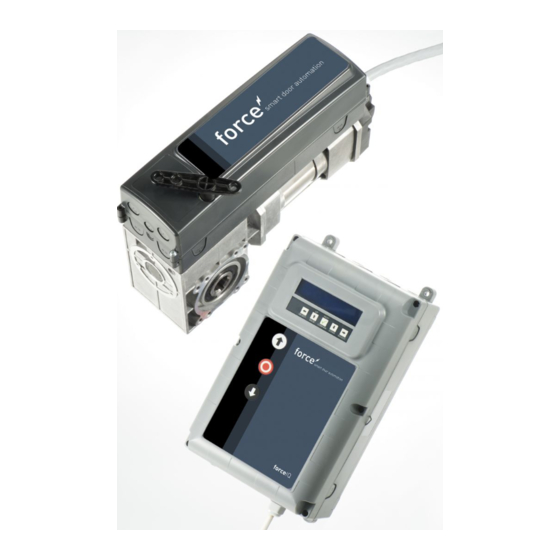
- Page 1 forceIQ manual manual version 3.0 software version 1.147.c-1 DEF5000...
-
Page 2: Copyright And Disclaimer Notice
– forceIQ Copyright and Disclaimer Notice Although the contents of this publication have been compiled with the greatest possible care, FlexiForce cannot accept liability for any damage that might arise from errors or omissions in this publication. We also reserve the right to make appropriate technical modifications/replacements without prior notice. No rights can be derived from the contents of this document. Colour guides: Colour differences may occur due to different printing and publication methods. Copyright FlexiForce Group 2015. All rights reserved 2 www.flexiforce.com... -
Page 3: Table Of Contents
manual – forceIQ Contents Copyright and Disclaimer Notice 2 Contents 3 1. About this Manual 1.1 Safety Symbols Used in this Manual 4 2. force70/100/140 operator ... -
Page 4: About This Manual
manual – forceIQ About this Manual _____________________________________________________________ All users and owners of the Industrial door must read, understand and obey the information and instructions in this manual. Failure to do so may result in damage to, or failure of the equipment, and possible injury to persons. This manual contains functional descriptions and installation information for an Industrial door. When information or instructions are applicable to all the methods of operation or models, there are no operator types or modelnumbers in the title. When information or instructions are applicable to specific methods of operation or models, the applicable operation type or model numbers appear in the title. 1.1. Safety Symbols Used in this Manual The following safety symbols are used in this manual: Indicates a general warning Indicates an electrical hazard Specific useful information concerning the installation. 4 www.flexiforce.com... -
Page 5: Force70/100/140 Operator
– forceIQ 2. Force70XQ/100XQ/100XC/140XQ operator 2.1. Safety instructions Follow all instructions since incorrect installation can lead to severe injury. • Check that the temperature range marked on the operator is suitable for the location. • Check that the door is moving smooth and correct before assembling the operator. • Check that the door is in good mechanical condition and is correctly balanced. • After installation, ensure that the mechanism is properly adjusted and that the protection system • and any manual release function correctly. Ensure that entrapment between the driven part and the surrounding fixed parts due to the • opening movement of the driven part is avoided. External push button units are to be located within direct sight of the door but away from • moving parts. Unless it is key operated, it is to be installed at a minimum height of 1,5 m and not accessible to the public. 2.2. Preparation Before you start make sure that the following preparations are done: Approval/communication with customer completed. • Materials on site are complete. • All measurements are correct. • 2.3. Electrical preparations ... -
Page 6: Assembling The Drive Unit
manual – forceIQ 2.4. Assembling the drive unit The door must be correctly installed, balanced and be in closed position before the assembly of the operator. For the operator a mounting attachment of >500N is required. 1. Attach the first stop ring to the shaft. 2. Attach the wall bracket with 4 screws and washers to the motor. 3. Push the operator completely against the stop ring. 4. Mount the wall bracket to the wall with two suitable screws and washers. Per mounting attachment >500N is required. 5. Disengage the drive unit from the door shaft by moving the handle clockwise until it stops, then aim for the keyways at the door shaft and the operator. *The wedge should protrude a few mm from the wall bracket. 6. Attach the second stop ring. A gap of a few mm should remain between the stop ring and the wall bracket. 7. Tighten all screws. 8. Route the cable down to the control unit. 6 www.flexiforce.com... -
Page 7: Drawings / Dimensions
manual – forceIQ 2.5 Drawings / dimensions _____________________________________________________________________________________ Force100XQ/140XQ Force100XC 7 www.flexiforce.com... -
Page 8: Forceiq Control Unit
manual – forceIQ 3. forceIQ control unit 3.1 Installation 1 1. At the rear of the control unit you have to assemble 4 enclosure brackets before mounting it to the wall. Use the four small 5x12 screws. 2. Mount the Control unit approx. 1.7m above the floor (measured from the upper side of the box). 3. Connect the cables from the door leaf and the drive unit, according in the instructions by the wiring diagram. The control unit is now assembled and ready to be functionally installed. See paragraph "Programming" concerning the programming procedure. ... -
Page 9: Forceiq 230V Single Phase Preparation
manual – forceIQ 3.1.1 ForceIQ 230V single phase preparation Connect as below when you use the ForceIQ with a 230V single phase motor. Make sure Fuse F4 is 100mA medium and that KL13‐1 and KL13‐2 are connected together. Medium ____________________________________________________________________________________________________ 3.1.2 ForceIQ 400V preparation Connect as below when you use the ForceIQ with a 400V motor. Make sure Fuse F4 is 80mA slow and that KL13‐2 and KL13‐3 are connected together. Slow ... -
Page 10: Technical Data
manual – forceIQ 3.2 Technical data Dimensions (approx.): 345x215x135mm Main supply voltage L1, L2, L3, N, PE: forceIQ‐ 400V, 50HZ / forceIQ‐230 230V, 50Hz. Fuse protection 10A K ‐ characteristic Voltage 24V DC, max. 320mA Access input 24V DC, All inputs must be absolutely potential free connected. Minimum duration of input signal control command >100ms. Safety circuit / Emergency stop Connect all inputs absolutely potential free; at interruption in the security circuit, it is not longer possible of electrical operation of the motor, even in hold‐to‐run mode. Input safety rail F or electrical safety strips with 8.2kΩ, load resistor and for dynamic optical systems. Relay output ... -
Page 11: Forceiq Menu Overview
manual – forceIQ forceIQ menu overview 3.3. ForceIQ ______________________________________________________________ 1. Display 2. Keypad 3. Push‐button "UP" (door opens) 4. Push‐button "STOP" (door stays in position) 5. Push button "DOWN" (door closes) Menu selection (left) Menu selection (right) Confirm Change number values & end position setting ‐1 push, return to the menu selection ‐2 push, return to the operating mode Change number values & end position setting. 11 www.flexiforce.com... -
Page 12: Access The Menu
manual – forceIQ 3.3.1. Access the Menu 1. Press and hold the push‐button STOP for 6 seconds to activate the keypad and to access the menu. 2. Enter the access code*. You now have access to the menu. The display will show plain text commands, messages, and error messages. The keypad is used to navigate through the menu, to confirm and to save.* Standard access code is "00000". 3.4. Programming Before programming the Control Unit: Make sure that you connect al the devices like in the Basic Wiring Diagram. • Place the door 1.5m above the floor. • Ensure that the floor is clean and free from cables etc. • Programming can only be carried out using the set of buttons in the control box, not an external push button box or radio control. For doors with small drums and without safety features, there may be a risk of the cable unwinding. Check therefore that the cable is placed correctly on the drum. In the main menu it is possible to switch between the following menu items by pressing the or button. 1) Language 13 ... -
Page 13: Changing The Language
manual – forceIQ 3.4.1. Changing the language • use the or buttons to select your desired language. Dutch German English Italian French Spanish Polish Swedish Hungarian Romanian • Press to confirm and save. • Press to return to the main menu. • Press once more to enter the maneuvering mode. 13 ... -
Page 14: Motor Setup
manual – forceIQ 3.4.2 Motor setup Use the or buttons to select one of the following menu items: 1) Motor direction 2) Encoder direction 3) Motor controller 4) Limit sw. type 5) Lift force detection 6) Inv. profile up (Only for inverter operator) 7) Inv. profile down (Only for inverter operator) 8) Fu profile boost (Only for inverter operator) 1) Motor direction: Use the or button to change the motor direction to "left" or "right". Press twice to confirm. 2) Encoder direction: Use the or buttons to change the encoder direction to "Clockwise" or "Anti‐ clockwise. Press twice to confirm. 3) Motor controller: Use the or buttons to choose between "Contactor relay" and "Inverter rue" " "... - Page 15 manual – forceIQ 6) Inv. profile up Only for inverter operator Use the buttons to adjust the following parameters: • Max speed (Hz) the maximum speed after acceleration • Min speed (Hz) the speed after deceleration • Start ramp (ms) acceleration time • Slowdown slope (ms) deceleration time • Stop ramp (Incr.) value before the end position were the slope has to start Press to return to the main menu. Press once more to return to the manoeuvring mode 7) Inv. profile down Only for inverter operator Use the buttons to adjust the following parameters: Max speed (Hz) the maximum speed after acceleration ...
-
Page 16: Adjusting The End Position
manual – forceIQ 3.4.3. Adjusting the end position Warning: Risk of material damage: The door could be moved beyond the upper and lower end position manually during installation ( in hold to run mode). This may result in damage to the door. Observe the door during setting the end positions permanently. Before adjusting the end position: Place the door in the middle position. Check if the door goes up when the button is pushed. If the door does not go up then change the direction of the motor. (See page 12 "Motor direction") Use the or buttons to select one of the following menu items: 1) Top 2) Bottom 3) Brake offset 4) Fine pitch up 5) Fine pitch down 6) Pre end position 7) Safety limit 8) Pos med speed Press to enter the selected menu item. 1) Top: Run the door in the desired position using or press to confirm end position. . Check if the counter counts up when the door goes up. If the counter doesn't count up, change the direction of the encoder. (See paragraph "Motor setup"). Use the and ... - Page 17 manual – forceIQ 6) Pre end position: Use the buttons to adjust this position. This is the point where the safety edge changes from reverse to stop when triggered. 7) Safety limit: Use the buttons to adjust this position. here you can adjust the safety limit switch. So when the door is running through the end position, the safety limit switch will automaticly stop the operator. Default is 100 : Use the 8) Position medium speed buttons to adjust this position. Only for inverter operator) The position medium speed is the position at which the door will switch from fast speed to medium speed when the door is moving down. Please let the door run four times up and down. If the end positions are correct, Press to return to the main menu . Press once more to return to the maneuvering mode. After adjusting the end positions, check the quick release or the safety chain if they work probably. Check this when the door is in close position. When it is hard to move the chain or quick release, then check if there is tension on the cables and springs and if the door is not pushing too tight on the floor. Brake offset The brake offset parameter is used for automatic mode with encoder. It is the initial value where the automatic brake point adjustment function switching on the brake and switching of the motor. This function detects when the door does not stop on the defined endpoint and modifies the brake offset point. For a ...
-
Page 18: Safety Device
manual – forceIQ 3.4.4. Safety Device Depending of what kind of safety device is used, you can choose between following actions when safety device is triggered. Down full reverse : door returns to top end position, by activation while door is closing. • Down part reverse: door returns a couple of cm, by activation while door is closing. • Down stop: door stops, by activation while door closing. • Pull‐in protect: door stops by activation while door go's up. • Down full /sw off: to adjust the position to deactivated the photocell that is active in downward • direction. Use the buttons to adjust the position to deactivated the photocell. Pull‐in masked: to adjust the position to deactivated the photocell that is active in upward direction • Use the buttons to adjust the position to deactivated the photocell. Use the or buttons to select one of the following menu items: 1 ) 4‐wire photocell KL5 2) 2‐wire photo KL6 3) OSE 1 setup KL3 4) OSE 2 setup KL4 5) Safety 1 KL2 1‐2 6) Safety 2 KL2 3‐4 7) Reverse Delay 8) Fine pitch disable photoc. ... - Page 19 manual – forceIQ 4) OSE 2 setup KL4: Use the or buttons to select one of the following menu items: • Disabled: When KL4 is not in use • OSE: When safety device that works with OSE signal is connected e.g. opto sensors • Wireless OSE: When a wireless OSE safety device is connected • 4‐w photoc.: When 4 wired photocell is connected e.g. pre‐running photocel 5) Safety 1 KL2 1‐2: Use the or buttons to select one of the following menu items: • Disabled: When KL2 1‐2 is not in use • 8k2: when a safety edge is connected that deactivated 8.2 kΩ Airwave switch: when airwave switch with 8.2 kΩ is connected. The control unit need a test signal ...
-
Page 20: Operating Mode
manual – forceIQ 3.4.5. Operating mode Use the buttons to select one of the following menu items: Automatic UP/DOWN: the door opens and closes in automatic mode. (only if safety edges are ok and activated) • • Deadman UP/Down: the door opens and closes in hold to run mode • Automatic UP/Deadman DOWN: the door opens automatically and closes in hold to run mode If Automatic UP/DOWN is not in the menu, then there is something wrong with the safety devices or the connected safety devices is not activated in the menu. Photocells are not safe enough according safety standard, so you won't find automatic UP/DOWN in the menu. Connect one more safety edge for automatic UP/DOWN. Press to confirm and save the desired operating mode. Press to return to the main menu. Press once more to return to the manoeuvring mode 3.4.6. Code entry Use the / / ... -
Page 21: Special Setup
manual – forceIQ 3.4.7. Special setup Use the buttons to select one of the following menu items: 1) Auto close 2) Auto open 3) Partial open 4) Relays 5) Traffic light 6) CDM6 7) Door control mode 8) External buttons Auto close: 1) This will automatically close the door after the set delay. Use the buttons to select one of the following menu items: To set auto close : • Enabled • Close delay (use to set time, unlimited means the timer is on but isn't counting) • Trig. Auto close disabled • Max emergn rev. (use to set max. number of reverse after safety edge is triggered, after that number "auto close" stops) ... - Page 22 manual – forceIQ 2) auto open: This will open the door automaticly after the same delay as "auto close" Warning: "Auto open" is a test function. Only use for testing! 3: Partial open: If you push 2x the up botton the door will stop at this point or to adjust to the desired position. • Press twice to confirm and save the desired position. • Press to return to the main menu. • Press once more to return to the maneuvering mode. • 2x = reduced opening. Push 1 x by reduced opening and the door will fully open (Not possible with remote control button) 4 Relays: Use the ...
- Page 23 manual – forceIQ ** Ready for work: Trigger Number code Optical safety edge 1 (OSE 1 / KL3) 1 Optical safety edge 2(OSE 2 / KL4) or pre‐running photocell 2 Safety edge 1 (KL2 1/2 ) 4 Safety edge 2 (KL2 3/4) 8 4‐wire photocell (KL5) 16 2‐wire photocell (KL6) 32 Emergency stop (KL7) 64 Safety chain motor (KL8) 128 Passdoor (KL2) 256 Sum of all trigger 511 Example: if you want to switch the relay when OSE 1 is triggered, fill in 1 by ready to work. If you want to switch the relay when OSE 1 (1) or KL5 (16) is triggered fill in 17. (1 + 16) 5) Traffic light: This function is used when the door opening is not wide enough for two vehicles to pass at the same time and the traffic must be regulated: who may pass through the door first. Three relays are intended for the red and green lights, on the inside and the outside of the door. The 4th relay can be used for special applications, e.g. garage light, exhaust ventilation, stair light impulse. Traffic light setting can be set only in combination with optional traffic light module ...
-
Page 24: Service
manual – forceIQ If the door reverses due to a safety edge (OSE, photocell etc.) activation, the red light will be set on both sides at the fully open position. If the stop button is pressed, the two way traffic mode is aborted until the door is closed. The light state can be permanent green/red or red/red in open position depending on when the stop button is pressed. Between the end positions, the light will continue to flash if the stop button is pressed. The table shows which side that will have the green light depending on what was triggering the opening. The opposite side has red light. Opening command Inside green light Outside green light Contact unit button External up button (KL20‐1) External one button (KL20‐7) Radio up button (KL1‐4) Radio one button (KL1‐3) Induction loop 1 ... - Page 25 manual – forceIQ 1) Cycles: To view the number of door cycles 2) Software version: To view the current software version, 3) CFG XML export: To export the config XML, ( for internal use only) 4) Set time: Use / and / buttons to change the current date and time. 5) Maintenance complete: Select when maintenance is complete. The service intervals are now restored to its pre‐settings. 6) Maintenance intervals: To adjust the number of door cycles or the number or days to indicate when service is needed navigate to the "Maintenance intervals" menu item. Limit door cycles: To adjust the number of door cycles (between 11 and 999.999 cycles. Use the • button to adjust the number of door cycles. The default setting is 25.000 cycles. Limit days: To adjust the number of days (between 11 and 999.999 days). Use the button to adjust • the number of days. The default setting is 365 days. The display will show "Maintenance interval reached" when the number of days or cycles is reached. 7) Reset errors: To reset the errors shown. 8) Event history: To view the event history, use the / button to navigate through the history. 9) Clear event history: To clear the event history 10) CFG soft reset: for internal use only 11) Factory reset: To reset the control unit back to the factory settings. ...
-
Page 26: Optional Plug On
manual – forceIQ 4. Optional plug‐on modules The forceIQ control unit can also be programmed to handle multiple optional functions. When external equipments are needed to connect to the control unit, please read the enclosed documentation. The ForceIQ enables various plug on modules to be directly installed. These will be pushed in the designated plug‐in position and connected with the enclosed adapter cable to the mainboard of the forceIQ. Module Bracket Module Bracket is installed directly above the main board in the control housing. 2 3 4 1 ... -
Page 27: Forceld: Loop Detector
manual – forceIQ 4.2. forceLD: loop detector This is a double detector to connect 2 loops. The connection is at terminal KL23 in the ForceIQ. The detailed adjustments are described in the supplied manual and the wiring is shown in the electrical drawing. No need to adjust settings in the menu of the ForceIQ. Terminal Function 1 / 2 Loop 1 3 / 4 Loop 2 Terminal Function 1 / 2 Switching output 1 3 / 4 Switching output 2 5 + 24V DC 6 GND Setting DIP‐switches: DIP=switch Function 1 Frequency adjustment 2 Frequency adjustment 3 Sensitivity loop 1 4 Sensitivity loop 1 5 Sensitivity loop 2 6 ... -
Page 28: Forcerx4: Radio Receiver
manual – forceIQ 4.3. ForceRX4: radio receiver ForceTX4: Hand‐held transmitter This is a 4 channel radio receiver. The connecting is at terminal KL1 in the ForceIQ. The detailed adjustments are Described in the supplied manual and the wiring is shown in the electrical drawing. No need to adjust settings in the menu of the ForceIQ. The compatible transmitters are the ForceTX4 Channel 1 Impulse (open.stop/close) Channel 2 Open Channel 3 Close Channel 4 Stop 4.4. forceTL: traffic light The Traffic light module has 4 integrated relays. The connection is at terminal KL22 in the ForceIQ. The detailed adjustments are described in the supplied manual and the wiring is shown in the electrical drawing. For more info and adjustments see 3.4.7 traffic lights page 20. ... -
Page 29: Force Photocells
manual – forceIQ 4.5. Photocells (for example we use the OS‐IR) With the forceIQ two kits are possible Connect the photocells as below OS‐IR ForceIQ KL4 ForceIQ KL5 Brown 4 1 (transmitter) Brown 3 1 (receiver) Blue ( 1 4 both) yellow 2 3 black 1 1 See also basic wiring diagram Photocell 1, terminal KL5: Use the or arrow to navigate to the "Safety devices" menu. Press to enter the menu. •... -
Page 30: Forceoce
manual – forceIQ 4.6: forceOSE Connect: Connect the 3pole connector of the forceOSE Optosensor kit to KL3 in the control unit. If you use a slack rope switch, you can connect the 2pole connector to KL7. If you use a pass door switch, you can connect the 2pole connector to KL2 1‐2 or KL2 3‐4. Make sure a 8.2 kΩ is connected if you use KL2 (See also basic wiring diagram) Settings optosensor Use the or buttons to navigate to the "Safety device" menu. • Press to enter the menu. • Use the or buttons to select "OSE1 KL3". Press to confirm. • Use the or buttons to select "OSE". Press to confirm. • Use the or buttons to select "down full rev.". Press to confirm • Press to return to the main menu. • Press once more to enter the manoeuvring mode. • ... - Page 31 manual – forceIQ Settings for the PSE: Use the or buttons to navigate to the "Safety device" menu. • Press to enter the menu. • Use the or buttons to select "Safety1". Press to confirm. • Use the or buttons to select "Airwave switch". Press to confirm. • Use the or buttons to select "down full rev.". • Press to confirm and save. • Press to return to the main menu. • Press once more to enter the maneuvering mode. • settings for the pass door switch: Use the or buttons to navigate to the "Safety device" menu. •...
-
Page 32: Force668Lm Electronic Lock
manual – forceIQ 4.8 force668LM, electronic lock. For this lock you need an additional power supply. If the lock works the wrong way round, then swap KL14 and KL15 Connecting LM668 to Force IQ control box Use the or buttons to navigate to the "Special setup" menu. Press to enter the menu. • Use the or buttons to select "Relays". Press to confirm. •... -
Page 33: Trouble Shooting
manual – forceIQ Trouble shooting 5.1 Event message Event message Reason OSE 1 ERROR Safety device on OSE 1 port is defect KL3 OSE 2 ERROR Safety device on OSE 2 port is defect KL4 SAFE.EDGE 1 ERR. Safety device on SR1 port is defect KL2:1‐2 SAFE.EDGE 2 ERR. Safety device on SR2 port is defect KL2:3‐4 4W‐PHOTOC. ERROR Safety device on 4wire port is defect DOOR SAFETY Safety chain triggered, open circuit KL 7 MOTOR SAFETY Safety chain triggered, open circuit KL 8 BLOCKED POSITIONER Encoder communication error or no encoder KL18 INVERTER ERROR Inverter communications error BATTERY EMPTY Dalmatic encoder reports its batteries are empty OUT OF RANGE Door moved past the end positions UNAUTHORIS. MOVE Door moved when it was not supposed to DOOR TOO SLOW Door did not move even though it should have DOOR TOO FAST Door was moving too fast (door speed monitoring) WRONG DIRECTION Door was moving in the wrong direction ERROR BAD CONFIG The stored configuration was missing/invalid ... -
Page 35: Appendix
manual – forceIQ Appendix 6. 1 Additional function‐terminals 34 www.flexiforce.com... - Page 36 manual – forceIQ Terminal group A: Terminal group B: 35 www.flexiforce.com...
- Page 37 manual – forceIQ Terminal group C: Terminal group D: www.flexiforce.com...
- Page 38 manual – forceIQ BA1-kit BA3-kit Motor unit BA2-kit limit sw. Push B BA4-kit Loop det. Traffic light (not in use) Alternating up-stop-down impulse NOTE! Terminals KL17 – 23 are numbered from right to left! NOTE! Safety device Load up to 230V, 4A Safety device BA5-kit Ph.1: Car wash,...
- Page 39 manual – forceIQ Motor 400V Motor unit limit sw. Push B Encoder Green Yellow Spring Break Device sw. Thermo sw. in motor (not in use) Cluch release / chain sw. 17 – 23 are m right to left! o 230V, 4A OR CONTROL SBD-switch SBD-switch...
- Page 40 manual – forceIQ Steuerung MCU Steuerung MCU Steuerung MCU Steuerung MCU Traffi Warnlichter Rot Traffi Warning Lights Warnlichter Rot RED (BA1) Grün Warning Lights Innen Außen RED (BA1) Grün Innen Außen Innen Innen Außen Außen Lichtschranke(BA5) Photocells (BA5) Lichtschranke(BA5) Fernbedienung RX (BA4) Photocells (BA5) Steuerung MCU / Steuerung MCU /...
- Page 41 manual – forceIQ Steuerung MCU Steuerung MCU Steuerung MCU Steuerung MCU Steuerung MCU Steuerung MCU Offen - Außen Offen - Innen AMPEL Traffic Lights (BA3) Grün Innen Außen Offen - Außen Offen - Innen Schleifenerkennung (BA2) AMPEL Loop Detector (BA2) Traffic Lights (BA3) PCA Schleifenerkennung Steuerung MCU...
- Page 42 – forceIQ Declaration of Incorporation We: Flexi‐Force Group BV Hanzeweg 25 3771 NG Barneveld The Netherlands declare under our sole responsibility that the type of equipment : Industrial sectional overhead door drives force70XQ, force100XC, force100XQ, force140XQ and control units forceIQ and forceIQ‐230 with radio remote control, are in compliance with the following directives: 2004/108/EC Electro Magnetic Compatibility Directive (EMCD) 2002/95/EC Restriction of the use of Hazardous Substances in electrical and electronic equipment (RoHS) 1999/5/EC Radio and Telecommunications Terminal Equipment Directive (R&TTE) 2006/42/EC Machinery Directive (MD) the following essential health and safety requirements: 1.1.2, 1.1.3, 1.2.1, 1.2.2, 1.2.3, 1.2.4, 1.2.5, 1.2.6, 1.3.1, 1.3.2, 1.3.4, 1.3.7, 1.3.8, 1.3.9, 1.4.2, 1.5.1, 1.5.2, 1.5.4, 1.5.5, 1.5.6, 1.5.7, 1.5.10, 1.5.11, 1.5.12, 1.5.13, 1.5.16, 1.6.3, 1.6.4, 1.7.3, 1.7.4. Technical documentation for safe integration is provided Harmonized European standards which have been applied: EN 13849‐1 EN 61000‐6‐1 EN 61000‐6‐2 EN 61000‐6‐3 EN 61000‐6‐4 EN 12453 EN 60335‐1 ...
Need help?
Do you have a question about the Force70XQ and is the answer not in the manual?
Questions and answers