
Subscribe to Our Youtube Channel
Related Manuals for Berker RolloTec 2975


Summary of Contents for Berker RolloTec 2975
- Page 1 Bedienungsanleitung Operating Instructions Bedieningshandleiding Mode d’emploi RolloTec ® RolloTec ® Einsatz RolloTec ® Insert Inzetregelmoduul Insert Best.Nr. 2975 825 166 01 01.2003...
-
Page 2: Table Of Contents
Inhaltsverzeichnis 1. Funktion ......................4 RolloTec ® Einsatz mit RolloTec ® Taste ............5 RolloTec ® Einsatz mit RolloTec ® Funk-Taste ..........6 RolloTec ® Einsatz mit RolloTec ® Speicher-Taste ........... 7 RolloTec ® Einsatz mit RolloTec ® Aufsatzmodul Schaltuhr ......7 2. -
Page 3: Funktion
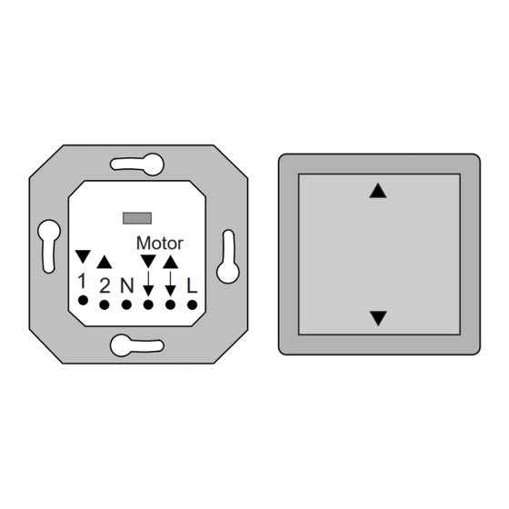
1. Funktion Der RolloTec ® Einsatz verfügt über 6 Anschlussklemmen und einen Steckverbinder Prog Zufall Astro zur Kontaktierung des Aufsatzes. Zusätzlich kann im Einsatz eine Der RolloTec ® Einsatz ist eine Komponente des RolloTec ® Systemes und wird in Schnittstelle Aufsatz Sensoranschluss 3-polige Klemme (liegt dem Aufsatz mit Sensoranschluss bei) positioniert werden. -
Page 4: Rollotec Einsatz Mit Rollotec Funk-Taste
RolloTec ® Einsatz mit RolloTec ® Funk-Taste RolloTec ® Einsatz mit RolloTec ® Speicher-Taste In dieser Kombination wird der RolloTec ® Einsatz als automatische Steuerung In dieser Kombination wird der RolloTec ® Einsatz als funkfernbedienbarer Taster mit zwei gespeicherten Jalousiefahrzeiten betrieben. betrieben. -
Page 5: Gefahrenhinweise
2. Gefahrenhinweise 3. Installationshinweise Achtung! Einbau und Montage elektrischer Geräte dürfen nur durch eine Wichtig: Die Sensorleitung führt Schutzkleinspannung (SELV). Installations- Elektrofachkraft erfolgen. vorschriften nach VDE 0100 beachten. Werden unterschiedliche Phasen verwendet, muss im Fehlerfall oder bei Anschluss Sensor: Arbeiten an der Installation allpolig abgeschaltet werden. UP-Verlegung (Bild A): Steuerleitungen nicht parallel zu Motorleitungen legen (Einkopplungsgefahr). - Page 6 AP-Verlegung (Schaltuhr mit Sensoranschluss) (Bild C): Der RolloTec ® Einsatz kann nur in Verbindung mit einem der folgenden Aufsätzen in Der Anschluss des Sensors bzw. des Adapters erfolgt über einen Stecker am Aufsatz. Betrieb genommen werden: ® RolloTec Taste Anschluss an Klemmblock im Einsatz: ®...
-
Page 7: Anschluss
4. Anschluss Anschluss RolloTec ® Einsatz mit Funk-fernbedienbarer Nebenstelle. Hinweis: Solange ein Auf-Befehl am Nebenstelleneingang ‘2’ anliegt, kann die Empfehlung: Zur Verschaltung zweier Einsätze, zwischen den Einsätzen Leitung Jalousie am Gerät selbst nicht manuell oder automatisch bedient werden. 5x1,5 mm² verwenden (1, 2, L, N, PE). ®... -
Page 8: Einsatz Mit 'Zentralsteuerung' Auf 2 Phasen
Anschluss RolloTec ® Einsatz mit ‘Zentralsteuerung’. Anschluss RolloTec ® Einsatz mit ‘Zentralsteuerung’ auf 2 Phasen. Beispiel B für 2 Jalousiemotoren: Der Anschluss auf mehreren Phasen bietet die Möglichkeit, die Zentralsteuerung auf einer anderen Etage oder in einem anderen Raum zu installieren. Einsatz mit Schaltuhr. - Page 9 Anschluss RolloTec ® mit Windalarm Anschluss RolloTec ® mit Windalarm (Zentralsteuerung mit 2 Gruppen) Bei Windalarm wird die Jalousie aufgefahren und bleibt dort verriegelt, bis der Wind Bei Windalarm wird die Jalousie aufgefahren und bleibt dort verriegelt, bis der Wind abnimmt.
-
Page 10: Rollotec
Anschluss RolloTec ® in Installationen mit separaten Fehlerstrom- 5. Technische Daten Schutzschaltern (FI) Nennspannung : AC 230 V, 50 Hz, N-Leiter erforderlich Um unerwünschtes Auslösen der FI-Schalter zu vermeiden, müssen die beiden Schaltleistung : max. 1 Motor 1000 W ‘Stromkreise’ galvanisch entkoppelt werden. Relaisausgang : 2 potentialbehaftete Schliesser Bitte Trennrelais verwenden. - Page 11 ........24 ® ® RolloTec insert with RolloTec clock timer attachment ........25 Berker GmbH & Co. KG 2. Warning ......................26 Abt. Service Center Klagebach 38 3. Installation Instructions ..................27 D-58579 Schalksmühle 4. Connection ......................30...
-
Page 12: Function
1. Function The RolloTec ® insert has six connection terminals and one connector for Prog Zufall Astro contacting the attachment. The RolloTec ® insert is a component of the RolloTec ® system and is installed in a Attachment interface Sensor connection In addition, a three-pole terminal (added to the attachment with sensor connection) Uhrzeit Datum... -
Page 13: Rollotec Insert With Rollotec Radio Push-Button
RolloTec ® insert with RolloTec ® radio push-button RolloTec ® insert with RolloTec ® clock timer attachment In this combination, the RolloTec ® insert is used as a radio-controlled push-button. In this combination, the RolloTec ® insert can be operated as an automatic control Zufall Astro Prog The radio push-button must be taught in to the desired transmitter channel... -
Page 14: Warning
2. Warning 3. Installation Instructions Attention: Electrical equipment must be installed and fitted by qualified Important: The sensor wiring carries protective low voltage (SELV). Please electricians only. observe the installation procedures as specified by VDE 0100. If different phases are used all poles will have to be disconnected in case of Connecting the Sensor: malfunctioning or when work is done on the installation. - Page 15 Surface installation (RolloTec ® timer with sensor evaluation) (Illustration C): The RolloTec ® insert can only be set into operation in conjunction with one of the following attachments: The sensor or adapter must be connected to the attachment by a plug. RolloTec ®...
-
Page 16: Connection
4. Connection Connection of RolloTec ® insert with IR remote control extension. Recommendation: To interconnect two inserts use 5x1.5 mm² wiring (1, 2, L, N, PE) Important: As long as an UP command is applied to extension input ‘2’ the louver between the inserts. -
Page 17: Insert With 2-Phase 'Central Control
Connection of RolloTec ® Insert with ‘central control’. Connection of RolloTec ® Insert with 2-phases ‘central control’. Example B for 2 louver motors: The connection to two phases facilitates the installation of the central control system within a different storey or room. Inserts with RolloTec ®... - Page 18 Connection of RolloTec ® with wind alarm. Connection of RolloTec ® with wind alarm (central control with two groups) In case of wind alarm, the louver is moved up and remains there in a locked condition In case of wind alarm, the louver is moved up and remains there in a locked condition until the wind ceases.
-
Page 19: Rollotec
Connection of RolloTec ® in installations using separate fault-current circuit 5. Specifications breakers (FI). Rated voltage : 230 V AC, 50 Hz, neutral conductor required To avoid undesired tripping of the FI circuit breakers the two ‘circuits’ must not be Switching capacity : one 1000 W motor max. -
Page 20: Klagebach
® RolloTec inzetmoduul met programmeertoets ..........42 ® RolloTec inzetmoduul met opzetmoduul schakelklok ........43 Berker GmbH & Co. KG 2. Veiligheidsinstructies ................... 44 Klagebach 38 D-58579 Schalksmühle 3. Installatie-instructies ................... 45 Germany 4. Aansluiting ......................48... -
Page 21: Functie
1. Functie Het RolloTec ® inzetmoduul heeft 6 aansluitklemmen en een stekerconnector voor Prog Zufall Astro contactering van het opzetmoduul. Aansluiting ® Het RolloTec inzetmoduul is een component van het jaloeziemanager systeem Sensor aansluiting voor opzetstuk Tevens kan in het inzetmoduul een 3-polige klem (bij verpakking opzetmoduul met Uhrzeit Datum en wordt in combinatie met... -
Page 22: Rollotec
RolloTec ® inzetmoduul met RolloTec ® zendtoets RolloTec ® inzetmoduul met RolloTec ® opzetmoduul schakelklok In deze combinatie wordt het RolloTec ® inzetmoduul als draadloze besturing In deze combinatie wordt het RolloTec ® inzetmoduul als automatische besturing met toegepast. De adapter met receiver dient op het gewenste zenderkanaal te worden programmeerbare schakeltijden gebruikt (zie bedieningshandleiding ‘RolloTec ®... -
Page 23: Veiligheidsinstructies
2. Veiligheidsinstructies 3. Installatie-instructies Attentie! Inbouw en montage van elektrische apparaten mogen alleen Belangrijk: De sensorkabel heeft veiligheidslaagspanning (SELV). geschieden door een erkend installatiebedrijf. Installatievoorschriften conform VDE 0100 in acht nemen. Worden verschillende fasen gebruikt, dient bij storing of werkzaamheden aan Aansluiting Sensor: de installatie de stroom op alle polen worden uitgeschakeld. - Page 24 In-zicht installatie (RolloTec ® opzetmoduul schakelklok met sensoraansluiting) Het RolloTec ® inzetmoduul kan uitsluitend in combinatie met een van de volgende (afbeelding C): opzetmodules in bedrijf gesteld worden: RolloTec ® toets De aansluiting van de sensor resp. de adapter geschiedt via een stekercontact op ®...
-
Page 25: Aansluiting
4. Aansluiting Aansluiting RolloTec ® inzetmoduul met draadloze jaloeziebesturingstoets. Aanwijzing: Zolang een omhoog-commando op neveningang ‘2’ actief is, kan de Advies: bij aansluiting van twee inzetmodules tussen beide sokkels een kabel van jaloezie niet op het toestel zelf handmatig of automatisch bediend worden. 5x1,5 mm²... -
Page 26: Rollotec ® Inzetmoduul Met 'Centrale Besturing' Op 2 Fasen
Aansluiting van RolloTec ® inzetmoduul met ‘centrale besturing’. Aansluiting van RolloTec ® inzetmoduul met ‘centrale besturing’ op 2 fasen. Voorbeeld B voor 2 jaloeziemotoren: Aansluiting op 2 fasen biedt de mogelijkheid, de centrale besturing op een andere verdieping of in een andere kamer te installeren. RolloTec ®... -
Page 27: Rollotec Inzetmoduul Met Windalarm
Aansluiting van RolloTec ® inzetmoduul met windalarm Aansluiting van RolloTec ® inzetmoduul met windalarm (centrale besturing met 2 groepen) Bij windalarm wordt de jaloezie opgehaald en blijft in die positie vergrendeld, tot de wind afneemt. Bij windalarm wordt de jaloezie opgehaald en blijft in die positie vergrendeld, tot de wind afneemt. -
Page 28: Rollotec
Aansluiting van de RolloTec ® inzetmoduul in installaties met afzonderlijke 5. Technische gegevens foutstroom-veiligheidsschakelaars (FI) Nominale spanning : 230 V AC, 50 Hz, nulleider vereist Om ongewenst triggeren van de FI-schakelaars te voorkomen, dienen de beide Schakelvermogen : max. 1 motor 1000 W ‘stroomkringen’... - Page 29 Insert RolloTec ® avec module d'adaptation interrupteur horaire RolloTec ® ..61 Berker GmbH & Co. KG 2. Consignes relatives au danger ................62 Klagebach 38 3. Consignes de montage ..................63 D-58579 Schalksmühle Germany 4. Connexion ......................66 ®...
-
Page 30: Fonction
1. Fonction L’insert RolloTec ® dispose de 6 bornes de connexion et d’un connecteur pour Prog Zufall Astro l’établissement du contact avec l’adaptateur. Une borne tripolaire peut en outre être ® ® L’insert RolloTec est une composante du système RolloTec installé... -
Page 31: Insert Rollotec Avec Bouton-Poussoir De Radiocommande Rollotec
Insert RolloTec ® avec bouton-poussoir de radiocommande RolloTec ® Insert RolloTec ® avec module d'adaptation interrupteur horaire RolloTec ® ® Ainsi associé, I’insert RolloTec est utilisé comme bouton-poussoir pouvant être commandé par téléradio. Ainsi associé, l’insert RolloTec ® est utilisé comme commande automatique avec Zufall Astro Prog Le bouton-poussoir de radiocommande RolloTec... -
Page 32: Consignes Relatives Au Danger
2. Consignes relatives au danger Consignes pour la pose du câble de capteur Attention! La mise en place et le montage d’appareils électriques doivent Important: Le câble du capteur est sous trés basse tension de sécurite (SELV). obligatoirement être effectués par un électricien spécialisé. Observer les prescriptions de montage selon VDE 0100. - Page 33 Pose apparente (module d’adaptation interrupteur horaire RolloTec ® avec L’insert RolloTec ® ne peut être mis en service qu’avec l’un des adaptateurs entrée pour capteur) (figure C): suivants: Bouton-poussoir RolloTec ® Le contact entre le capteur (l’adaptateur) et l’insert se fait par un connecteur de ®...
-
Page 34: Connexion
4. Connexion Connexion insert RolloTec ® avec télécommande secondaire. Important: Tant qu’un ordre de montée est appliqué sur le poste secondaire ‘2’, le Recommandation: Pour connecter deux inserts, utiliser entre les inserts un câble volet roulant ne peut pas être actionné manuellement ou automatiquement sur l’appareil. 5x1,5 mm (1, 2, L, N, PE). - Page 35 Connexion insert RolloTec ® avec ‘Commande centrale’. Connexion insert RolloTec ® avec ‘Commande centrale’ sur deux phases. La connexion sur 2 phases donne la possibilité d’installer la commande centrale à Exemple B pour 2 moteurs de volets roulants: un autre étage ou dans une autre pièce. Insert avec module d'adaptation interrupteur horaire RolloTec ®...
-
Page 36: Insert Rollotec Avec Alarme Vent
Connexion insert RolloTec ® avec alarme vent Connexion insert RolloTec ® avec alarme vent (commande centrale avec deux groupes) En cas d’alarme vent, le volet roulant remonte et reste verrouillé dans cette position jusqu’à ce que le vent ne cesse. En cas d’alarme vent, le volet roulant remonte et reste verrouillé... -
Page 37: Données Techniques
Connexion insert RolloTec ® dans des installations à disjoncteurs de courant 5. Données techniques différentiel séparés (FI) Tension nominale : AC 230 V, 50 Hz, conducteur type N Pour empêcher le déclenchement indésirable des disjoncteurs de courant nécessaire différentiel, les deux circuits doivent être découplés galvaniquement. Puissance de coupure : 1 moteur maxi 1000 W Utiliser un relais de seperation. - Page 38 Nous acceptons la garantie dans le cadre des dispositions légales correspondantes. Veuillez envoyer l’appareil défectueux en port payé à notre service après-vente central en joignant une description du défaut: Berker GmbH & Co. KG Klagebach 38 D-58579 Schalksmühle Germany Téléphone: +49 (0) 23 55 / 90 5-0 Télécopie:...
- Page 39 Mehr Informationen unter: Berker GmbH & Co. KG Postfach 1160, 58567 Schalksmühle/Germany Telefon +49 (0) 23 55/905-0, Telefax +49 (0) 23 55/905-111 www.berker.de...
Need help?
Do you have a question about the RolloTec 2975 and is the answer not in the manual?
Questions and answers
Hallo! I have berker 2975 that some wrong whith that...do you have a new
Common issues with the Berker 2975 system include:
1. Motor Damage: If louver motors are connected in parallel without following the motor manufacturer's instructions, they may be damaged.
Resolution: Always follow the motor manufacturer's guidelines, especially regarding parallel connections, change-over time, and maximum cyclic duration.
2. Electrical Hazards: Control wiring laid in parallel with motor connection wiring can cause coupling hazards.
Resolution: Do not lay control wiring parallel to motor wiring.
3. Incorrect Load Switching: The system is designed only for louver or roller blind motors. Switching other loads may cause malfunction.
Resolution: Only use the system to switch approved louver or roller blind motors with limit switches.
4. Danger from Inappropriate Use: Using the system for non-approved applications (e.g., controlling a rolling door) may be dangerous.
Resolution: Avoid non-designated uses or implement additional safety measures like light barriers.
5. Improper Handling During Maintenance: Using different phases without disconnecting all poles during maintenance can cause issues.
Resolution: Disconnect all poles if different phases are used during maintenance or malfunction.
6. Handling Malfunctions: In case of a defective device, the unit must be returned to the manufacturer.
Resolution: Send the faulty device prepaid to the after-sales service with a fault description. The warranty is honored under legal provisions.
This answer is automatically generated