
Related Manuals for LPA Medical Optimum Posturo-pedic 1400 Series


Summary of Contents for LPA Medical Optimum Posturo-pedic 1400 Series
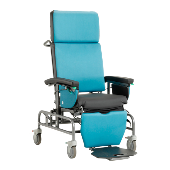
- Page 1 Positioning tilt-in-space Chair Optimum Posturo-pedic Series 1400 FOCUSED ON WHAT MATTERS lpamedical.com 2527, avenue Dalton, Québec (Qc) G1P 3S6 T 418 681-1313 1 800 663-4863 F 418 681-4488...
-
Page 2: A Word Of Thanks
If you have any questions after reading it, do not hesitate to contact your LPA representative or contact us directly via our website. We hope you enjoy your LPA Medical chair and we thank you for your business. Bryan Welch President LPA Medical inc. -
Page 3: Table Of Contents
List of Parts Exploded View REPLACEMENT PARTS AVAILABILITY POLICY LPA Medical’s replacement parts availability policy ensures parts for at least 10 years after the purchase of your LPA product, which makes it: An eco-friendly purchase. If something breaks, you know that •... -
Page 4: General Information
LPA chair. LPA Medical Inc. accepts no responsibility for any breakage, incident, injury, damage or accident caused by an error of use, negligence to maintain the chair and maintain it in a safe and functional state, through any unauthorized modification of the chair, failure to follow instructions ... -
Page 5: Safety Measures
In addition, LPA chairs are not designed for outdoor use. The Optimum 1400 chair must be used with accessories specifically designed for it by LPA Medical Inc. It must be used in accordance with recognized health and safety practices. -
Page 6: Inspection Before Use
INSPECTION BEFORE USE The chair is shipped fully-assembled. It must be inspected when unpackaged and you must notify your supplier if there is any damage or missing parts/accessories so that corrections are made before taking possession. RISK PREVENTION Always apply the brakes when the wheelchair is not moving and for any transfer or repositioning maneuver. -
Page 7: Improper Uses
IMPROPER USES Manipulating the chair without proper training. • Wheeling the chair outside of designated areas. • Wheeling the chair without using the directional wheel. • Using it for a patient without professional approval. • Making adjustments that require frequent repositioning. •... -
Page 8: Adjustment And Operating Instructions
ADJUSTMENT AND OPERATING INSTRUCTIONS WHEELS The Optimum 1400 is equipped with 3 casters with red lever-activated brakes and a green lever-activated directional wheel. Applying the brakes 1. Apply pressure with your foot at the edge of the red activation levers on the two rear wheels and front left wheel. - Page 9 WHEELS (continuation) Using the directional wheel’s activation lever The directional wheel is located on the front right and has a green activation lever. 1. Apply pressure with your foot on the lower end of the green activation lever to fix the direction. 2. Apply pressure with your foot on the top of the green activation lever to release the direction.
-
Page 10: Seat Depth
SEAT DEPTH A positioning professional must adjust the seat depth beforehand according to the person’s morpho- logical measurements. WARNING: THE BRAKES MUST BE APPLIED BEFORE ANY HANDLING. Seat depth adjustment 1. Pull the activation lever located at the front left of the seat. 2. -
Page 11: Tilting
TILTING The seat tilts in conjunction with the backrest and the armrests. A gas cylinder under the seat is connected to three activation levers. One lever is located on the far left on the push bar, and the others are under each of the armrests. - Page 12 TILTING (continuation) VARIATION: Tilting from the side 1. Stand on the left side of the chair at the patient’s side. 2. Grasp the front of the armrest with your left hand. 3. Using your right hand, activate the activation lever on the far left of the push bar.
-
Page 13: Elevating Legrest
ELEVATING LEGREST The angle of the elevating legrest can be adjusted from 80 to 132 degrees. It is equipped with cushioned calf pads and an adjustable full-width footrest. Legrest use and adjustment 1. Lift the patient’s legs slightly. 2. Detach the restraining strap from the footrest and lower it. - Page 14 ELEVATING LEGREST (continuation) Length compensation based on the angle 1. Use the rack-and-pinion activation lever located on the left side of the calf supports to lengthen the legrest by moving the footrest. Note that the lengthening must be proportional to the angle selected. The right configuration keeps the thighs on the seat and the feet flat on the footrests.
- Page 15 ELEVATING LEGREST (continuation) Legrest storage for upright transfer 1. Pull the D-shaped activation handle. 2. Push the legrest using the open footrest. 3. Push under the seat as much as possible. 4. Lift the person’s legs slightly so that you can fold the footrest. 5.
-
Page 16: Backrest
BACKREST The backrest angle improves the Optimum chair’s comfort for resting periods. It can be adjusted from 102 to 145 degrees from the seat and 175 degrees from the ground if the tilt is at its maximum. It is important to tilt the chair before tilting the backrest to prevent the patient from slipping. - Page 17 BACKREST (continuation) Returning the backrest 1. Stand on either side of the chair. 2. First, reduce the seat tilt to approximately 5 to 7 degrees from the floor (especially if the backrest is at full tilt or the patient is heavy). 3. If you are on the left of the wheelchair, press the activation lever under the armrest with your right hand while tilting the...
-
Page 18: Adjustable And Retractable Armrests
ADJUSTABLE AND RETRACTABLE ARMRESTS The armrests are height-adjustable from 3 ½” (9 cm) to 8 ½” (21.5 cm) from the seat in 1»(2.5 cm) increments. They can also be lowered to the seat level to facilitate transfers and patient access. Height adjustment and full clearance 1. -
Page 19: Articulated Headrest
ARTICULATED HEADREST The Optimum 1400’s optional articulated profiled headrest provides precise positioning for the head. It can be easily adjusted to meet most positioning needs. It is easily removable for transfer maneuvers. IMPORTANT: ALWAYS REMOVE THE HEADREST WHEN USING A TRANSFER AID. FAILURE TO DO SO MAY RESULT IN DAMAGE, INJURY OR DEATH. Headrest installation 1. -
Page 20: Adjustable Side Wings
ADJUSTABLE SIDE WINGS The optional adjustable side wings are adjustable both in height and width. Side wing installation 1. Insert the flat bar of the side wing into the mounting clip behind the upper section of the backrest, orienting the long, narrow part of the side wing downwards. 2. -
Page 21: Height Adjustment
ADJUSTABLE SIDE WINGS (continuation) Height adjustment 1. Loosen, but do not remove the two nuts from the flanges, so that they can be moved into the sliders of the upper section of the backrest. 2. Set at the appropriate height. 3. Retighten the nuts. Width adjustment 1. -
Page 22: Lateral Trunk Supports
LATERAL TRUNK SUPPORTS The optional lateral trunk supports are attached to the backrest structure and provide support to the chest by means of pivot-mounted cushions. Height adjustment 1. Loosen, but do not remove the two nuts from the flanges, so that they can be moved into the sliders of the upper section of the backrest. -
Page 23: Terms & Conditions
TERMS & CONDITIONS APPLICABLE TO PRODUCTS SOLD AFTER SEPTEMBER 1 2018 GENERAL All items & prices listed are subject to change without notice. We reserve the right to change and/or improve any product as deemed advisable without notification. Shipments will be made at prevailing prices at time of shipment. Additional freight fees at delivery may apply such as handling and/or liftgate and is the sole responsibility of the buyer unless otherwise specified beforehand. -
Page 24: General Warranty
If service is required under this warranty, contact our Customer Service Department in writing, giving the following information: 1. Model or part number involved. 2. Date of purchase, including LPA MEDICAL invoice or acknowledgement number. 3. A description of the problem. -
Page 25: Exclusions
EXCLUSIONS Normal wear and tear. • Accidental damage including fire and water. • Fabric facing and metal oxidation (rust), including damages caused • by power washers and wheelchair washing machines. Unauthorized modifications or repairs made or attempted. • Damage resulting from abuse, abnormal or unreasonable use. • 07-2019... -
Page 26: List Of Parts
LIST OF PARTS Code Description 1B3600 Thoracic Support, with Hardware B2-17-DR Side Booster Cushion, Right B2-17-GA Side Booster Cushion, Left 1B4100 Side Booster Support OP-0810 Adjustment Receptacles, with Hardware AB-07 Cervical Bracelet Support for 1400, Black B2-14 Adjustable Headrest Cushion 1B2900 Support for Adjustable Headrest, with Hardware SU-05... - Page 27 Code Description QCL50003 Curve Handleand Long Cable, with Hardware QCL50001 Straight Handleand Long Cable, with Hardware 1C1300 Arm Support Support, with Hardware 1A2418 Seat Suspension Support for Optimum 1400 - 18" 1A2420 Seat Suspension Support for Optimum 1400 - 20" 1A2422 Seat Suspension Support for Optimum 1400 - 22"...
-
Page 28: Exploded View
VUE ÉCLATÉE VUE ÉCLATÉE EXPLODED VIEW EXPLODED VIEW 63 64 65 66 67... - Page 29 33 34 35 29 29...
Need help?
Do you have a question about the Optimum Posturo-pedic 1400 Series and is the answer not in the manual?
Questions and answers