Table of Contents
Advertisement
Quick Links
Advertisement
Table of Contents

Related Manuals for Gantner Q Series


Summary of Contents for Gantner Q Series
- Page 1 Manual Q.bloxx Vers. No. 6.1...
- Page 2 Gantner Instruments GmbH. An exception is the making of a copy of software for one's own use for backup purposes, where this is technically possible and recommended by us.
-
Page 3: Table Of Contents
Connecting the power supply ..........28 Fitting and removal of modules from bases......30 Connecting interfaces ............31 4.4.1 Connecting modules to Q.gate ..........31 4.4.2 Connecting modules to Q.pac..........32 4.4.3 Connecting Q.gate/Q.pac via Ethernet to a PC/PLC..... 34 Q.series Gantner Instruments GmbH... - Page 4 4.4.4 Using the RS-232 interface of Q.gate or Q.pac ....35 4.4.5 Connecting modules directly to a PC/PLC ......36 Synchronization of several systems ........38 4.5.1 Connection of a radio receiver for time signals....41 4.5.2 Connection of a GPS receiver ..........41 Module flashing frequency ..........
- Page 5 Digital input and output ............91 4.24 Q.bloxx D104: connecting digital inputs ......94 4.24.1 Digital input................94 4.25 Q.bloxx D105: connecting digital outputs......96 4.25.1 Digital output................ 96 4.26 Q.bloxx D107: Connecting digital inputs ......97 4.26.1 Digital input................97 Q.series Gantner Instruments GmbH...
- Page 6 Configuration ............ 101 Installing the test.commander ........... 102 Using test.commander ............103 5.2.1 Linking test.commander via Ethernet (TCP/IP) ....103 5.2.2 test.commander and the serial (service) interface .... 105 5.2.3 Creating a project for configuration ........106 Configuring analog inputs ..........107 5.3.1 Setting sensor parameters..........
- Page 7 Sensor scaling ..............144 6.4.1 Scaling of voltage signals and strain-gauge bridges ..144 6.4.2 Scaling strain gauges ............145 Current measurement with an external shunt....147 Measuring with thermocouples ......... 148 International Sales and Service ......149 Q.series Gantner Instruments GmbH...
- Page 8 Vers. No. 6.1 Released: 25/04/2017...
-
Page 9: Safety Information
In this case contact your customer consultant or Gantner Instruments GmbH. Personnel The installation, operation and maintenance of the modules or devices must only be carried out by competent persons. -
Page 10: Special Risks
Safety Information accident prevention regulations, guidelines and accepted engi- neering rules. They must be able to reliably assess the results of their work and must be familiar with the contents of this manual. Electrical connections must only be carried out by specialist per- sonnel trained for the task. -
Page 11: Disposal
Never attempt to repair nor to again operate devices which are defective, have developed a fault or are damaged. In this case it is essential to contact your customer consultant or Gantner Instruments GmbH. Disposal... - Page 12 Safety Information Vers. No. 6.1 Released: 25/04/2017...
-
Page 13: Labels And Warning Information
Meaning: Modules with this symbol are intended for the connec- tion of high voltage. The maximum admissible voltage is also given. Symbol: Meaning: High voltage may be present on the module connec- tions. Connection may only be made with the insulated connect- ing plugs provided. Q.series Gantner Instruments GmbH... -
Page 14: Labels In This Manual
Labels and warning information Labels in this manual To simplify reading this manual we use – along with the warning information given above – the following labels and notation: IMPORTANT Paragraphs with this symbol give important information about the product or about using the product. Contains application hints and other particularly useful informa- tion. -
Page 15: Introduction
Introduction Introduction Dear Customer, Thank you for purchasing a product in the Q.series from Gantner Instruments GmbH. We are sure that you have obtained an excel- lent product which will enable you to make fast and reliable mea- surements with low measurement uncertainties. -
Page 16: The Documentation In The Q.bloxx Range
Gantner CD or on our home page www.gantner-instruments.com. You will find this manual also as a PDF file on our home page and on the Gantner CD enclosed with your module or which you can order free of charge from Gantner Instruments GmbH. About this manual This manual describes the installation, initial operation and the configuration of the modules Q.bloxx A101, A102, A103, A104,... -
Page 17: System Description
16 modules also takes place through the extension socket. You can communicate via Ethernet with the connected modules from the Q.gate Test Controller. The maximum cable length between the measurement modules and the Q.gate depends on the desired baud rate: Q.series Gantner Instruments GmbH... - Page 18 Introduction Cable length in meters Maximum baud rate 1000 < 500 kBaud < 1500 kBaud < 6000 kBaud >6 to 24 MBaud You can insert the Q.gate Test Controller alternatively into the base to the left or right of the Q.bloxx modules (first or last base). Since the Q.gate Test Controller has a bus termination, it must be located on the end of the line and must not be positioned between the modules.
-
Page 19: Operating The Modules Via Q.pac
16 real variables (10 kHz) Ethernet data throughput (transmission rate with online transfer) 128 real variables (300 Hz) EtherCAT data throughput (transmission rate) 256 real variables (10 kHz) Ethernet, EtherCAT, USB, Interfaces RS-232, 4 UARTs Max. number of slaves (Q.bloxx) Q.series Gantner Instruments GmbH... -
Page 20: Operating The Modules Without Test Controller
You can connect the modules directly to a PC or PLC via the RS- 485 interface on the modules. The following protocols are avail- able: • Gantner's own fast binary protocol. The configuration here takes place via the programs test.commander or ICP 100. • Modbus RTU for reading and writing variables via registers. -
Page 21: Connecting The Modules
Configuring the operating The configuration of the operating mode occurs using the DIP switches in the base (Fig. 4-1). DIP switch 7 is currently not mode assigned any function and is reserved for later expansions. Q.series Gantner Instruments GmbH... -
Page 22: Hot Swap (Factory Setting)
Connecting the modules → Connecting the base Fig. 4-1 DIP sw itches in the base, all DIP sw itches except the first one are OFF (address 1, hot swap activated). 4.1.1 Hot swap (factory setting) Hot swap, i.e. the loading of the configuration from the socket EPROM (boot configuration), enables you to replace a defective module by one of the same type without having to carry out a con- figuration. -
Page 23: Setting The Address (Optional)
DIP switch or via software, because otherwise sev- eral modules use the same address (default: 1) and are therefore not capable of measurement within a data bus; refer to Q.series Gantner Instruments GmbH... -
Page 24: Activating The Terminating Resistances
Connecting the modules → Connecting the base Chapter 5, Configuration, Section 5.2. Also for a configuration via the DIP switches an address set via the PC is retained in the module and is used again when the DIP switches are set to the address 0. -
Page 25: Mounting/Removing Bases
Then push the base onto any further existing bases to the left. There should be no intervening space between the bases, so press the right base firmly onto the left one. Q.series Gantner Instruments GmbH... -
Page 26: Q.bloxx Extension Socket Qes
Connecting the modules → Connecting the base Fig. 4-3 Connecting several bases. To remove, insert a narrow screwdriver into the hole at the lower end, press the screwdriver upwards on the handle to push the metal clip in the latching cam downwards and from below pull the base from the mounting rail to the front. - Page 27 (cross) the UART lines via the DIP switches on the extension socket. This variant is, for example, suitable for the connec- tion of a Q.pac Test Controller. DIP switch settings The extension socket is operated in one of two modes depending on the application: Q.series Gantner Instruments GmbH...
-
Page 28: Connecting The Power Supply
Connecting the modules → Connecting the power supply 1. The interface lines are connected through 1:1 from left to right. The DIP switches 1 to 4 are OFF and the DIP switches 5 to 8 are ON (factory setting). 2. The interface lines are crossed. The DIP switches 1 to 4 are ON and the DIP switches 5 to 8 are OFF. - Page 29 Q.bloxx Extension Socket QES. ➡ The extension socket only supplies the module situated to the right of it and the modules located to the left of it require a power supply via the socket located on the far left. Q.series Gantner Instruments GmbH...
-
Page 30: Fitting And Removal Of Modules From Bases
Connecting the modules → Fitting and removal of modules from bases Fitting and removal of modules from bases Once you have mounted the bases, you can plug in the modules. To do this, hold the module so that it latches into the base latch- ing cam below and then press it into the base with a slight rotary movement until the upper latching cam locks. -
Page 31: Connecting Interfaces
Q.bloxx module. However, only use the far left or far right base, because the module has integral terminating resistances and therefore terminates this end of the interface line. Any set base address is ignored by the Test Controller. Q.series Gantner Instruments GmbH... -
Page 32: Connecting Modules To Q.pac
Connecting the modules → Connecting interfaces IMPORTANT Make sure that the terminating resistances at the (other) ends of the interface cables are activated. No resistances should be acti- vated in the base of the Q.gate. They are permanently fitted in the Q.gate Test Controller and are always active. - Page 33 Sync A Input/output for synchronization, e.g. with another Test Controller Sync B Pin assignment for plug-in terminal X3 0 V, GND Digital Input 1 Digital Input 2 Digital Input 3 Digital Input 4 Digital Output 1 Q.series Gantner Instruments GmbH...
-
Page 34: Connecting Q.gate/Q.pac Via Ethernet To A Pc/Plc
Connecting the modules → Connecting interfaces Pin assignment for plug-in terminal X3 Digital Output 2 Digital Output 3 Digital Output 4 +10 to 30 V for digital inputs/outputs Fig. 4-10 Pin assignment for the plug-in terminals of the Q.pac Test Controller. -
Page 35: Using The Rs-232 Interface Of Q.gate Or Q.pac
Section 4.5.2, page 41. The RS-232 interface of the Q.gate Test Controller is located below the USB interface at the front. For the link to a PC you require the supplied cable with the 3.5 mm stereo jack plug. Q.series Gantner Instruments GmbH... -
Page 36: Connecting Modules Directly To A Pc/Plc
You can connect modules directly to an RS-485 interface via the base connections UART 1A and UART 1B. The following protocols are available: • The Gantner fast binary protocol for the programs ICP 100 and test.commander. • Modbus RTU for reading and writing variables via registers. - Page 37 The modules cannot be directly connected to an RS-232 inter- face. Use an adapter if necessary for converting an RS-232 inter- face to RS-422 or RS-485, e.g. the interface converter ISK 101 from Gantner. Refer also to Section 6.1 on page 135. Pin assignment Sync A...
-
Page 38: Synchronization Of Several Systems
Connecting the modules → Synchronization of several systems 2. Start the software and select the Utilities > Module setup assistant Another program window opens. 3. Select Options > Communication settings. 4. Under Interface type select the RS-232 direct connection and under ComPort the PC connection you are using. 5. - Page 39 Test Controller (also to Q.gate) (Variant 3b). 4. You define a PC as an SNTP time server which can distribute the NTP time stamp to all Q.gate or Q.pac Test Controllers (dark blue path in Fig. 4-13). Q.series Gantner Instruments GmbH...
- Page 40 Connecting the modules → Synchronization of several systems Fig. 4-13 Possible types of time synchronization. The absolute accuracy of the time information depends on the method used. If you do not want to use or cannot use any time synchronization lines, e.g. because the spacing of the systems is too large, you must expect greater deviations.
-
Page 41: Connection Of A Radio Receiver For Time Signals
The configuration is carried out using the program test.com- mander and the menu Settings > Synchronization > Sync. settings. Protocol; refer also to Section 5.8.3.3, page 123. Use the variable GetPositioningData to evaluate the individual data items of your GPS receiver. Q.series Gantner Instruments GmbH... -
Page 42: Module Flashing Frequency
Connecting the modules → Module flashing frequency Module flashing frequency The modules have three LEDs: one blue LED on the upper edge and one red LED per connector strip. In normal operation the blue LED lights, but the red LEDs do not light. Depending on the error, the LED of the affected connector strip or the blue LED lights or all LEDs flash in a certain order. -
Page 43: Problems During Data Transmission
3. Is wiring of the interface connections correct? Then restart the system (by switching off, waiting one minute and then switching on again). If these measures do not remedy the error, then contact your customer consultant or Gantner Instruments GmbH directly. 4.6.5... -
Page 44: The Modules And Their Connection Options
Connecting the modules → The modules and their connection options The modules and their connection options Modules: Signal inputs Voltage Current Potentiometer Resistance Pt100, Pt1000 Thermocouple (Strain gauges) full + half bridge Strain-gauge quarter bridge Inductive full and half bridge LVDT, RVDT ®... - Page 45 Digital output: frequency, pulse width Digital output: Status Number of channels up to Data rate (in Hz) 100 k 10 k 100 k 100 k 10 k 10 k 100 k For description refer to page Q.series Gantner Instruments GmbH...
-
Page 46: Q.bloxx A101: Connecting Sensors And I/O
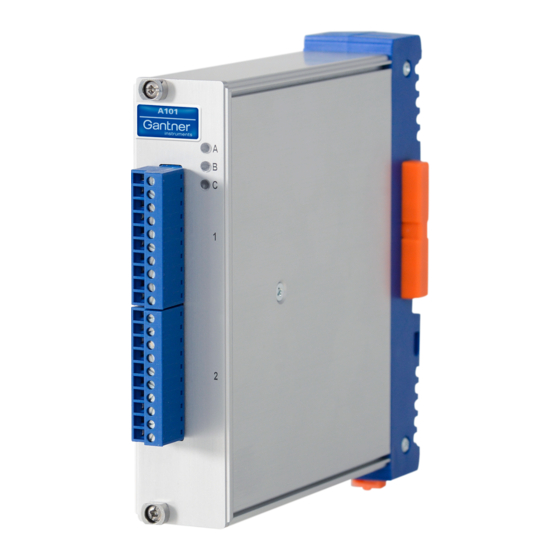
Connecting the modules → Q.bloxx A101: Connecting sensors and I/O Q.bloxx A101: Connecting sensors and I/O The Q.bloxx Module A101 has two electrically isolated analog inputs and two digital inputs or outputs. The pin assignment of the two connector strips is identical and the connection terminals have numbers for identifying the connections. -
Page 47: Current
Fig. 4-21 A101, measurement w ith potentiometers. 4.8.4 Resistance, Pt100, Pt1000 You can connect resistances and Pt100/1000 probes in two-wire or four-wire circuits. You specify the selected type of circuit during the module configuration (Type column). Q.series Gantner Instruments GmbH... -
Page 48: Thermocouple
The plug can be obtained under the designation Q.bloxx Terminal CJC-A101 from Gantner Instruments GmbH. You can connect the following types of thermocouple: B, E, J, K, L, N, R, S, T and U. Alternatively, you can also use two thermocouples or a reference temperature source. -
Page 49: Strain-Gauge Quarter Bridges
The plug can be obtained under the designation Q.bloxx Terminal B4/120-A101 with120 or B4/350-A101 with 350 from Gantner Instruments GmbH. The bridge excitation voltage is 2.5 V. IMPORTANT The plug must have the same resistance values as the strain gauges used, because otherwise no measurement is possible.... -
Page 50: Digital Input And Output
Connecting the modules → Q.bloxx A101: Connecting sensors and I/O 8 (+) IEPE 7 (GND) ® Fig. 4-26 A101, measurement w ith IEPE or ICP sensors. 4.8.9 Digital input and output On each connecting plug a contact is available for an input or out- put. -
Page 51: Q.bloxx A102: Connecting Sensors And I/O
Pin assignment for Q.bloxx Module A102. Further information on transducers and sensors can also be found in Chapter 6 ff. page 135. 4.9.1 Voltage You can measure voltages of up to 10 V via Plug 2. Q.series Gantner Instruments GmbH... -
Page 52: Current
Connecting the modules → Q.bloxx A102: Connecting sensors and I/O IMPORTANT Voltages which exceed the admissible limits produce incorrect measurement data, because the inputs are protected against overvoltages and limit the input voltage. 8 (+) 7 (GND) Fig. 4-29 A102, measurement of voltage, Plug 2. 4.9.2 Current A shunt resistance of 50 ... -
Page 53: Strain-Gauge Quarter Bridges
The plug can be obtained under the designation Q.bloxx Terminal B4/120-A102 with120 or B4/350-A102 with 350 from Gantner Instruments GmbH. The bridge excitation voltage is switched via software between 1 V, 2.5 V, 5 V and 10 V. -
Page 54: Digital Input And Output
Connecting the modules → Q.bloxx A102: Connecting sensors and I/O 1 (+) 1 (+) 2 (–) 2 (–) Fig. 4-34 A102, output of voltage or current, Plug 1. 4.9.7 Digital input and output Contacts for four inputs and two outputs are available on Plug 1. Input Output 7, 8... -
Page 55: Q.bloxx A103: Connecting Sensors And I/O
4– Fig. 4-36 Pin assignment for Q.bloxx Module A103. Further information on transducers and sensors can also be found in Chapter 6 ff. page 135. 4.10.1 Voltage You can measure voltages of up to ±10 V. Q.series Gantner Instruments GmbH... -
Page 56: Current
Connecting the modules → Q.bloxx A103: Connecting sensors and I/O IMPORTANT Voltages which exceed the admissible limits produce incorrect measurement data, because the inputs are protected against overvoltages and limit the input voltage. 3, 5, 7, 9 (+) 4, 6, 8, 10 (–) Fig. -
Page 57: Q.bloxx A104: Connecting Sensors
4– Fig. 4-40 Pin assignment for Q.bloxx Module A104. Further information on transducers and sensors can also be found in Chapter 6 ff. page 135. 4.11.1 Voltage You can measure voltages of up to 80 mV. Q.series Gantner Instruments GmbH... -
Page 58: Thermocouple
Terminal CJC-A104 from Q.bloxx Gantner Instruments GmbH. You can connect the following types of thermocouple: B, E, J, K, L, N, R, S, T and U. Alternatively, you can also use two thermocouples or a reference temperature source. -
Page 59: Q.bloxx A105: Connecting Sensors
You can connect resistances and Pt100/1000 probes in two-wire, three-wire or four-wire circuits. However, you must in each case connect all the terminals, i.e. you specify the circuit used for the type of circuit when configuring the module (Type column), but Q.series Gantner Instruments GmbH... - Page 60 Connecting the modules → Q.bloxx A105: Connecting sensors with two and three-wire circuits the unused terminals must be bridged. 4-wire circuit 2, 7 3, 8 4, 9 5, 10 (GND) 2-wire circuit 3-wire circuit 2, 7 2, 7 3, 8 3, 8 4, 9 4, 9...
-
Page 61: Q.bloxx A106: Connecting Sensors And I/O
Chapter 6 ff. page 135. 4.13.1 Full and half-bridge transducers With (resistive) full bridges (strain-gauge full bridges) all connec- tions are occupied. If the sensor has no sensing leads, you specify this during the module configuration (Type column). With half Q.series Gantner Instruments GmbH... -
Page 62: Strain-Gauge Quarter Bridge
The plug can be obtained under the designation Q.bloxx Terminal B4/120-A106 with120 or B4/350-A106 with 350 from Gantner Instruments GmbH. The bridge excitation voltage can be 2.5 V or 5 V (DC or CF). IMPORTANT The plug must have the same resistance values as the strain gauges used, because otherwise no measurement is possible.... -
Page 63: Lvdt, Rvdt
(DC) or 600 Hz carrier frequency. 5 (+) 6 (–) Fig. 4-49 A106, measurement w ith LVDTs and RVDTs. 4.13.5 Analog output An analog voltage output is available on each connecting plug. 3 (+) 4 (GND) Fig. 4-50 A106, analog output. Q.series Gantner Instruments GmbH... -
Page 64: Digital Input And Output
Connecting the modules → Q.bloxx A106: Connecting sensors and I/O 4.13.6 Digital input and output On each connecting plug two contacts are available for an input or output. You can use the appropriate function depending on the wiring. Input Output 1, 2 1, 2 Fig. -
Page 65: Q.bloxx A107: Connecting Sensors
5, 10 (GND) Fig. 4-52 Pin assignment for Q.bloxx Module A107. Further information on transducers and sensors can also be found in Chapter 6 ff. page 135. 4.14.1 Voltage You can measure voltages of up to 10 V. Q.series Gantner Instruments GmbH... -
Page 66: Current
Connecting the modules → Q.bloxx A107: Connecting sensors IMPORTANT Voltages which exceed the admissible limits produce incorrect measurement data, because the inputs are protected against overvoltages and limit the input voltage. 2, 7 (+) 5, 10 (GND) Fig. 4-53 A107, measurement of voltage. 4.14.2 Current A shunt resistance of 50 ... -
Page 67: Thermocouple
The plug can be obtained under the designation Q.bloxx Terminal CJC-A107 from Gantner Instruments GmbH. You can connect the following types of thermocouple: B, E, J, K, L, N, R, S, T and U. Alternatively, you can also use two thermocouples or a reference temperature source. -
Page 68: Strain-Gauge Half And Quarter Bridges
The plug can be obtained under the designation Q.bloxx Terminal B4/120-A107 with120 or B4/350-A107 with 350 from Gantner Instruments GmbH. The bridge excitation voltage is 2.5 V. IMPORTANT... -
Page 69: Q.bloxx A108: Connecting Sensors And I/O
4– Fig. 4-60 Pin assignment for Q.bloxx Module A108. Further information on transducers and sensors can also be found in Chapter 6 ff. page 135. 4.15.1 Voltage You can measure voltages of up to 10 V. Q.series Gantner Instruments GmbH... -
Page 70: Current
Connecting the modules → Q.bloxx A108: Connecting sensors and I/O IMPORTANT Voltages which exceed the admissible limits produce incorrect measurement data, because the inputs are protected against overvoltages and limit the input voltage. 3, 5, 7, 9 (A 4, 6, 8, 10 (A –) Fig. -
Page 71: Q.bloxx A109: Connecting I/O And Outputs
Since the inputs and outputs of this module are electrically iso- lated from the supply voltage, you must also connect 0 V for the inputs and 0 V and a supply voltage (+V) for the outputs. Q.series Gantner Instruments GmbH... -
Page 72: Analog Output, Plug 2
Connecting the modules → Q.bloxx A109: Connecting I/O and outputs Input Output 2, 3, 4, 5 6, 7, 8, 9 10 (0V) 10 (0V) Fig. 4-65 A109, digital input and output, Plug 1. The digital input is active (high level) when the applied signal voltage lies above the (programmable) threshold. -
Page 73: Q.bloxx A111: Connecting Sensors And I/O
10 NC Fig. 4-67 Pin assignment for Q.bloxx Module A111. Further information on transducers and sensors can also be found in Chapter 6 ff. page 135. 4.17.1 Voltage You can measure voltages of up to 10 V. Q.series Gantner Instruments GmbH... -
Page 74: Iepe/Icp ® Sensor
Connecting the modules → Q.bloxx A111: Connecting sensors and I/O IMPORTANT Voltages which exceed the admissible limits produce incorrect measurement data, because the inputs are protected against overvoltages and limit the input voltage. 2, 7 (+) 4, 9 (–) Fig. 4-68 A111, measurement of voltage. -
Page 75: Q.bloxx A116: Connecting Sensors
Sen7– Sig7– A30 – B30 – A31 U B31 U Exc8+ Sig8+ A32 U B32 U Exc8– Sen8+ A33 U B33 U Sen8– Sig8– A34 – B34 – Fig. 4-70 Pin assignment for Q.bloxx Module A116. Q.series Gantner Instruments GmbH... - Page 76 Connecting the modules → Q.bloxx A116: Connecting sensors (B7) SIG+ (B8) SEN+ (A7) EXC+ (B9) SIG- (A9) SEN- (A8) Q.bloxx 116 Junction Box EXC- (A3) EXC+ (B4) SEN+ (B3) SIG+ (A4) EXC- (A5) SEN- (B5) SIG- Fig. 4-71 Terminal assignment for the Q.bloxx Connection Terminal CT A116.
- Page 77 Pink Exc+ Pair 1 Pink/black Exc– Orange/white Sen+ Pair 2 Grey/white Sen– White/red Sig+ Pair 3 White/blue Sig– Light green/red Exc+ Pair 1 Green/blue Exc– Sen+ Pair 2 Red/black Sen– Purple Sig+ Pair 3 Purple/white Sig– Q.series Gantner Instruments GmbH...
-
Page 78: Full And Half-Bridge Transducers
Connecting the modules → Q.bloxx A116: Connecting sensors Input/ Sensor connec- cable Pairing Cable color Socket connection tion bundle Green Exc+ Pair 1 Green/black Exc– Light blue/green Sen+ Pair 2 Light blue/yellow Sen– Light yellow Sig+ Pair 3 Light yellow/red Sig–... -
Page 79: Strain-Gauge Quarter Bridge
120 and 350 completion resistances are present in the module and only need to be activated. In addition you can activate the inter- nal shunt resistance for test purposes. Q.series Gantner Instruments GmbH... - Page 80 Connecting the modules → Q.bloxx A116: Connecting sensors ; with 350 sensor resis- The bridge excitation voltage is 2 V tance you can also use 4 V Exc– Exc– Sig+ Sig+ Ω Ω Exc+ Exc+ Input 1 Input 2 Input 3 Input 4 Exc+...
-
Page 81: Activating The Shunt Resistance
Open the module settings dialog(Fig. 4-76), activate the tab Vari- able definition and click in the column Format/balance. The dialog of Fig. 4-77 opens. Fig. 4-76 Module configuration dialog. Fig. 4-77 Dialog for format settings. Q.series Gantner Instruments GmbH... - Page 82 Connecting the modules → Q.bloxx A116: Connecting sensors Fig. 4-78 Dialog for shunt activation. Manual activation Define the Direction for the variable on Input/output (Fig. 4- 77) and click on Shunt cal. Activate Control computer in the dialog (Fig. 4-78). Setting a value of 16 for the variable (the channel) activates the shunt and 0 deactivates it again.
-
Page 83: Q.bloxx A123: Connecting Sensors
). With a screwdriver press on the white opener to remove the connection. 2, 7 (+) 1– 4, 9 (–) 2, 7 (+) ext. 2– 4, 9 (-) 10 NC 3– 4– 10 NC Fig. 4-79 Pin assignment and plugs for the Q.bloxx module A123. Q.series Gantner Instruments GmbH... -
Page 84: Voltage
Connecting the modules → Q.bloxx A123: Connecting sensors Further information on transducers and sensors can also be found in Chapter 6 ff. page 135. 4.19.1 Voltage You can measure voltage differences of up to ±10 V. The voltage level (the potential) may be up to 1200 V IMPORTANT Voltage differences which exceed the admissible limits produce incorrect measurement data, because the inputs are protected... -
Page 85: Q.bloxx A124: Connecting Sensors
With a screwdriver press on the white opener to remove the connection. 2, 7 (+) 4, 9 (–) 1– 2, 7 (+) 4, 9 (–) 2– 3– 4– Fig. 4-82 Pin assignment for Q.bloxx Module A104. Q.series Gantner Instruments GmbH... -
Page 86: Voltage
Connecting the modules → Q.bloxx A124: Connecting sensors Further information on transducers and sensors can also be found in Chapter 6 ff. page 135. 4.20.1 Voltage You can measure voltage differences of up to ±80 mV. The volt- age level (the potential) may be up to 1200 V IMPORTANT Voltage differences which exceed the admissible limits produce incorrect measurement data, because the inputs are protected... -
Page 87: Q.bloxx A127: Connecting Sensors
). With a screwdriver press on the white opener to remove the connection. 2, 7 (+) 1– 4, 9 (–) 2, 7 (+) ext. 2– 4, 9 (-) 10 NC 3– 4– 10 NC Fig. 4-85 Pin assignment and plugs for the Q.bloxx module A127. Q.series Gantner Instruments GmbH... -
Page 88: Voltage
Connecting the modules → Q.bloxx A127: Connecting sensors Further information on transducers and sensors can also be found in Chapter 6 ff. page 135. 4.21.1 Voltage You can measure voltage differences of up to ±1200 V. Here, var- ious input voltage ranges from ±40 V to ±1200 V are possi- ble. -
Page 89: Q.bloxx A128: Connecting Sensors
). With a screwdriver press on the white opener to remove the connection. 2, 7 (+) 1– 4, 9 (–) 2– 10 NC 3– 4– 10 NC Fig. 4-88 Pin assignment and plugs for the Q.bloxx module A128. Q.series Gantner Instruments GmbH... -
Page 90: Voltage
Connecting the modules → Q.bloxx A128: Connecting sensors Further information on transducers and sensors can also be found in Chapter 6 ff. page 135. 4.22.1 Voltage You can measure voltages of up to ±1200 V . Here, various input voltage ranges from ±40 V to ±1200 V are possible. -
Page 91: Q.bloxx D101: Connecting I/O
Since the inputs and outputs of this module are electrically isolated from the supply voltage, you must also connect 0V for the inputs and 0 V and a supply voltage (+V) for the outputs. Q.series Gantner Instruments GmbH... - Page 92 Connecting the modules → Q.bloxx D101: Connecting I/O Input Output 2, 3, 4, 5 6, 7, 8, 9 10 (0V) 10 (0V) Fig. 4-91 D101, digital input and output. The digital input is active (high level) when the applied signal voltage lies above the (programmable) threshold.
- Page 93 Up/down counter or measurement of frequency and direction with static direction signal, 2 signals Measurement of frequency and direction or up/down counter with 2-channel frequency signal (90° phase delay) Measurement of frequency and direction or up/down counter with 4-channel frequency signal Index Index enable Q.series Gantner Instruments GmbH...
-
Page 94: Q.bloxx D104: Connecting Digital Inputs
Connecting the modules → Q.bloxx D104: connecting digital inputs 4.24 Q.bloxx D104: connecting digital inputs The Q.bloxx Module D104 has sixteen digital inputs. The pin assignment of the two connector strips is identical and the con- nection terminals have numbers for identifying the connections. You will find the associated figures in each case at the same place in the circuit diagrams, for example each of the figures quoted in the second place belong to one possible connection method. - Page 95 Connecting the modules → Q.bloxx D104: connecting digital inputs The digital input is active (high level) when the applied signal voltage lies above the (programmable) threshold. Q.series Gantner Instruments GmbH...
-
Page 96: Q.bloxx D105: Connecting Digital Outputs
Connecting the modules → Q.bloxx D105: connecting digital outputs 4.25 Q.bloxx D105: connecting digital outputs The Q.bloxx Module D105 has sixteen digital outputs. The pin assignment of the two connector strips is identical and the con- nection terminals have numbers for identifying the connections. You will find the associated figures in each case at the same place in the circuit diagrams, for example each of the figures quoted in the second place belong to one possible connection method. -
Page 97: Q.bloxx D107: Connecting Digital Inputs
4.26.1 Digital input On each connecting plug contacts for three inputs are available. You can use the inputs as a differential input or as a ground-ref- erenced (single-ended) input. Since in each case the inputs termi- Q.series Gantner Instruments GmbH... - Page 98 Connecting the modules → Q.bloxx D107: Connecting digital inputs nals are electrically isolated from one another and from the sup- ply voltage, you also have to connect GND (0 V) even with differential inputs. A supply voltage (+V) of 5 V and max. 150 mA per terminal is available for supplying the connected sensors.
- Page 99 D107, sensor w ith two signals (90° offset), single-ended or differential (input broken line). 0-Ref. 10 (GND, 0V) Fig. 4-100 D107, sensor w ith three signals (2 x 90° offset and zero reference), single-ended or differential (input broken line). Q.series Gantner Instruments GmbH...
- Page 100 Connecting the modules → Q.bloxx D107: Connecting digital inputs Vers. No. 6.1 Released: 25/04/2017...
-
Page 101: Configuration
• Enter the sensors used and their sensitivities to obtain an indication in the measured physical quantity. • Define computations, digital inputs/outputs, alarm monitor- ing, etc. • Activate all settings in the module and Test Controller. Q.series Gantner Instruments GmbH... -
Page 102: Installing The Test.commander
We recommend that you close all open programs before the installation. Insert the Gantner CD into your CD drive. In the standard config- uration Windows opens the CD automatically and a start window appears. If you have deactivated the Windows autostart function, find the file StartUp.exe in the main directory on the CD and give... -
Page 103: Using Test.commander
PC interface (a UDP Scan is executed) or directly enter a single address of Q.gate or Q.pac. If With the UPD Scan all devices in a network are addressed simultaneously. The scan is therefore executed very quickly. Q.series Gantner Instruments GmbH... - Page 104 Configuration → Using test.commander required, ask the network administrator to enable these scan methods and access of the program through the firewall to the Test Controllers. If you use, e.g. 15 seconds, for the Add. (itional) timeout, an attempt to establish connection is interrupted after this period.
-
Page 105: Test.commander And The Serial (Service) Interface
Test Controller and presents you with a dialog in which you can read out the existing settings (Read) or set a new Ether- net address (and subnet mask) or DHCP (Write). Cancel If you are not initially creating a project, close the starting dialog with Q.series Gantner Instruments GmbH... -
Page 106: Creating A Project For Configuration
Configuration → Using test.commander 5.2.3 Creating a project for configuration A project contains the hardware setup, the sensor and I/O set- tings present in the modules as well as the sensor signals used and computations, the so-called variables, which are to be output. Procedure 1. -
Page 107: Configuring Analog Inputs
Type. 2. Select Analog. Input. 3. Click in the column Variable name and allocate a name iden- tifying the signal from the connected sensor. 4. Click in the column Sensor and specify the type of sensor. Q.series Gantner Instruments GmbH... - Page 108 Configuration → Configuring analog inputs Depending on the type of module, you have various options available, e.g. Bridge for strain-gauge full and half-bridges, Pt100, Resistance for resistors or Voltage for voltage mea- surements and IEPE sensors. 5. Click in the column Type of and specify the type of circuit or further information about the sensor type.
-
Page 109: Carrier Frequency Synchronization (Q.bloxx A106)
Gantner programs. Specifying three decimal places displays, for example, the value 1234 as 1,234. -
Page 110: Zero Balancing/Taring The Sensor
Configuration → Configuring analog inputs supply lines and the signal inputs of different modules. This then leads to beats in the measurement signal. After selecting a carrier frequency, you have three methods of supply: 1. No sync.(hronization) This setting is practicable when you are only using one mod- ule with carrier frequency supply. - Page 111 5. Click on Direction and specify Input/Output for the channel so that control is possible (Fig. 5-3). 6. Click on Zero balance or Tare to configure the relevant pro- cess (Fig. 5-3). 7. Select the variable created above as the control variable (Fig. 5-4). Q.series Gantner Instruments GmbH...
-
Page 112: Sensor Scaling Over Several Points (Table)
Configuration → Configuring analog inputs Fig. 5-4 Setting up zero balance or tare. When the variable (Zero_tare in this example) has certain values, taring or zero balancing is carried out or an existing zero or tare value is deleted (undo zero balancing/taring): Value Function Perform taring when setting the value... - Page 113 6. Click on Linearize and select your unit. 7. Edit the existing values or generate further rows with New and specify the values for your sensor (Fig. 5-7). The rows are sorted based on the entered values. Q.series Gantner Instruments GmbH...
-
Page 114: Specifying Digital Inputs/Outputs
Configuration → Specifying digital inputs/outputs Fig. 5-7 Entering the scaling table. If the data are present in an Excel file, you can also import a file in the format Excel 97-2003-Workbook (*.xls). Alternatively to entering a unit in step 5, you can leave the elec- trical unit of the sensor as it is and enter the table in this unit, e.g. - Page 115 Status indicator: The output can be set via a command from the Test Controller, e.g. via a PROFIBUS-DP command. Click in the column Other and specify the type of alarm monitoring. 5. Click in the column Format/balance to specify the transfer format. Q.series Gantner Instruments GmbH...
-
Page 116: Configuring Analog Outputs
Configuration → Configuring analog outputs Since digital signals do not require any Decimal places, you can enter 0 here. 1 is sufficient for the Field length. With a digital input you can also specify a unit (optional). For several inputs/outputs and the type Status field (Type of column), as well as the transfer as a number (e.g. - Page 117 Test Controller through which the module is connected and an identifier for the relevant module. IMPORTANT If the modules are connected through a Test Controller, new module settings must also be updated there. Select or File Q.series Gantner Instruments GmbH...
-
Page 118: Defining Computations
Configuration → Defining computations > Write project (update) in the test.commander. The project file is in this case automatically updated. Defining computations In order to set parameters you should be connected to the mod- ule and have called the configuration program (ICP 100 which is started automatically by test.commander): Mark a module and select Configuration from the context menu or double click on a module or module signal (variable) to start the configuration pro-... -
Page 119: Specifying The Alarm Monitoring
Gantner programs. Specifying three decimal places dis- plays, for example, the value 1234 as 1,234. After closure of the dialog the number of transferred places and the unit are displayed in the column Format/balance, e.g. - Page 120 Configuration → Specifying the alarm monitoring All module signals are defined as variables. Therefore, for the entry activate the tab Variable definition in the configuration program. ➡ In order to monitor a limit and to output a level on a digital output when an alarm occurs, you can directly use the function of the digital output.
-
Page 121: Q.gate And Q.pac Settings
Using this parameter group you specify the speed of the data transmission on the individual interfaces (UARTs). The maximum possible speed depends on the overall length of the cable which is connected to the relevant interface. Q.series Gantner Instruments GmbH... -
Page 122: Host Interface
Configuration → Q.gate and Q.pac settings Cable length in meters Maximum baud rate 1000 < 500 kBaud < 1500 kBaud < 6000 kBaud >6 to 48 MBaud A change in the baud rate is also carried out automatically on the modules connected to the interface. - Page 123 Configuration → Q.gate and Q.pac settings Buffer pre-initialization In the Fast filling default setting each measurement transferred with a bit error leads to an error: the measurement is set to -1 (default setting for Filling pattern) and the error counter is set. This generally causes the test-rig to stop.
- Page 124 Configuration → Q.gate and Q.pac settings 1. Synchronization of several Q.pac Test Controllers through one sync line Connect the sync connections of the Test Controller through synchronization lines (plug-in terminal 2, connections 9 and 10; refer to Section 4.4.2, page 32). For this purpose use a screened cable with twisted cores if possible.
-
Page 125: Storage Settings (Only Q.pac)
Configuration → Q.gate and Q.pac settings Connect the time signal directly on all Test Controllers to the digital IOs (plug terminal 2, connections 9 and 10; refer to Section 4.4.2, page 32). Depending on the output signal, specify AFNOR via IOs or IRIG B003/B005 via IOs for Set- tings >... -
Page 126: Virtual Variable
Configuration → Q.gate and Q.pac settings Fig. 5-13 Dialog for specifying the time format. 5.8.6 Virtual variable With virtual variables you can carry out computations, evaluate trigger conditions or carry out assessments. The variables can be output like measurements or linked to other variables, measure- ments or digital I/Os. - Page 127 Configuration → Q.gate and Q.pac settings Fig. 5-14 Configuration dialog for a virtual variable. Click on, for example, Formula to enter a computation (Fig. 5- 15). Fig. 5-15 Defining a computation (formula). Vers. No. 6.1 Released: 25/04/2017...
- Page 128 Configuration → Q.gate and Q.pac settings In the dialog you have available all variables already defined (tab V1-10 and other tabs if more than ten variables have been defined). Click on one of the variables to insert it into the for- mula.
-
Page 129: Online Tools
Configuration → Online tools Online tools 5.9.1 Read data buffer (with measurements) or use File > Read online data buffer from con- Click on troller to be able to read out and view all values from the ring buffer. Fig. 5-16 Display of the buffer content w ith test.viewer. -
Page 130: Reading Module Information
Configuration → Online tools Fig. 5-17 Dialog for displaying the variable values. In the dialog click on Show online graphics to display the val- ues in a graph over time. 5.9.3 Reading module information Click on or use File > Read online module info from controller to be able to display information such as the address or serial number of your system. -
Page 131: Reading Status Information
Configuration 5.9.4 Reading status information Click on or use File > Read online status info from con- troller to display status information of your system. Fig. 5-19 Display of the status information. Q.series Gantner Instruments GmbH... -
Page 132: Firmware Update
ICP 100 or test.commander. Here, the program licenses apply to all versions of a program. If required, download the latest versions from our web site: www.gantner- instruments.com. You will find the programs under Software > Download. -
Page 133: Firmware Update For Modules
3. Search for the Test Controller or the modules: Find modules. 4. If the modules are connected via a Test Controller, in the next window mark the Test Controller to which the modules to be updated are connected and click on OK. Q.series Gantner Instruments GmbH... - Page 134 Configuration Vers. No. 6.1 Released: 25/04/2017...
-
Page 135: Functional Procedures
You will find further information on these topics and on connec- tion techniques in this section. 6.1.1 Interface converter Gantner Instruments GmbH offers you two different interface converters: 1. The compact interface converter ISK 200 (bench-top unit) The converter has an integrated power supply for the con- nected modules and automatic baud rate detection. -
Page 136: Bus Termination On The Q.bloxx Modules
Functional Procedures → Using serial interfaces You can connect both converters to any “normal” RS-232 inter- face, e.g. your PC, and then communicate with the Q.bloxx mod- ules (UART connectors) via the RS-485 interface. 6.1.2 Bus termination on the Q.bloxx modules To avoid signal reflections on the RS-485 interface lines each sec- tion (bus segment) must be terminated at its physical start and end with a certain resistance. -
Page 137: Network Topologies
2). Other topologies, for example the tree structure (Fig. 6-3) used with Ethernet, are not admissible Fig. 6-1 Line or bus structure. Fig. 6-2 Combination of two lines on the Test Controller. Fig. 6-3 Tree structure. Q.series Gantner Instruments GmbH... -
Page 138: Ethernet On The Pc
Functional Procedures → Ethernet on the PC Ethernet on the PC The following sections describe various settings which you can carry out on the PC to enable a link to be formed. The images use menus and dialogs found in Windows 7; the names of the dialogs and fields in other versions of Windows are however similar and are usually also given. -
Page 139: Setting The Ip Address On The Pc
PC and Test Controller. 6.2.2 Setting the IP address on the PC If you want to connect to a Test Controller, you must assign a (temporary) IP address to the PC. Q.series Gantner Instruments GmbH... - Page 140 Functional Procedures → Ethernet on the PC ➡ We recommend that a temporary IP address is set up on the PC, because then the network settings on your PC for the normal con- nections are not changed. If you have already set up this type of “alternative configuration”...
-
Page 141: Allowing Access To Network Devices (Firewall)
If this is not the case, ask your adminis- trator to do this for you. You must enable all programs for sharing which use an Ethernet connection to the modules or the Test Controllers. Q.series Gantner Instruments GmbH... - Page 142 Functional Procedures → Ethernet on the PC Fig. 6-7 Windows firewall message on attempting to establish an Ethernet connection. Vers. No. 6.1 Released: 25/04/2017...
-
Page 143: Connecting Sensors With Sensing Leads
We therefore recommend the use of sensing leads. This is mainly necessary when several meters of cable are used, low measure- ment deviations are to be obtained or when the temperature of the cable may vary. Q.series Gantner Instruments GmbH... -
Page 144: Sensor Scaling
Functional Procedures → Sensor scaling Sensor scaling Depending on the type of transducer (Sensor type), you have var- ious possible scalings available. With voltage signals and strain gauge bridges (Bridge), you can define a conversion of the mea- sured voltage (volts or mV/V) into a physical unit, e.g. in newtons. With strain gauges a special conversion tool is available to you. -
Page 145: Scaling Strain Gauges
Poisson's ratio for the material. On a tension/ compression bar the bridge factor is, for example, approx. between 2.5 and 2.8 depending on the material. 4. Close the scaling and setup dialog with OK. Q.series Gantner Instruments GmbH... - Page 146 Functional Procedures → Sensor scaling Fig. 6-10 Scaling dialog for strain gauges. Vers. No. 6.1 Released: 25/04/2017...
-
Page 147: Current Measurement With An External Shunt
Q.bloxx module. Configure the analog input as a voltage input and divide the mea- sured voltage by R IMPORTANT The error in the current measurement using an external shunt depends on the accuracy of the resistor used. Q.series Gantner Instruments GmbH... -
Page 148: Measuring With Thermocouples
Functional Procedures → Measuring with thermocouples Measuring with thermocouples Thermocouples consist of two “thermoelectric wires” which are formed from different materials, e.g. platinum and platinum/rho- dium, and are joined together at one end, usually by welding. If this contact point and the other ends of the thermoelectric cables have different temperatures, a “thermoelectric voltage”... -
Page 149: International Sales And Service
The current addresses of our sales partners can be found in the Internet on our web site. You can take up direct contact with Gantner Instruments GmbH at any time. You will find further information in the section Technical Infor- mation in our Wiki at https://dev.gantner-instruments.com/doku-... - Page 150 © 2017 Gantner Instruments GmbH Vers. No. 6.1 Released: 25/04/2017 Printed: 4/2017 Austria Germany Gantner Instruments GmbH Gantner Instruments Test & Measurement GmbH Montafonerstr. 4 Heidelberger Landstr. 74 6780 Schruns 64297 Darmstadt Tel.: +43 (0) 55 56 774 63-0 Tel.: +49 (0) 6151 95136-0...
Need help?
Do you have a question about the Q Series and is the answer not in the manual?
Questions and answers