Table of Contents
Advertisement
Quick Links
Advertisement
Table of Contents

Related Manuals for Webster JBE Series


Summary of Contents for Webster JBE Series
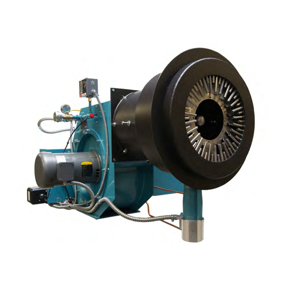
- Page 1 Webster Combustion Technology 619 Industrial Road, Winfield, KS 67156 Operation, Maintenance & Installation Manual Model JBE(X) Forced Draft Burners High Swirl Combustion Head Manual Part No. 950107 www.webster-engineering.com July, 2017 2017 All Rights Reserved...
-
Page 2: Safety Precautions
SAFETY PRECAUTIONS Good safety practices must be used when working on burner equipment. The potential energy in the electrical supply, fuel and related equipment must be handled with extreme care to prevent equipment failures, injuries and potential death. Throughout this manual, the following symbols are used to identify potential problems. WARNING This indicates a potentially hazardous situation, which if not avoided, could result in personal injury or death. -
Page 3: Table Of Contents
Table of Contents A. General Page 4 G. Maintenance Page 49 Nameplate Information ......Page 4 General ............ Page 49 Ratings ..........Page 4 Physical Inspection ........Page 49 Product Offering ........Page 6 Fuel-Air-Ratio .......... Page 49 Your Complete Manual ......Page 6 Gas Fuel Systems ........ -
Page 4: General
This manual covers the Models JBE and JBEX burners used as the controlling document. offered by Webster Combustion Technology LLC. These burners are intended for commercial and industrial NOTE: This manual must be readily available to all applications. - Page 5 MODEL JBE(X) BURNER MODEL CONFIGURATION FIGURE A-2 JBEX5G - 75 K - RM7800L - M.25 - M - MA - UL/CSD-1 BURNER SERIES CODES AND LISTINGS No FGR JBEX With FGR HOUSING SIZE CSD-1 5, 7, 9 FUELS NFPA-85 OIL SYSTEMS Gas / Oil Pressure Atomizing Modulation By-Pass...
-
Page 6: Product Offering
5. Service, Parts and Other Information FGR is closed during oil firing). Service and parts are available from your local Webster Representative. For a list of Webster 4. Your Complete Manual Representatives, please visit the Webster website at: In addition to this manual, there are several other www.webster-engineering.com or call 620-221-7464. - Page 7 Figure A-3 - General Ratings Nat. Gas or Propane #2 Fuel Oil Min. Firing Rate Max. Firing Rate Min. Firing Rate Max. Firing Rate (MBH) (MBH) (GPH) (GPH) Model Standard w/FGR Standard w/FGR Standard w/FGR Standard w/FGR JBE(X)5*-50J 1,240 1,030 14,900 12,370 JBE(X)5*-75J...
-
Page 8: Components
B. Components 1. General 5. Oil Fuel Components 2. Combustion Air 6. Flue Gas Recirculation (FGR) 3. Burner Drawer 7. Fuel-Air-Ratio Controls 4. Gas Fuel Components 8. Electrical Controls Burner Diffuser Access Mounting Flange Adjustment Bolt Cover Atomizing Air Pressure Switch Gas Spuds Oil Nozzle Combustion... -
Page 9: General
On - Off Switch Transformer Power Failure Fuses Manual Reset Motor Starter Alarm Silencing Switch (Optional) Controller Reset Call for Heat Light Power On Light Gas On Light Alarm Light Alarm Buzzer Control Relays Terminal Strip Flame Safeguard Figure B-6 Control Panel (Gas Shown) 1. -
Page 10: Burner Drawer
system (linkage), the damper shaft is connected by linkage to the jackshaft. On a parallel positioning system (linkageless), the shaft is directly coupled to the actuator for the air damper. The air damper mounts to the fan inlet and controls the air flow to the fan. -
Page 11: Gas Fuel Components
Scanner above this level, it will trip the switch and cause the burner The scanner is mounted to a sight tube that extends to shut down. past the face of the diffuser (approximately 1/8“) Low Gas Pressure Switch where it can detect the pilot or main flame. This This switch is located before the first shutoff valve. -
Page 12: Oil Fuel Components
attach the burner to the vessel. A fiberglass rope gasket Oil Supply Pressure Gauge (3/8” dia) is used to seal the mounting flange to the This indicates the oil supply pressure from the pump. refractory front plate. The rope is wrapped around the flange several times to seal the full diameter of the flange. -
Page 13: Flue Gas Recirculation (Fgr)
Oil Nozzle Nozzle Oil Pressure Gauge Several different types of oil nozzles may be used This gauge indicates the oil pressure at the oil nozzle. depending on the type of oil system, burner size, This reading is important in determining proper operation turndown and application. -
Page 14: Fuel-Air-Ratio Controls
FGR Adapter provide the basic fuel-air-ratio control required for good The FGR adapter provides an interconnection between combustion, however they can provide different features the housing and air damper, placed in the air flow stream and setup capabilities. to introduce the FGR. This location allows the FGR to Modulating Control be “induced”... -
Page 15: Electrical Controls
Multiple Setting Modulating Motor 8. Electrical Controls In some burner configurations, there are different ideal Control Panel settings for oil and gas firing, especially when higher The control panel (Figure B-6) contains the flame turndown is desired. This can be accommodated with an safeguard control, relays, terminal strips for electrical optional modulating motor that has different low fire and connections and other components required for unit... - Page 16 Junction Box The junction box contains the electrical connections that are required between the burner and control panel. Manual Potentiometer Rate Control The manual potentiometer is used to position the firing rate when the burner “Auto-Manual” switch is in “Manual” mode.
-
Page 17: Installation
Installer must clearly identify the main electrical power Webster recommends two air sources be provided, disconnect and the manual shutoff valve on the gas one located high, one low. Each air source must supply drop line to the burner. - Page 18 JBE(X) Manual Page 18 Section C - Installation...
- Page 19 JBE(X) Manual Page 19 Section C - Installation...
- Page 20 This surface must be sealed against the vessel. Fill voids Check vessel mounting between front requirements. plate and vessel with ceramic blanket 4” deep or as defined by Tighten clamp bolts vessel uniformly - check after manufacturer. firing for several hours. Entire O.D.
- Page 21 Gate Valve Oil Pump #1 Gate Valve Check Valve Burner #1 Boiler #1 Oil Valve Pressure Check Regulator Valve Oil Supply (By Others) Oil Return (By Others) Gate Valve Gate Valve Oil Pump #2 Check Gate Valve Boiler Boiler Valve Pressure Gauge Vacuum Check Valve...
-
Page 22: Refractory Frontplate
(provided with the burner if train is supplied High temperature fiberglass rope gaskets are used to by Webster), along with a detailed list of components for seal each connection. specific details. This must be followed to properly locate the components in the gas train. -
Page 23: General Oil Piping
This strainer is not part of the standard The oil piping must be constructed to provide the flow equipment supplied by Webster, but is intended to be and maintain the pressure required for proper system supplied and installed by others. The strainer should operation. -
Page 24: Pressure Atomized Oil System
9. FGR Duct System CAUTION If the burner is equipped with Induced Flue Gas Recircu- PUMP FAILURES CAUSED BY FOREIGN MATTER lation (IFGR), it will require a duct connection between IN THE OIL LINES WILL NOT BE COVERED BY the stack outlet of the boiler and the air inlet of the burner WARRANTY (See Figure C-13). - Page 25 For example, consider the arrangement shown in Figure FIGURE C-12 Pressure Drop per 100 ft of Duct (in. wc) C-13. There will be three standard 90 degree elbows and Max Inlet 22 feet of straight pipe. If 8” pipe is used, then the total 4”...
-
Page 26: Draft And Stacks
and into the fan. In cases of heavy condensation, a i. The FGR duct is normally made from schedule 40 condensate drip leg may be required on the bottom of pipe because it is obtainable and inexpensive. the housing, to remove condensate. Schedule 20 pipe can also be used. -
Page 27: Electrical System
resonance. The size should be based on a maximum The remote control panel must be securely attached to velocity of 30 ft/sec. Changes in direction must be as either the floor or the wall. This should include lag bolts. slow as possible. Circular elbows should be of at least a The wiring diagram for the specific job should be four piece construction with a centerline radius that is at followed for connections to the panels and external... -
Page 28: Fuel And Control Systems
D. Fuel and Control Systems Gas Systems Electrical Controls Gas Pilot Operating and Modulating Controls Pressure Atomized Oil Flame Safeguards Air Atomized #2 Oil Fuel-Air-Ratio Controls for the unit must be included in the study. The burner can be equipped with a wide variety of fuel and operating systems to control the fuel, air, modulation and 1. - Page 29 722005 Field Piped Pilot Gas Pressure Pilot Solenoid Pilot Manual Regulator Valve Ball Valve Gas Pilot Ignitor Vent To Outside Main Motorized Man Reset High Vent Atmosphere Man Reset Low Gas Valve Gas Pressure Gas Pressure Switch W/POC Test Switch 26 Sec.
-
Page 30: Gas Pilot
A vent valve is provided in some applications to allow gas bustion is to adjust the regulator to get rated capacity. that may leak past the first valve to escape to a safe point This regulator is usually at the beginning of the train, but of discharge. - Page 31 Optional Low Oil Pressure Switch Pressure Gauge Solenoid Solenoid Valve Valve Oil Nozzle (Bypassing) Typical Field Supplied Items - By Others Shutoff Valve Strainer Suction Supply Oil Pump Line Pressure Modulating Gauge Relief Valve Check Oil Metering Check Valve Valve Return to Tank Valve (No Manual...
-
Page 32: Air Atomized #2 Oil
The oil pump is supplied as a separate assembly that turndown rates, the bleed valve is set manually and does includes the pump, backpressure regulator, motor, not vary. In other systems with higher turndowns, the coupling, interconnecting housing and motor (FigureB-13). bleed valve is modulated with firing rate, by connection to An optional gauge may also be provided. -
Page 33: Operating And Modulating Controls
manufacturer. In all cases, these controls must be drops below the “Burner On” point (“B” on Figure D-8) integrated together. and initiates the shut down sequence when the load is satisfied and the temperature or pressure rises above 7. Operating and Modulating Control the “Burner Off”... -
Page 34: Preliminary Adjustments
E. PRELIMINARY ADJUSTMENTS 1. Visual Inspection 1. Visual Inspection 2. Burner drawer checkout 3. Motor Rotation The shipment and installation of the burner can result in 4. Fuel, FGR and Air Control loose connections, bent arms and other changes. The 5. -
Page 35: Motor Rotation
GAS SPUDS FLAME SCANNER MOUNTING FLANGE BURNER DRAWER DIFFUSER OIL NOZZLE PILOT GAS LINE CONNECTION BLOWER HOUSING Figure E-1 Burner Drawer Setup The burner is adjusted at the factory with initial settings for • The word “TOP” should appear on the top of the oil this application. - Page 36 Honeywell Brand Modulation Motor: Figure E-3 shows the internal settings of the multiposition The modulating motor can be operated by removing the modulation motor. Each adjustable cam setting is related cover, and removing the yellow wire to drive the motor to to an electrical connection (or circuit in motor).
-
Page 37: Fuel Cam Adjustments
RAW GAS ORIFICE ACCESS PLUG RAW GAS TUBE GAS SUPPLY 1/16” VENTURI AIR ADJUSTMENT 30° 1/16” ELECTRODE & INSULATOR ASSY Figure E-5 Gas Pilot On combination fuel, linkage burners with FGR, the shutoff d. The adjusting screws should form a smooth contour FGR valve may require adjustment for oil firing. -
Page 38: Pilot And Scanner Set Up
Turndown and low fire air requirements will dictate actual position. A high turndown burner will have a very small Removable gap at low fire (1/16”) while a normal turndown could have gaps of 1/8” to 1/4”. High fire position is typically 30 open, depending on the application. -
Page 39: Air Proving Switch
11. Operating and Modulating Controls need picture of Low Oil Tem- The operating controls will not be used during the perature switch burner setup, except that the high limit and operating controls can cycle the burner off and should be set for the highest allowable pressure for the application. -
Page 40: Startup And Operating Adjustments
This section covers the startup and operating adjustments at high rates for extended periods of time and the load of the Webster Model JBE(X) burner. must be capable of using this energy. ______A combustion analyzer with O2 and CO (for gas) WARNING must be available to tune combustion. -
Page 41: Fuel Cam Adjustments
flexible strip is required to move to a screw position where it is initially not in contact with the screw. Also, Fire the movement from one screw to the next cannot be Drive Arm too large (more then 1/8”). This will cause the strip to flex and will lead to premature failure of the strip. -
Page 42: Burner Drawer Adjustments
Burners equipped with Posi-Control can be adjusted for • Mark the distance of the oil gun tube from the drawer. individual air and FGR settings on both fuels and can easily • Mark the distance of the scanner to the drawer handle these variations, even with lower NOx levels. -
Page 43: Single Fuel Setups
6. Single Fuel Setups the multipoint modulating damper motor is adjusted to bring the low fire air setting to match the oil needs. Single fuel burners can be adjusted following the pro- cedures in Section 9 for gas firing, Section 10 for pressure There are several different options available that can atomized oil and Section 11 for air atomized #2 oil. - Page 44 move from closed to a low flow position after proving about 10% below any guaranteed NOx performance. main flame. A balance of the FGR control valve and air damper are NOTE: If the burner is not operating as indicated, follow required to obtain the final result, as each can impact the troubleshooting guide steps to determine the problem the other.
-
Page 45: Pressure Atomized Oil Setup
Natural Gas Natural Gas With FGR No FGR % Rate Figure F-2 % O2 % O2 O2 levels 10.0 WARNING 10. Pressure Atomized Oil Setup DO NOT ATTEMPT TO START THE BURNER WHEN EXCESS OIL HAS ACCUMULATED, WHEN THE UNIT IS FULL OF VAPOR, OR The pressure atomized oil system has a limited range of WHEN THE COMBUSTION CHAMBER IS HOT. -
Page 46: Air Atomized #2 Oil Setup
p. Adjust the low fire input, using the fuel cam and air WARNING damper adjustments. If the burner is equipped with FGR, DO NOT ATTEMPT TO START THE BURNER WHEN EX- adjust the NOx level according to the type of system (limit- CESS OIL HAS ACCUMULATED, WHEN THE UNIT IS FULL ing potentiometer or matching gas). -
Page 47: Operating Control Adjustments
according to the type of system (limiting potentiometer or safe shutdown. matching gas). The limit switches would include the air proving switch r. Re-adjust the midfire points for the correct O2 levels. on the burner. Limits for gas operation could include the The linkage may need to be readjusted to obtain the correct high and low gas pressure switches and for oil firing, the relationship between the fuel valve and air damper. -
Page 48: Burner Shutdown
c. If the flame signal does not drop out as required, check the location of the pilot and scanner, as shown in Figure E-1. This may also indicate a faulty scanner or amplifier. 15. Burner Shutdown Normal operation of the burner will allow the operating con- trols to shut the burner down when the load demand is sat- isfied. -
Page 49: Maintenance
(over 10”) is a good indication that the strainer 3. Fuel-Air-Ratio Controls needs to be cleaned. Strainers provided by Webster will use a wire mesh basket inside a canister. After turning The fuel-air-ratio controls must be maintained in good op- the pump off (and making sure there is no pressure on erating condition. -
Page 50: Fgr Systems
ket. The canister does not need to be drained. Be care- Other checks: ful with the gasket when removing or replacing the cover a. The condensation traps must work properly and be in- to insure a good seal. The basket can be lifted out and stalled to capture all of the condensation. -
Page 51: Inspection And Maintenance Schedule
8 - Inspection and Maintenance Schedule Frequency Performed By Component / Item Recommended Action or Test Burner Flame Visual inspection of burner flame. Jackshaft and Linkage Visual inspection for smooth and free travel. Air Damper Visual inspection for smooth and free travel. Fuel Metering Valves Visual inspection for smooth and free travel. -
Page 52: Combustion Chart
9 - Combustion Chart This graph shows the relationship between excess air, %Oxygen and %CO2, which is typically obtained from a flue gas analyzer. The values are based on a dry reading, where the flue gas is extracted and cooled before the analysis if done. - Page 53 H. Troubleshooting System Cause Correction No Ignition Electrode is grounded. Porcelain is cracked. Replace (lack of spark) Improperly positioned electrode Recheck dimensions Loose ignition wire connection Reconnect or tighten Defective ignition transformer Check transformer, replace No Ignition Lack of fuel, no gas pressure, closed fuel valve Check fuel supply and valves (spark, no flame) No voltage to pilot solenoid...
- Page 54 System Cause Correction High CO at low fire (con’t) High stack draft (especially at low fire) Stabilize draft (firing gas) Poor air flow distribution (off center flame) Adjust air straightener blade Diffuser not in optimum position Adjust diffuser position in or out Fluxuating gas pressure (regulator not holding pressure) Check regulator pressure, sensing line and supply pressure: sized properly...
- Page 55 System Cause Correction Cannot obtain rated input on Oil pressure too low Increase oil pressure oil firing (pres. atom.) (con’t) Flow valve set too low (should be closed at high fire) Adjust oil control valve Oil flow valve set too low (should be closed at high fire) Adjust oil control valve Cannot obtain rated input on Oil nozzles plugged...
- Page 56 Webster Combustion Technology LLC 619 Industrial Road Winfield, KS 67156 Ph: 620-221-7464 Fax: 620-221-9447 e-mail: service@webster-engineering.com www.webster-engineering.com...
Need help?
Do you have a question about the JBE Series and is the answer not in the manual?
Questions and answers