Table of Contents
Advertisement
Quick Links
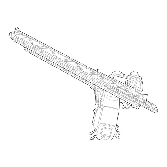
SEH - ED 24/27/28/30/32/33 metres
- In order that the AXIALE II suspension provides you with complete satisfaction:
- running in is needed, and this takes place in the first few hours of operation,
- it is highly recommended that you grease moving and frictional parts before each use.
- Choose correct advance speed for your field, and do not make rapid or ill-considered changes of direction:
this prolongs service life.
- Regularly check nozzles and lines because these can become blocked or worn; check flow rate.
- To ensure correct attachment and operation of spray boom, follow all the fitting and operation advice in this
manual.
Wiring diagrams: see Agent manuals
82.486 "AXIALE II" Booms
"AXIALE II" BOOMS
82.486-A
IMPORTANT ADVICES
ENGLISH
©
BERTHOUD Agricole 02/2008
1
Advertisement
Table of Contents

Subscribe to Our Youtube Channel
Related Manuals for Berthoud AXIALE II SEH Series

Summary of Contents for Berthoud AXIALE II SEH Series
- Page 1 SEH - ED 24/27/28/30/32/33 metres 82.486-A ENGLISH © BERTHOUD Agricole 02/2008 IMPORTANT ADVICES - In order that the AXIALE II suspension provides you with complete satisfaction: - running in is needed, and this takes place in the first few hours of operation, - it is highly recommended that you grease moving and frictional parts before each use.
-
Page 2: Table Of Contents
summary See pages - Technical specifications ..............- "AXIALE" suspension ................ - Boom arm section dimensions ............- Layout of spraying sections .............. - Adjustment of the arms ..............- Locking of a boom with an hydraulic lock ......... 10 - Locking of a boom with a mechanical lock ........ -
Page 3: Technical Specifications
TECHNICAL SPECIFICATIONS - Suspension "autostable pendular" type. - Boom frame mounted on parallelogram. - Anti-whip structure based on trianguled concept. - Steel structure protected by surface treatment, and polyester paint heat treated in furnace. - Indicators for height, angle correction and geometry. - All hydraulic functions controlled by electro-hydraulic spool valves or electro-hydraulic selector. -
Page 4: Boom Arm Section Dimensions
BOOM ARM SECTION DIMENSIONS (frame) 24 m 28 m 30 m 32 m 33 m 12 m 14 m 17 m 17 m 17 m 18 m 21 m 23.5 m 24.5 m 25 m 82.486 "AXIALE II" Booms... -
Page 5: Layout Of Spraying Sections
LAYOUT OF SPRAYING SECTIONS Boom Number of Number of nozzles per section width sections Breakdown of the 20 m frame (in terms of nozzles ½ m) = 4 - 4 - 10 - 4 - 10 - 4 - 4 20 m 10 - 10 - 10 - 10 20 m... -
Page 6: Adjustment Of The Arms
ADJUSTMENT OF THE ARMS ADJUSTMENT OF THE BOOM - Your boom is equipped with a device which adjusts arm alignment in working position and adjustment for the transport position. ADJUSTMENT OF THE MAIN ARMS IN TRANSPORT POSITION (figure 1) Arms closed in transport position (they must be fully against the arm supports). - Remove the pin (5) (figure 1) then actuate the unfolding actuators (1) in open position (end of travel). - Page 7 Detail of the ball joint 82.486 "AXIALE II" Booms...
- Page 8 ADJUSTMENT OF THE ARMS (continuation) ADJUSTMENT OF THE INTERMEDIATE ARMS (figure 5) - Adjustment of the intermediate arm (2) in relation to the main arm (1). - Place the arms in open position. IN THE VERTICAL PLANE: - Turn nuts (3) for vertical adjustment. IN THE HORIZONTAL PLANE: - Turn nut (4) and bolt (5) for horizontal adjustment.
- Page 9 82.486 "AXIALE II" Booms...
-
Page 10: Locking Of A Boom With An Hydraulic Lock
LOCKING OF A BOOM WITH AN HYDRAULIC LOCK (figure 7) - Before making any adjustments, make sure that the central part is in horizontal position. To adjust the lock, extend the actuator rods (1), loosen the locknuts (2), end tips (3) fully against the oscillating frame then retighten the locknuts (2). - Page 11 82.486 "AXIALE II" Booms...
-
Page 12: Adjustment Of Lowering And Suspension Of The Boom
ADJUSTMENT OF LOWERING AND SUSPENSION OF THE BOOM (figure 10) - The limiter (1), located below the hydraulic units, is used to set the boom's lowering speed. - Nitrogen cylinders mounted on the raising cylinders are used for vertical damping of the boom. (The more open the limiter, the more brutal the shocks. - Page 13 82.486 "AXIALE II" Booms...
-
Page 14: Slope Correction Cylinder Speed Adjustment
SLOPE CORRECTION CYLINDER SPEED ADJUSTMENT (figure 13) - The limiter (1), located on the slope correction cylinder is used to adjust its speed. - Procedure: - Unscrew the hex-socket cap screw (2) situated in the flow limiter's adjusting wheel (3). - Adapt the flow limiter's setting. - Page 15 82.486 "AXIALE II" Booms...
-
Page 16: Advice On Boom Maintenance
(Paint used: BERTHOUD 769.077 blue aerosol). - Recommendations for lubrification: TOTAL FINA ELF : LICAL EP 2 Lubrication of the central axis: KLUBER 46 MR 401 grease, BERTHOUD reference 786.703 USER SAFETY - When handling crop treatment products use appropriate safety clothing. -
Page 17: Electrical Control Box Of The "Axiale Ii" Ed Boom With Hydraulic Lock
ELECTRICAL CONTROL BOX of the "AXIALE II" ED BOOM with HYDRAULIC LOCK (figure 16) UNFOLDING ARMS FOLDING ARMS 1 - POWER UP THE CONTROL BOX 1 - LOCKING THE BOOM (before any other operation) Raise switch (1), the red lamp (a) lights. Raise switch (2) and hold it, locking occurs as soon as the red lamp (b) lights. -
Page 18: Electrical Control Box Of The "Axiale Ii" Ed Boom With Mechanical Lock
ELECTRICAL CONTROL BOX of the "AXIALE II" ED BOOM with MECHANICAL LOCK (figure 16) UNFOLDING ARMS FOLDING ARMS 1 - POWER UP THE CONTROL BOX 1 - RAISING THE BOOM (before any other operation) Raise switch (1), the lamp (a) lights. Raise and hold switch (3) until the maximum position is reached. -
Page 19: Axiale Ii" Ed Boom Options
"AXIALE II" ED OPTION IMPORTANT : For road operation, the angling drawbar or tracker must be blocked (pin G, figure 17). For field work, remove the pin (G). ANGLING DRAWBAR OPTION: (1 switch) - Push switch to the right or left to move the drawbar. ANGLING DRAWBAR OPTION WITH RESET: (1 switch + 1 push-button) - Push switch to the right or left to move the drawbar. -
Page 20: Electrical Control Box Of The "Axiale Ii" Seh Boom With Mechanical Lock
ELECTRICAL CONTROL BOX of the "AXIALE II" SEH BOOM with MECHANICAL LOCK (figure 18) UNFOLDING ARMS FOLDING ARMS 1 - POWER UP THE CONTROL BOX 1 - RAISE THE BOOM Raise switch (1), the lamp (a) lights. Without tracking drawbar option: Actuate the handle of the tractor's double effect 2 - CLEARANCE OF THE BOOM FROM ITS hydraulic distributor to lift the boom. - Page 21 Electrical control box 290 x 271 mm Electrical control box 365 x 244 mm Electrical control box 297 x 214 mm 82.486 "AXIALE II" Booms...
- Page 22 THOUD agricole Z.I. de Bois Baron - 1, rue de l’Industrie 69220 BELLEVILLE S/S - FRANCE Phone: 33 (0)4 74 06 50 50 - Fax: 33 (0)4 74 06 50 77 Internet: www.berthoud.com - E-mail: berthoud-agricole@berthoud.com 82.486 "AXIALE II" Booms...
Need help?
Do you have a question about the AXIALE II SEH Series and is the answer not in the manual?
Questions and answers