Table of Contents
Advertisement
Advertisement
Table of Contents

Related Manuals for Amber M32

Summary of Contents for Amber M32
- Page 1 M32 FLYWHEEL INSTALLATION & MAINTENANCE MANUAL v2.0 March, 2018...
- Page 2 While every precaution has been taken in the preparation of this document, it may contain technical inaccuracies, omissions, and typographical errors, and Amber Kinetics, Inc. is under no obligation to update or otherwise correct this information. Amber Kinetics, Inc. makes no representations or warranties with...
-
Page 3: Table Of Contents
3.3 - Site Preparation ............18 3.4 - Capsule Placement ..........19 3.5 - M32 Flywheel Preparation ........20 3.6 - M32 Flywheel Placement ........23 3.7 - Electrical Connections ......... 25 3.8 - Completing the Installation ........ 29 Copyright 2018 by Amber Kinetics. All rights reserved. - Page 4 This page intentionally left blank. Copyright 2018 by Amber Kinetics. All rights reserved. M32 FLYWHEEL - INSTALLATION & MAINTENANCE MANUAL...
-
Page 5: Introduction
• About This Manual: Layout and organization of this Installation Manual. • About Amber Kinetics: Company information. • Features and Benefits: Why the M32 flywheel compares well to batteries. • Description: Key components of the M32 flywheel. • Theory of Operation: How the M32 flywheel stores and discharges energy. -
Page 6: About This Manual
[ESC]. If more than one key should be pressed simultaneously, the notation will appear as [KEY1]+[KEY 2], for example [ALT]+[F4]. Copyright 2018 by Amber Kinetics. All rights reserved. M32 FLYWHEEL - INSTALLATION & MAINTENANCE MANUAL... -
Page 7: Organization
1.1.2 - Organization This manual contains the following chapters: 1 - Introduction: Introduces the M32 flywheel by describing its key features, components, operation, specifications, and safety features. 2 - Safety: Provides important safety information that must be followed when installing, commissioning, operating, and maintaining the M32 flywheel. -
Page 8: About Amber Kinetics
The M32 flywheel by Amber Kinetics is the world’s first cost-effective energy storage system that safely and 1.2.1 - Support Policy reliably provides up to four hours of continuous power... - Page 9 The M32 flywheel offers the following key benefits over traditional chemical batteries: • >86% round trip efficiency (DC), includes self-discharge • No daily cycling limitations • No degradation over time • No HVAC required °F to • Operates in hot and cold environments (-40 122°F;...
-
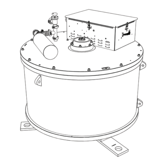
Page 10: M32 Flywheel Description
The rotor group operates in a vacuum to minimize rotational losses during storage. The M32 flywheel and Capsule are installed in an excavated hole in the ground, and a protective Capsule Lid is then placed on top of the Capsule to protect the M32 flywheel and electronics from rain and debris. - Page 11 Flywheel Housing • Capsule (not shown): Encloses the M32 flywheel (1). and other components within the excavated hole. • Bearing Caps (3): Cover and provide access to the upper and lower Bearings (4).
-
Page 12: Theory Of Operation
1.4 - Theory of Operation The M32 flywheel stores kinetic energy in a massive Multiple M32 flywheels can be connected in parallel to rotating disk. The amount of energy stored is defined meet desired power and energy requirements. The by the equation E=½Jω... -
Page 13: Specifications & Performance
1.5 - Specifications & Performance These tables provide basic mechanical, environmental, Electrical and electrical specifications for the M32 flywheel. Maximum power 8 kW (minimum) Mechanical Energy 32 kWh Weight 10,500lbs Full-power response <1 second (4,763kg) time Size (height/diameter) 52”x54” Discharge duration... -
Page 14: Safety Features
• Operation: Each M32 flywheel is manufacturing process that yields monitored 24/7/365 by a health the cleanest, highest-grade steel monitoring system. available. Copyright 2018 by Amber Kinetics. All rights reserved. M32 FLYWHEEL - INSTALLATION & MAINTENANCE MANUAL... -
Page 15: Safety
The order in which these guidelines appears is not intended to express or imply any priority or relative importance. Copyright 2018 by Amber Kinetics. All rights reserved. - Page 16 • This manual is an integral part of the M32 flywheel WARNING: THIS MANUAL IS FOR USE product. It contains important instructions that BY QUALIFIED PERSONNEL ONLY. must be followed when installing, commissioning, QUALIFIED PERSONNEL ARE THOSE and maintaining the M32 flywheel. Read this entire...
- Page 17 • All wiring and connections may have hazardous voltages and currents at any time. Only qualified • The M32 flywheel can continue to spin for up to 15 and authorized personnel may install and/or days following removal of DC power. Contact...
- Page 18 This page intentionally left blank. Copyright 2018 by Amber Kinetics. All rights reserved. M32 FLYWHEEL - INSTALLATION & MAINTENANCE MANUAL...
-
Page 19: Installation
This chapter describes the installation procedure for the M32 flywheel. This process begins with planning the installation, gathering the needed equipment and tools, and then preparing the site. Next, the M32 flywheel is installed in the ground and electrical connections are made. Finally, a vacuum pump is connected to the M32 flywheel(s) to ensure a proper level of vacuum inside the Flywheel Housing, and the site-wide wiring is completed. -
Page 20: Planning
3.1 - Planning When planning a multi-M32 flywheel installation: • Each block of M32 flywheels consists of two rows. • The total DC capacity will be 8kw times the number • Figure 3 displays the minimum clearance of M32 flywheels in the installation. -
Page 21: Equipment & Tools
M32 flywheel and Capsule during installation. • #2 Phillips screwdriver. • Shovels and/or other handheld earthmoving tools, • Vacuum vent tool. as appropriate for the installation site. • 1/8” hex driver. Copyright 2018 by Amber Kinetics. All rights reserved. 3 - INSTALLATION... -
Page 22: Site Preparation
3.3 - Site Preparation To prepare the site: • The bottom of the hole must be: • The Capsule that contains the M32 flywheel is Smooth enough to provide even support across approximately 82” (~208cm) tall and 70” (~178cm) the entire base of the Capsule. -
Page 23: Capsule Placement
Capsule, then clean out the Capsule as thoroughly as possible. Figure 4: Augered installation hole WARNING: REMAIN WELL CLEAR OF THE CAPSULE WHILE THE HOIST IS IN PROGRESS. Figure 5: Backfilling around the Capsule Copyright 2018 by Amber Kinetics. All rights reserved. 3 - INSTALLATION... -
Page 24: M32 Flywheel Preparation
FLYWHEEL IS PROPERLY SUPPORTED the Flywheel Rotor off of its shipping support posts. If TO PREVENT A FALL OR OTHER the M32 flywheel is being installed for the first time, UNEXPECTED MOVEMENT. then the jack screw will need to be adjusted using the procedure described in this section. - Page 25 3. Remove the six (6) bolts securing the lower 5. Loosen the locknut (A) securing the jack screw (B) Bearing Cap using a 3/8” (9.5mm) Allen wrench. to the M32 flywheel using the 1.5” (~39mm) open- ended wrench. Figure 8: Bolts securing the lower Bearing Cap Figure 9: Locknut (A) and jack screw (B) 4.
- Page 26 16. Turn off the Handheld Load Cell Reader, and then disconnect it from the DB9 connector. Connect the cable from the Electronics Enclosure to the DB9 connector. Copyright 2018 by Amber Kinetics. All rights reserved. M32 FLYWHEEL - INSTALLATION & MAINTENANCE MANUAL...
-
Page 27: M32 Flywheel Placement
3.6 - M32 Flywheel Placement To place the M32 flywheel inside the Capsule: 2. Slowly lower the M32 flywheel into the Capsule, using the tagline(s) and/or magnetic 1. Connect the three lifting straps and shackles to the manipulator(s) to align it such that the three feet M32 flywheel lifting points, as shown in Figure 12. - Page 28 Note: Your vacuum valve configuration on your M32 flywheel may vary from that shown in Figure 15. Figure 14: Securing the M32 flywheel in the Capsule 5. Close the vacuum valve, remove the vacuum relief tool, and then connect a vacuum pump to the 6.
-
Page 29: Electrical Connections
The specific conduit type 1. Run the following conduits and wiring to the M32 and routing (such as above- or below- flywheel and secure them to the Electronics grade) is beyond the scope of this Enclosure using watertight connectors: manual. - Page 30 5. Lower the upper electronics tray back into DC wires to the terminals on the lower electronics position, and then reinstall all fasteners. tray. Copyright 2018 by Amber Kinetics. All rights reserved. M32 FLYWHEEL - INSTALLATION & MAINTENANCE MANUAL...
- Page 31 Bare or green wire from the ground (G) terminal to the grounding lug on the Electronics Enclosure. Figure 20: Debug Cat6a Ethernet connection Figure 19: AC connections (upper tray) Copyright 2018 by Amber Kinetics. All rights reserved. 3 - INSTALLATION...
- Page 32 8. Connect the flywheel communications Cat6a 9. Connect the M32 flywheel(s) to the following Ethernet cable to the pigtail Ethernet cable coming components, and complete all external connections from the controller daughter card. Use the to those components: provided cable tie points to provide strain relief for Grid-tie inverter the cable (cable ties not shown).
-
Page 33: Completing The Installation
3. Connect a lifting strap and shackle to the lifting point at the top of the Capsule Lid. Connect the 1. Visually inspect the M32 flywheel and Capsule to other end of the strap to the crane or forklift, and... -
Page 34: Copyright 2018 By Amber Kinetics. All Rights Reserved
This page intentionally left blank. Copyright 2018 by Amber Kinetics. All rights reserved. M32 FLYWHEEL - INSTALLATION & MAINTENANCE MANUAL... -
Page 35: Testing And Commissioning
4 - Testing and Commissioning This chapter describes the pre-commissioning and spin-up procedures for the M32 flywheel. Copyright 2018 by Amber Kinetics. All rights reserved. -
Page 36: Pre-Commissioning Steps
Conduct a visual inspection of the installed M32 flywheel(s), paying particular attention to the following: • Each M32 flywheel is properly secured to its Capsule. • All electrical and communications connections to the M32 flywheel(s) have been completed in accordance with the instructions in this manual. -
Page 37: M32 Flywheel Spin-Up
4.2 - M32 Flywheel Spin-up The M32 flywheel spin-up process consists of the 5. Startup. following steps. Some or all of these steps may be a. Open Loop (~0 - 0.7 Hz). automated, depending on the specifics of the site b. - Page 38 This page intentionally left blank. Copyright 2018 by Amber Kinetics. All rights reserved. M32 FLYWHEEL - INSTALLATION & MAINTENANCE MANUAL...
-
Page 39: Maintenance
5 - Maintenance This chapter describes the regular maintenance required to keep the M32 flywheel in optimal operating condition. Copyright 2018 by Amber Kinetics. All rights reserved. - Page 40 Time Procedure At least once per quarter (every 90 days) Inspect the perimeter of the M32 flywheel cover for weeds, trash, and/or other debris that might be blocking the ventilation inlet, and remove if present. Every 10 years after initial installation...
- Page 41 This page intentionally left blank. Copyright 2018 by Amber Kinetics. All rights reserved. 5 - MAINTENANCE...
- Page 42 M32 FLYWHEEL INSTALLATION & MAINTENANCE MANUAL v2.0 March 2018 ©2018 Amber Kinetcs, Inc. All rights reserved.
Need help?
Do you have a question about the M32 and is the answer not in the manual?
Questions and answers