Table of Contents
Advertisement
Quick Links
Advertisement
Table of Contents

Related Manuals for NKT SUPERK EVO


Summary of Contents for NKT SUPERK EVO
- Page 1 SUPERK EVO White Light Laser PRODUCT GUIDE...
- Page 2 PRODUCT GUIDE This guide includes the following NKT Photonics Lasers: SuperK EVO Passively Cooled Supercontinuum White Light Laser in a Compact Form Factor SuperK EVO Air Cooled Supercontinuum White Light Laser with Regulated Cooling Fans SuperK EVO Water Cooled Supercontinuum White Light Laser with a Water Cooled Base SuperK EVO Product Guide Revision 1.02...
-
Page 3: Guide Overview
GUIDE OVERVIEW This product guide is intended to provide functional, operational and installation information for the SuperK EVO laser systems. The guide is divided into three sections: SuperK EVO Description – introduces the laser’s theory and functionality, its • interfaces, and chassis variants. - Page 4 Note: Highlights additional information related to the associated topic and/or pro- vides links or the name of the NKT guides describing the additional information. Caution: Alerts you to a potential hazard that could cause loss of data, or damage the system or equipment.
-
Page 5: Table Of Contents
Key Switch and Interlock Safety ..............20 Synchronizing External Equipment ..............21 Laser Accessory Management ................ 21 Status LEDs ........................ 23 Chassis Labels ......................24 2 Chassis Types ........................27 Passively Cooled SuperK EVO ................27 Air Cooled SuperK EVO ...................27 Water Cooled SuperK EVO ................... 28... - Page 6 Section 2 OPERATING THE LASER 3 Communicating with the Laser ..................33 CONTROL Software ....................33 Installing the software ..................33 Connecting the Laser to CONTROL ..............33 USB connection ....................33 Ethernet connection ................... 34 Grouping Connections ..................36 4 Turning on the Laser ....................... 39 Safety ...........................
- Page 7 Section 3 INSTALLING THE LASER 7 Mechanical Installation ....................65 General Installation .................... 65 Passively Cooled SuperK EVO ................ 65 Air Cooled SuperK EVO ..................65 Water Cooled SuperK EVO ................65 Installing the Passively Cooled Chassis ............. 66 Mounting Considerations ................. 66 Installing the Air Cooled Chassis .................
- Page 8 Appendices A Specifications ........................83 B Service and Support Information ................. 85 Servicing the Laser ....................85 Opening the laser chassis ................85 WARRANTY VOID IF REMOVED Label ............85 Support Contact Details ..................85 Support Email ....................... 85 Online Support Web-page ................85 Shipping Address ....................
-
Page 9: Tables
Table 4: Operating Modes ....................55 Table 5: Device Monitor Parameters................56 Table 6: External Control Input Parameters ..............59 Table 7: Passively Cooled SuperK EVO Installation Specifications ......66 Table 8: Air flow considerations ..................68 Table 9: Cooling Water Specifications................69 Table 10: External Bus Connection Mode ...............77... -
Page 11: Figures
Figure 4: SuperK EVO Status LEDs ................23 Figure 5: SuperK EVO Panels ..................25 Figure 6: Passively Cooled SuperK EVO - Heat Conduction Plate ......27 Figure 7: Air Cooled SuperK EVO ................... 28 Figure 8: Water Cooled SuperK EVO ................29 Figure 9: CONTROL Panel Navigation ................ - Page 12 Figure 36: Example Pulse Circuit ..................78 Figure 37: Pulse (NIM) Trigger Delay Control ............... 79 Figure 38: Varia connected to a SuperK EVO Laser ..........88 Figure 39: Select connected to a SuperK EVO ............89 Figure 40: Select AOTF example output - 640nm central wavelength ....90 Figure 41: SuperK LLTF Contrast connected to a SuperK EVO .......90...
-
Page 13: Procedures
PROCEDURES Connecting a PC to the laser using a USB cable............34 Connecting a PC to the laser using Ethernet............... 35 Grouping connections in a collection ................37 Turning on the Laser ......................40 Turning off the Laser ......................41 Relocating Panels........................ -
Page 15: Superk Evo Description
SECTION 1 SUPERK EVO DESCRIPTION This section provides a description of the laser and its chassis types. “Laser Description” on page 17 • “Chassis Types” on page 27 •... -
Page 17: Laser Description
Laser Description SuperK EVO lasers are a series of white light lasers (WLL) classified as a class 4 laser source which can generate a pulsed supercontinuum. Light frequencies from 400 to 2400 nm are emitted in a single spatially coherent beam with a pulse rate that is customizable according to application requirements. -
Page 18: Configuration And Operation Overview
Configuration and Operation Overview Figure 1 SuperK EVO Collimator Output Aperture 12 mm 3.5 mm Configuration and Operation Overview The laser is operated by using either NKTP’s CONTROL application on an external PC or your own custom application using NKTP’s available SDK. -
Page 19: Control Application
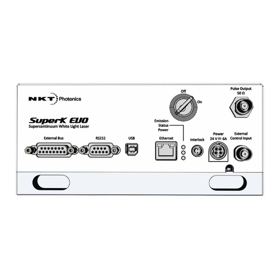
Configuration and Operation Overview Figure 2 SuperK EVO Front Panel Key Switch 6. RJ-45 Ethernet Connector Pulse Output (Oscillator) Interlock External Bus 8. DC Input RS-232 9 Pin dB Serial Connector 9. External Control Input Type B USB Serial Connector... -
Page 20: Advanced Laser Control
Warning: The Output Control feature must not be used as a safety interlock. Note: The feature is by request only, contact NKT Photonics. Key Switch and To enhance safety, the laser is equipped with an interlock interface and a keyed Interlock Safety switch. -
Page 21: Synchronizing External Equipment
External Equipment the output pulse train of the laser. The connector outputs a signal that is synchronized to the pulsed oscillator inside the SuperK EVO. The signal is NIM compliant (see standard DOE/ER-0457) and ranges from 0 to approximately -1 V. - Page 22 Configuration and Operation Overview Note: The External Bus will only prevent the laser from operating when the Inter- lock circuit is connected as required by safety regulations either local or mandat- Laser Description...
-
Page 23: Status Leds
Status LEDs Status LEDs The front panel houses three status LEDs as described in Table Figure 4 SuperK EVO Status LEDs Table 1 Status LEDs Condition Description Emission ON White The laser is ON and emitting high-power class 4 laser radiation through the collimator optic. -
Page 24: Chassis Labels
Chassis Labels Chassis Labels The SuperK EVO chassis includes multiple labels that indicate hazards and regulatory or manufacturing information. The labels are located on several panels, the armored fiber cable and the collimator as described in with Table 2 panels shown in... -
Page 25: Figure 5 Superk Evo Panels
Chassis Labels Figure 5 SuperK EVO Panels Left Rear Front Collimator Laser Description... - Page 26 Chassis Labels Laser Description...
-
Page 27: Chassis Types
“Mounting Considerations” on page 66). Air Cooled SuperK EVO The air cooled chassis of the SuperK EVO laser uses a fan plenum shelf with dual fans to thermally regulate the laser operation. Cool air drawn from each of the fan... -
Page 28: Water Cooled Superk Evo
Figure 7 Air Cooled SuperK EVO Air flow considerations An air-cooled SuperK EVO laser must be mounted so that gaps at the front and rear panel air outlets are sufficient to allow cool and hot air to circulate efficiently. The gap dimensions are listed in... -
Page 29: Figure 8 Water Cooled Superk Evo
Water Cooled SuperK EVO Figure 8 Water Cooled SuperK EVO Caution: Only use a coolant liquid with anti-corrosive properties suitable for use with aluminum tubing. Chassis Types... - Page 30 Water Cooled SuperK EVO Chassis Types...
-
Page 31: Operating The Laser
SECTION 2 OPERATING THE LASER This section describes how to manage and operate the laser and includes the chapters: “Communicating with the Laser” on page 33 • “Turning on the Laser” on page 39 • “CONTROL Interface” on page 43 •... -
Page 33: Communicating With The Laser
Communicating with the Laser The SuperK EVO laser can be managed using NKTP CONTROL software installed on a PC. This chapter focuses on how to obtain and install the CONTROL software and connect the PC using either Ethernet or USB connectivity. -
Page 34: Ethernet Connection
If necessary, wait for the Windows device manager to install the USB drivers for the connection. Launch the CONTROL software by either: clicking on Windows – Start – Programs – NKT Photonics –CONTROL – or – double clicking the CONTROL shortcut on the desktop The CONTROL window opens. - Page 35 Connecting the Laser to CONTROL subnets are used they must be accessible to each other. However, to configure the laser’s IPv4 address and port, you must first connect to it using a USB cable directly from a PC using CONTROL. Procedure 2 Connecting a PC to the laser using Ethernet Action Access the laser from your CONTROL PC using a USB cable as described in...
-
Page 36: Grouping Connections
Connecting the Laser to CONTROL Action Click the Save button to save the configuration of the new Ethernet connection. To delete or modify a configured port: Delete button Highlight the port and: Click the delete button - or - Edit button Click the edit button Click Save when finished. - Page 37 Connecting the Laser to CONTROL Procedure 3 Grouping connections in a collection Action Access the laser from your CONTROL PC using a USB cable as described in Connecting a PC to the laser using a USB cable on page From the Connect menu list select Config to open the Port Configuration window.
- Page 38 Connecting the Laser to CONTROL Action When you have added all connections to the collection, click “Save”. Open the Connect drop down menu and click on the collection. CONTROL will scan only the ports included in the collection. Collection Communicating with the Laser...
-
Page 39: Turning On The Laser
Do not turn on the laser if it has been exposed to temperature and hu- midity beyond the operating specifications. The SuperK EVO is designed to oper- ated in a non-condensing environment from +18 to +30°C. Before turning on the laser, allow it at least 30 minutes to reach room temperature. -
Page 40: Controlling The Laser Emissions
Controlling the Laser Emissions Controlling the Laser Emissions Turning On the Follow the steps in to turn on the laser. Table 4 Laser Procedure 4 Turning on the Laser Action On the front panel of the laser, turn the key switch on the laser’s front panel to the ON position. -
Page 41: Turning Off The Laser
Controlling the Laser Emissions Turning Off the Follow the steps in to turn off the emissions. Table 5 on page 41 Laser Procedure 5 Turning off the Laser Action Turn of the laser emissions by clicking on the software Emission button. The Emission button light turns from RED (ON) to green (OFF). - Page 42 Controlling the Laser Emissions Controlling the Laser Emissions...
-
Page 43: Control Interface
The control panel provides custom controls for CONTROL – Operating Mode the laser and accessories selected. For example, on page 55 the SuperK EVO provides configuration controls for power and trigger delay. Application This panel displays a debugging log that can be Application Log panel on saved to a file. -
Page 44: Relocating Panels
CONTROL Overview Relocating Panels The panels displayed by CONTROL can be dragged to any location within the main interface or into a separate floating panel. describes how to Procedure 6 move a panel: Procedure 6 Relocating Panels Action Left Click and hold the top title bar of the panel. While holding the left mouse button down drag the panel to another location in the main window. -
Page 45: Toggling Panels
CONTROL Overview Toggling Panels Use the Menu > Window drop down menu to check and uncheck panels to be viewed. Figure 12 Toggling panel visibility Check the panels to display them Note: You can also close any panel by clicking the X in the upper right corner of the panel. -
Page 46: Status Panel
Status Panel Status Panel The Status Panel provides status indicators, error messages, emission control function and a CONTROL settings menu. Figure 14 Status Panel Status Indicators The panel displays the following indicators: Interlock Indicates the status of the Interlock circuit and whether emissions can be turned on or not. -
Page 47: System Info
Status Panel ON RED – There is a fault, laser emissions are shutdown and cannot be • turned ON. A fault message will be displayed when this indicator turns ON RED: Fault Message Action Interlock opened while emission on a) Cycle the key switch to OFF and then ON b) Close the external interlock circuit Watchdog timeout Reconnect NKTP CONTROL and reset the interlock... -
Page 48: Control Settings
Status Panel CONTROL Settings The CONTROL settings are accessible by clicking the gear icon in the upper right corner of the Status panel. Clicking the gear icon displays a menu of setting items as shown in Figure Figure 15 CONTROL Settings Click the gear icon to access the menu Setting Item... -
Page 49: Figure 16 Watchdog
Status Panel Watchdog As an added safety feature, the watchdog will automatically turn off the laser emissions if communications with CONTROL are lost. The feature can be enabled or disabled and has an adjustable timeout. When communications are lost with the laser, the watchdog timer counts down from the timeout setting value (1 to 255 seconds). -
Page 50: Control Menu
CONTROL Menu Figure 18 View Check to display CONTROL Menu There are five drop down menus in the main control window as highlighted in 19. Click on the items in the menu to reveal the drop down menus. Figure Figure 19 Menu Items Menu Item Function File... -
Page 51: Log Downloader
The log files are stored in a local database on the CONTROL PC. However, certain NKTP modules, including the SuperK EVO main board do not support automatic download of log files. For these modules, you can use the Log Downloader tool to put the device into dedicated log download mode by enabling a collect log function. - Page 52 CONTROL Menu Procedure 8 Using the Log Downloader Action Open the Tools menu and click on Log Download to start the Log Downloader tool. The tool displays all connected modules with log capability. To decrease the download time of the module log files, CONTROL continuously collects module log data and stores this log data in a local database on the...
-
Page 53: Extensions Overview
This tool is used to view the installed extensions (plugins) that are included with Overview CONTROL. The extensions are found in the following folder: C:\Program Files (x86)\NKT Photonics\NKTP CONTROL\Plugins To view the extensions, open the Tools menu and click on Extensions Overview. The Extensions Overview window will be launched as shown in... - Page 54 The PubEVOLib.dll details highlighted in shows the version of the .dll Figure 20 file (1.1.2.303), the included extensions (SuperK EVO Extension) and which module types they support. Note: Multiple extensions for a wide range of NKTP lasers types are typically in- stalled when using the default installation of CONTROL.
-
Page 55: Control - Operating Mode
CONTROL – Operating Mode CONTROL – Operating Mode For SuperK EVO the control panel can be configured to present different operating mode controls. Control of the laser emissions varies according to the mode chosen. To select one of the modes listed in... -
Page 56: Device Monitor
Device Monitor Discovered Devices • Closed Communication Ports • The panel includes three buttons in the upper left corner. You can use the buttons to clear, save or print the log. Click on the cross in the upper right corner of the Application Log window to close the Application Log. - Page 57 Device Monitor Parameter Description FW Ver. The device module’s firmware release date. Module Serial The serial number of the device module PCB Serial The device module’s printed circuit board serial number PCB Ver, The version of the device module’s printed circuit board. Sp.
- Page 58 Device Monitor CONTROL Interface...
-
Page 59: Configuring External Control
Configuring External Control This chapter covers configuration details for: External Feedback – describes how to connect a feedback circuit to the • laser (see 19) to stabilize the output power level. Figure 2 on page External Enable – describes how to connect an external logic signal to the •... -
Page 60: External Enable
Warning: The laser emission is still ON when the booster is OFF, however residual laser emissions are still produced. Figure 23 External Enable Trigger vs Optical Output Rise TTL CMOS Trigger External Control Input SuperK EVO Detector Configuring External Control... -
Page 61: Configuring External Enable
External Enable Configuring To turn the laser output ON and OFF with an external logic signal, the laser must External Enable be in External power mode (digital). shows the Operating mode drop Figure 24 down menu, select External power mode (digital). Figure 24 Setting External power mode Note: If the External power mode (digital) is selected in the laser configuration and... - Page 62 External Enable Configuring External Control...
-
Page 63: Installing The Laser
SECTION 3 INSTALLING THE LASER This section describes how to install the laser and includes the chapters: “Mechanical Installation” on page 65 • “Connecting the Laser” on page 71 •... -
Page 65: Mechanical Installation
66 Air Cooled SuperK The SuperK EVO is cooled with forced air. The air is drawn in through the air inlet vents on the front panel and blown out through the exhaust vents on the rear panel. The system features two electrically controlled fans, i.e. air flow is adjusted based on the lasers operating temperature. -
Page 66: Installing The Passively Cooled Chassis
The entire bottom panel acts as a heat sink, cooling and conducting heat away from the laser. To conduct the heat out from the bottom panel, the chassis must be placed on a flat surface with high thermal conductivity. Figure 25 Installing the Passively Cooled SuperK EVO 4 x L-Clamp Bottom panel &... -
Page 67: Figure 26 Passively Cooled - Bottom Plate
Installing the Passively Cooled Chassis Figure 26 Passively Cooled – Bottom Plate 196 mm 20 mm 20 mm 4 x M6 285 mm Mechanical Installation... -
Page 68: Installing The Air Cooled Chassis
Installing the Air Cooled Chassis Installing the Air Cooled Chassis The Air Cooled SuperK EVO should be located so that the fan intake and exhaust vents are not obstructed. Figure 27 Air-Cooled SuperK EVO Air intake vents 300 mm clear... -
Page 69: Installing The Water Cooled Chassis
The water cooled chassis allows the parameters of the laser to operate at extreme levels. Ensure that the cooling water entering the chassis never exceeds 25 °C and that there is always an adequate flow matching the requirements. Figure 28 Water-Cooled SuperK EVO Straight Hose Couplers... - Page 70 Installing the Water Cooled Chassis Mechanical Installation...
-
Page 71: Connecting The Laser
Connecting the Laser Before operating the laser, follow the procedures in this chapter to ensure its correct and safe operation. For information on how to connect: the Safety Interlock – see “Connecting the Safety Interlock” on page 72 • Power – see “Connecting Power”... -
Page 72: Connecting The Safety Interlock
Figure 29 Interlock connected to a door switch - Laser ON Accessory Bus Defeater External Bus SuperK EVO Connector Lemo Plug Energized Door Switch... -
Page 73: Figure 30 Interlock Connected To A Door Switch - Laser Shutdown
Shutdown Laser Caution: Do not short-circuit the Interlock input. Short-circuiting the interlock cir- cumvents safety regulations and NKT Photonics does not take liability for any in- juries or damage caused by doing so. Caution: The switch connected to the interlock must be of an approved type. Fur- ther, the switch must be installed in a manner so that its operation cannot be fixed in the open state using a tool to defeat its operation. -
Page 74: Connecting Power
Connecting Power Action Connect the switch to the prewired interlock plug using insulated wire. The wire gauge should be at a minimum 26 AWG with a maximum length of five meters. For cable lengths longer than five meters, it is recommended to use shielded cable. Perform a continuity test using a multimeter: First connect the multimeter leads to the interlock plug terminals. -
Page 75: Connecting The Optical Output (Collimator Installation)
Connecting the Optical Output (Collimator installation) Connecting the Optical Output (Collimator installation) Warning: Care should be taken to mount the collimator so that the beam emitted is contained in an area where no personnel or flammable material is present. Back Reflection When building and connecting your optical system, you must be careful to avoid creating a path where Back Reflection (BR) can occur. -
Page 76: Connecting The External Bus And Pulse Interfaces
Connecting the External Bus and Pulse Interfaces External Bus The External Bus on the front of the SuperK EVO system is a digital bus interface and 12 volt supply for attached accessories. The accessories used with the laser are connected to CONTROL through the External bus and the laser. The bus data signals are based on a partial RS-485 protocol. -
Page 77: Connecting The External Bus
Connecting the External Bus and Pulse Interfaces Connecting the If no accessories are used with the laser, connect the External Bus port to the External Bus supplied bus defeater. If accessories are used, connect the accessories to the port in daisy chain configuration using the supplied External Bus cable. The last accessory in the chain must have the bus defeater connected to its output bus. -
Page 78: Pulsed Output
Cable Type Shielded Coaxial - use RG223 type or similar double shielded cable Connector Termination Impedance Figure 36 Example Pulse Circuit Pulsed Emission SuperK EVO SuperK EVO Pulse Output (RG223 Cable) Synchronizer Sensor Control Subject Target Sensor Output Sensor... -
Page 79: Figure 37 Pulse (Nim) Trigger Delay Control
Connecting the External Bus and Pulse Interfaces Figure 37 Pulse (NIM) Trigger Delay Control NIM Trigger Delay Slider Connecting the Laser... - Page 80 Connecting the External Bus and Pulse Interfaces Connecting the Laser...
- Page 81 APPENDICES The appendices include: Specifications Appendix A on page 83 • Service and Support Appendix B on page 85 • Accessories Appendix C on page 87 • CONTROL Software Appendix D on page 95 • Troubleshooting and Errors Appendix E on page 101 •...
-
Page 83: A Specifications
Beam Divergence (over 400 - 1100 nm) < 3 milliradians The table provides a general range of values encompassed by the entire SuperK EVO model range. For exact optical specifications, refer to the test report that is shipped with your laser. -
Page 84: Table 14 Mechanical Dimensions
Table 14 Mechanical Dimensions Chassis Model Passive Air Cooled Water Cooled 80 x 200 x 372 mm (3.15 x 166.5 x 200 x 325 mm (6.54 93 x 200 x 346 mm (3.66 x Size (H x W x D) 7.87 x 14.65 in) x 7.87 x 12.80 in) 7.87 x 13.63 in) -
Page 85: B Service And Support Information
Service and Support Information Servicing the Laser The SuperK EVO series lasers have no user serviceable components. In case of malfunction, contact NKT Photonics using the support channels in section “Support Contact Details”. End of line safety tests according to EN61010-1 Annex F are performed on all Laser chassis. - Page 86 Support Contact Details Service and Support Information...
-
Page 87: C Accessories
This appendix provides a brief overview of the accessories available for your laser. lists the accessories and their functions and provides a link to Table 17 descriptions of the SuperK EVO’s advanced accessories. Table 17 SuperK EVO Accessories Advanced Accessories Function... -
Page 88: Accessory Descriptions
The Varia accessory acts as a bandpass filter when connected to the collimator of the SuperK EVO laser. A portion of the beam from the SuperK EVO is diverted to the Varia’s bandpass filter which removes the light wavelengths that fall outside a variable wavelength range. -
Page 89: Table 19 Select Aotf Types
Output Beam Specifications AOTF types must be specified when ordering a SuperK EVO. The type of AOTF determines the possible wavelength range and bandwidth that can be diffracted from the crystal. -
Page 90: Superk Lltf
NIR tuning ranges. Further, a separate PC-based GUI application is required to provide filter tuning control through USB 2.0 connectivity. The LLTF Contrast connected to a SuperK EVO is illustrated in Figure... -
Page 91: Superk Split
3.5-14 SuperK Split Use the SuperK SPLIT to divide the SuperK EVO emissions into two separate spectral outputs. The SPLIT is a passive filter and it is available in two standard models where the spectral outputs are configured as either: VIS/IR –... -
Page 92: Superk Connect
Accessory Descriptions SuperK Split Specifications Table The bandpass filter specifications of the Split are shown in Table 21 SPLIT Wavelength Ranges Model Wavelength Ranges VIR/IR 400-800 and 915-2400 nanometers nIR/IR 600-1120 and 1180-2400 nanometers Note: For further detailed information regarding the SuperK Split refer to the Split Instruction Manual. -
Page 93: Superk Extend Uv
Accessory Descriptions Table 22 Fiber delivery specifications Model Single Mode Transmission Typical Peak Cutoff Wavelength Transmission FD1-PM 425±25 nm >60 % (425-775 nm) 75 % @ 650 nm 450±25 nm >60 % (450-775 nm) 80 % @ 650 nm 630±20 nm >60 % (630-1100 nm) 80 % @ 800 nm FD3-PM... -
Page 94: Table 23 Extend Uv Specifications
Accessory Descriptions Figure 44 Extend UV Table 23 Extend UV specifications Model Tuning Range 265 to 365 nm 350 to 480 nm Output Interface Near-collimated free space VIS pass-through range 400 to 850 nm 400 to 1050 nm IR pass-through range 850 to 2400 nm 1050 to 2400 nm Note:... -
Page 95: D Control Software
CONTROL Software Installing CONTROL Download the software from: https://www.nktphotonics.com/lasers-fibers/support/software-drivers/ Follow the steps in Procedure Procedure 12 Installing CONTROL Action On the PC, launch the installer package and then click the Installer Run button. The installation wizard appears. Click Next to continue. - Page 96 Installing CONTROL Action Accept to use the default installation directory or select another directory by clicking the Browse button. Click Next to continue. Uncheck the components you do not require. By default, all components will be installed. Click Next to continue. Read the End-User License Agreement, and select: “I accept the license.”.
- Page 97 Installing CONTROL Action The wizard will create a start menu folder with program short-cuts. Use the default name or enter a new name for the folder. Click Next to continue. Check the box to create a desktop shortcut to access CONTROL.
- Page 98 Installing CONTROL Action Click Install to install NKTP CONTROL software on your Click Cancel if you want to abort the installation.. The wizard displays a progress meter for the installation. Note: a normal install should only take a few seconds. Click Next to install the UART drivers for the PC USB port.
- Page 99 Installing CONTROL Action The drivers will be installed. The Silicon Labs drivers is installed successfully. Click Finish to end the installation wizard. CONTROL is now installed. Check the Run box to launch CONTROL when the Finish button is clicked. Click Finish. CONTROL Software...
- Page 100 Installing CONTROL CONTROL Software...
-
Page 101: E Troubleshooting And Errors
Disconnect the power to the laser. Locate and remove the ground. interlock circuit short to ground. Turn on the SuperK EVO system and reset the interlock with the key switch. No Power Check the AC Mains and the AC power cable. -
Page 102: Error Codes And Recovery
Set to 0% power (slider all the way to the left in CONTROL software) Enable the laser by clicking the Emission button on. Slowly increase power to 100%. If the problem is not resolved contact NKT Photonics. See Appendix Any other code Contact NKT Photonics. See... -
Page 103: F Unpacking And Packing The Laser
Unpacking and Packing the Laser Unpacking the Laser Note: NKT Photonics recommends that you save the original packaging in a se- cure dry location. The packaging is designed to help prevent damage to your laser for future shipping or storage requirements. -
Page 104: Prepare And Pack The Laser For Shipping
Prepare and Pack the Laser for Shipping Caution: NKT Photonics recommends to use the laser’s original packaging. Using any other packaging may increase the chance of shipping damage to occur. Con- tact NKT Photonics support if you require replacement packaging. - Page 105 Prepare and Pack the Laser for Shipping Procedure 14 Packing the laser Action Remove all packing material from the shipping carton except for the bottom foam. Put the accessory foam on top of the laser and carefully place the collimator and armored fiber cable into the foam. Put the laser and accessory foam into the anti-static bag and then seal the bag.
- Page 106 Prepare and Pack the Laser for Shipping Unpacking and Packing the Laser...
- Page 107 SuperK EVO Product Guide Revision 1.02 10-2019 W-10456...
Need help?
Do you have a question about the SUPERK EVO and is the answer not in the manual?
Questions and answers