Table of Contents
Advertisement
Advertisement
Table of Contents

Related Manuals for NKT SuperK EXTREME


Summary of Contents for NKT SuperK EXTREME
- Page 1 SuperK EXTREME High Power Supercontinuum Laser Series Instruction Manual...
- Page 2 US6856742; GB2384323; AU1494402; CA2334510; DE60217684; DE60025766; GB2408812; GB2386435; FDA (Food & Drug Administration): FDA accession number #9912672 Issue: Published: November 2011 Author: Copyright © 2011 by NKT Photonics A/S. All rights reserved. Reproduction or translations of any part of this work is prohibited. P a g e...
-
Page 3: Table Of Contents
5.2.15 Air Outlet ..............................31 Operation ................................. 32 Precautions ..............................32 Turning ON the SuperK EXTREME for the first time ..................32 Everyday Operation via the Front Panel ......................33 System Menu ................................34 Operating Mode ............................... 35 Pulse-Picker Ratio ............................36 Input Readouts .............................. -
Page 4: General
SuperK EXTREME. See the SuperKontrol 2.0 Software Manual for more information about how to use the graphical user interface. It is recommended to keep this manual in the area close to the SuperK EXTREME system, so operators if required can use it as reference book. -
Page 5: Laser Safety
Warning: Potential eye and skin burns! Only use the laser in accordance with its designated use. The SuperK EXTREME must only be used in technically perfect conditions and in accordance with its designated use. Follow the instructions in this manual, and let only safety conscious persons, who are fully aware of the risks involved, operate the SuperK EXTREME. -
Page 6: Selection And Qualification Of Personnel - Basic Responsibilities
Make sure that these labels are always complete and perfectly legible. If any labels are missing, immediately inform NKT Photonics A/S. In the event of safety relevant modifications or changes in the behavior of the SuperK EXTREME during operation, stop the laser device immediately and report the malfunction to NKT Photonics A/S. -
Page 7: Specific Safety Aspects
20 Watt and operating wavelength of from 300 nm up to 3000 nm is emitted from the output aperture of the SuperK EXTREME. The output is a collimated exit beam from a fiber delivery cable. The beam diameter of the output is less than 3 mm. -
Page 8: Personnel Safety
4 lasers. However, since the SuperK EXTREME covers the full visible spectrum with a very high spectral power density, it is not possible to achieve full protection without totally limiting the visual brightness through the laser goggles. - Page 9 Do not deviate from standard operating procedures when working with class 3B and class 4 laser equipment. Use lasers only in approved applications and locations. Take adequate precautions to prevent unauthorized personnel from entering the area where a class 4 laser is operating. Do not use lasers around untrained personnel.
-
Page 10: Constructive Safety Features
ON position. 2.3 Safety Compliance List CE Approval The SuperK EXTREME is CE-marked and has been tested for FCC and VCCI compliance as well. FDA Approval The SuperK EXTREME complies with FDA part 1040 except for deviations provided in laser notice 50. -
Page 11: Labeling
The visible and invisible classification label informs about visible and invisible laser radiation from the SuperK EXTREME system that it is a Class 4 laser product and exposure to eye and skin must be avoided from both direct and scattered radiation. - Page 12 The Item label provides information about: the manufacturer of the system (NKT Photonics, Blokken 84, DK-3460 Birkerød) a short name of the SuperK EXTREME variant, e.g. SuperK EXTREME 80 MHz PP the product number (P/N) for the actual system, e.g. S442-125-030 ...
-
Page 13: Label Positions
2.4.2 Label Positions The positions of safety labels on the back plate and collimator are shown on figure 2-6 and 2-7. Figure 2-6: Labels on the back of the SuperK EXTREME. Figure 2-7: Laser Aperture sign on collimator. P a g e... -
Page 14: Laser Protective Goggles
2.5 Laser protective goggles As mentioned earlier in this manual, it is not possible to achieve full protection from laser protective goggles since the SuperK EXTREME covers the full visible spectrum with a very high spectral power density. Accordingly, utmost care must be taken when operating this light source and there is direct access to the full emission of the output fiber. -
Page 15: Requirements
Total shipment weight including casing and SuperK EXTREME: 33-41 kg Shipment casing weight: 16 kg SuperK EXTREME weight: 17-25 kg SuperK EXTREME dimensions: 444 x 223 x 377 (w x h x d) mm Figure 3-1: Transport casing Ambient Conditions Allowable operating temperature range: +18 to +30 °C... -
Page 16: Operating Conditions
3.2 Operating Conditions Facility The SuperK EXTREME is a Class 4 laser product and the operation facility and Requirements conditions need to comply with the following requirements: CFR21 1040.10 & Laser Notice LN50 IEC / EN 60825-1 Or the SuperK EXTREME should be operated in accordance with local regulations for a Class 4 laser source. -
Page 17: Installation
4 Installation Unpacking the Check the shipment case for any visible damage before unpacking the system from SuperK EXTREME the shipment casing (see figure 4-1). Be careful not to drop or bump the system while unpacking it from the shipment casing, as the laser system is shock sensitive and might be activated. - Page 18 SuperK EXTREME. Figure 4-3: Top view of the SuperK EXTREME in the open cardboard box Lift the SuperK EXTREME out of the cardboard box with the techno foam on the two sides. Please notice that the system weighs about 20 kg, so be careful when lifting the system.
- Page 19 4-6. Figure 4-6: Collimator holder (A) and collimator (B) The SuperK EXTREME is now fully unpacked and the set-up procedure can be initiated. Note The collimator holder is the recommended protective location for the collimator when this is not in use.
- Page 20 Warranty Label It is not allowed to open the SuperK EXTREME. Thus the SuperK EXTREME is equipped with a warranty label on the top cover, see figure below. The warranty void if the system is opened. Figure 4-7: Warranty label...
-
Page 21: Interface
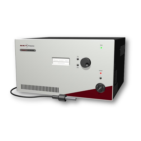
5 Interface 5.1 Front Panel The front panel of the SuperK EXTREME contains display and buttons for control of the system. Figure 5-1: Front panel of SuperK EXTREME Front Panel Display: Displays the state of the system and the operating level. The... -
Page 22: Back Panel
The system with possible accessories powered via the External Bus dissipates in total maximum 400 W. Main Power Switch The main power switch turns the SuperK EXTREME ON/OFF. Power LED The Power LED emits green light when the SuperK EXTREME is turned on. P a g e | 21... -
Page 23: External Bus
5.2.2 External Bus The External Bus on the back of the SuperK EXTREME system is a digital bus interface and 12 volt supply for external accessories. Pin Connections The table below provides the pin-out on the External Bus. Pin no. -
Page 24: Output Control
5.2.3 Output Control Output Control The warranty of the unit is measured by the usage of the booster incl. non-linear fiber. For some application high output power is not required at all time, but fast turn on time is important. For these applications the external enable option allows the user to obtain light when required, which increases the number of usage hours of the system. -
Page 25: Interlock
5.2.4 Interlock The SuperK EXTREME is a class 4 laser. Thus it is equipped with a door switch interlock connection in accordance with the laser safety regulations. The “Interlock” connector on the back panel contains terminals for an external door switch or interlock. - Page 26 Assembly For assembly of the LEMO connector with an interlock system please follow the procedure described in the table below. Step Illustration Strip cable and prepare soldering. Solder wire to connector pins (two gold deposited pins). Side view Assemble soldered parts with strain relief and the two cuff parts.
-
Page 27: Leds
USB connection. The 5 V LED on the back of the SuperK EXTREME is an indicator for the 5 volt supply voltage on the mainboard inside the SuperK EXTREME. When the system is powered up and if the supply voltage is correct the LED emits a green color. -
Page 28: Pulse Monitor
10 volt will turn it up to what level is defined by the Setpoint level, which can be seen on the front of the SuperK EXTREME system. So if the Setpoint for example is set to 50 % in Modulated Power mode and the voltage on the Modulation Input is 5 volt, then the output power from the SuperK EXTREME system will be at 25 %. -
Page 29: External Feedback (Option)
External Power Monitor on e.g. SuperK SELECT or other NKT Photonics accessories. For further information on how to utilize external feedback on the SuperK Extreme system, please refer to our “Application Note for External Modulation and Feedback”... -
Page 30: Optical Output
5.2.13 Optical Output The SuperK EXTREME has an armored fiber delivery, terminated by a collimator, see figure below. The collimator consists of two parts: Collimator housing: outer diameter 28 mm Collimator tube: outer diameter 12 mm Please refer to section 12.1 for further details regarding collimator dimensions.. -
Page 31: Rf-Driver Interface (Option)
The collimator could also be fixed in a ½-inch mount. 5.2.14 RF-Driver Interface (Option) On SuperK EXTREME systems with internal RF-Driver for SuperK Select or SuperK Cross, the system will have the following additional RF-Driver interface on the back. Figure 5-10: RF-Driver interface... -
Page 32: Air Outlet
5.2.15 Air Outlet The SuperK EXTREME is cooled down with air pulled in from the air inlet on the two sides and the front panel and blown out via the air outlet on the back. The system features five fans, one small fan in the bottom and four larger fans above. The four larger are all electrically controlled, i.e. -
Page 33: Operation
Clicking on the Emission button again will turn on laser emission with the same power level as before turning off. Table 6-1:First time installation and start-up procedure for the SuperK Extreme The SuperK EXTREME is now ready for use. P a g e... -
Page 34: Everyday Operation Via The Front Panel
6.3 Everyday Operation via the Front Panel Turning On Follow these steps for turning the system on: Step Switch the main power switch on the back panel on. When prepared for emission, turn the key-switch on the front panel to “ON” position. Click on the return button [] to reset the Interlock. -
Page 35: System Menu
If the interlock signals in the External Bus and Interlock connectors on back of the SuperK EXTREME are not closed/short connected as described in section External and Interlock, then the display will show up with following messages... -
Page 36: Operating Mode
ON. 7.1 Operating Mode The SuperK EXTREME can be operated in either Constant current or Constant power mode. In Constant current mode the pump current in the booster is held constant at the desired level, whereas the output power is held constant at the desired level in Constant power mode. -
Page 37: Pulse-Picker Ratio
External Feedback input. Warning It is very important that the SuperK EXTREME system has a valid feedback signal as it otherwise cannot operate correctly. If an incorrect signal is applied to the External Feedback connector and the system is set to lock to this signal it may turn up the optical power to its maximum level. -
Page 38: Input Readouts
SuperKontrol 2.0 manual about how to install and use the SuperKontrol 2.0 software. Date and Time If Date and time is chosen in the Status display sub-menu, the SuperK EXTREME will read out current date and time from the systems internal clock. -
Page 39: Date And Time
7.5 Date and Time The system contains an internal clock with battery back-up. The clock was set automatically during manufacturing of the system to Central European Time. If desired the date and time can be adjusted. Change Date and To change the date and time, click on the Enter button to enter the system menu. Turn the turning knob until the display says System menu ... -
Page 40: Display Backlight
7.8 Serial Numbers View Serial The SuperK EXTREME consists of a number of modules. To view the serial Numbers numbers of these modules and possible external accessories connected to the External Bus, click on the Enter button to enter the system menu. Turn the turning knob until the display says System menu ... -
Page 41: Firmware Versions
7.9 Firmware Versions View Firmware As for the serial numbers, it is possible to view the firmware revisions in the internal Versions modules and on external accessories connected to the External Bus. To view the Firmware versions, click on the Enter button to enter the system menu. Turn the turning knob until the display says System menu ... -
Page 42: Computer Controlled Operation
Labview based interface to the SuperK System. The driver is available through our Software Development Kit (SDK). USB Cable To connect the SuperK EXTREME to a computer, a standard USB cable A to B should be used. Figure 8-1: USB cable A to B... -
Page 43: Supercontinuum Generation
As the spectral broadening is caused by non-linear effects it will increase with the input pulse power. Accordingly, the width of the spectral output increases with the output power. Spectral output The figure below shows the output spectrum of a SuperK EXTREME at output power levels of: 4.5 W 2.8 W C. -
Page 44: Pulse-Picker
9.4 Reflection monitor Reflection The SuperK EXTREME is equipped with a reflection monitor to avoid that a back reflection can damage or destroy the system. In case the detection on the reflection monitor exceeds the present limit, the system will shut down and error code “Code 48, 5 0x65”... -
Page 45: Constant Power And Constant Current Mode
Remove all components after the collimator. Be sure to dump the output power in an appropriate beam dump, e.g. a large power meter. If the alarm shows up again, the reflection problem is internally in the SuperK EXTREME. Please note the set point value where the alarm appears. -
Page 46: Service & Support
Storage If required the SuperK Extreme should be stored in a dry and cool place (15-20°C). The optical output should be protected using the collimator holder on the backside of the SuperK Extreme unit. Avoid exposing the unit to vibrations or mechanical shock. -
Page 47: Literature
11 Literature Supercontinuum generation in photonic crystal fiber. John M. Dudley et al. Reviews of Modern Physics, Vol. 78, Oct-Dec 2006, page 1135-1184 A topical review of numerical and experimental studies of supercontinuum generation in photonic crystal fiber is presented over the full range of experimentally reported parameters, from the femtosecond to the continuous-wave regime. -
Page 48: Electrical And Mechanical Specifications
12 Electrical and Mechanical Specifications Parameter Conditions Value Unit Temperature range Ambient temperature 15 to 37 °C Humidity Non condensing 20 to 80 Supply voltage 100 to 240 Power dissipation Max. 400 Height 249.8 Width See drawing below 443.0 Depth 376.8 17 –... -
Page 49: Collimator Dimensions
12.1 Collimator Dimensions Dimensions: All dimensions in millimeters. P a g e | 48... -
Page 50: Accessories For The Superk Extreme
SuperK GAUSS even allows the tuning of the center wavelength of each band over 200nm. Connecting the GAUSS to the SuperK EXTREME is very simple and shares the same Plug’n’Play platform common to all SuperK accessories. P a g e... - Page 51 SuperK Split is a passive filter accessory which allows the SuperK spectrum to be divided into two spectral outputs. This is important in applications where light from one sub- area of the spectrum is desired and light outside this spectrum is parasitic. In its standard form, the SuperK SPLIT provides two outputs: Visible and nIR.
- Page 52 NKT Photonics Blokken 84 3460 Birkerød Denmark Phone: +4543483900 Fax: +4543483901 www.nktphotonics.com...
Need help?
Do you have a question about the SuperK EXTREME and is the answer not in the manual?
Questions and answers