Table of Contents
Advertisement
Quick Links
Advertisement
Chapters
Table of Contents

Related Manuals for NKT OneFive Origami XP Series


Summary of Contents for NKT OneFive Origami XP Series
- Page 1 OneFive Origami XP-Series High Energy Industrial Femtosecond Laser PRODUCT GUIDE...
- Page 2 PRODUCT GUIDE This guide includes the following NKT Photonics Lasers: OneFive Origami XP Air Cooled High Energy Industrial Femtosecond Laser delivering up to 40 micro Joules of pulse energy with an Air Cooled Chassis OneFive Origami XP Water Cooled High Energy Industrial Femtosecond Laser delivering up to 40 micro Joules of...
-
Page 3: Guide Overview
The paper copy of these guides are included with your laser however they can also be downloaded from: https://www.nktphotonics.com/lasers-fibers/support/product-manuals/ Documentation A USB memory stick is included. It contains documentation for all NKT Photonics products including this laser. Terminology The guide may refer to both the Origami XP and Origami XPS lasers as “the laser”. - Page 4 Chapter 2 — Describes the chassis models available within “Chassis Types” • the OneFive Origami XP series. Chapter 3 — Includes information and procedures on “Mechanical Installation” • how to correctly install the laser chassis. Procedures within this chapter focus on providing adequate temperature regulation.
- Page 5 Added information Lasers are highly dangerous devices that can cause serious injury and property and Safety Notices damage. This guide use the following symbols to either highlight important safety information or provide further information in relation to a specific topic. Note: Highlights additional information related to the associated topic and/or pro- vides links or the name of the NKTP guides describing the additional information.
-
Page 7: Table Of Contents
CONTENTS Guide Overview ........................3 Documentation ....................... 3 Terminology ......................3 TABLES ........................15 FIGURES ........................17 PROCEDURES ....................... 19 Section 1 ORIGAMI XP & XPS DESCRIPTION 1 Laser Description ......................23 Power supply ....................... 24 Safety ........................24 Harmonic generator modules ................. 25 Temperature regulation .................. - Page 8 Status LEDs ........................ 35 Chassis labels ......................37 2 Chassis Types ........................39 Air-cooled OneFive Origami XP ................39 Water-cooled OneFive Origami XP ..............40 Section 2 INSTALLING THE LASER 3 Mechanical Installation ....................43 Installation process .................... 43 Installation environment ..................43 Installation procedures ..................
- Page 9 AOM shutter logic ....................59 Examples of Laser Output Pulses using DGI ..........60 Analog Modulation Input ..................62 AMI optical pulse power control ..............62 Using the Analog Modulation Input ............... 63 Dual DGI and AMI control ..................64 Section 3 OPERATING THE LASER 6 Communicating with the Laser ..................67...
- Page 10 GUI settings ......................83 GUI menu ........................87 Serial monitor ......................87 Application log ......................87 GUI – control panel ....................89 Operating modes ....................89 Wavelength selector ..................89 Energy ........................89 Repetition rate ..................... 90 Division factor control ..................91 Harmonic generator operation ................
- Page 11 ly_oxp2_mode? ......................110 ly_oxp2_temp_status .....................110 ly_oxp2_digiop ......................111 ly_system_info ......................113 ly_system_info ......................113 ls? ..........................114 ls_temp_setpoint? ....................116 ls_temp_setpoint ......................116 ls_temp_setpoint_SHG ..................117 ls_temp_setpoint_THG ..................118 ls_temp_oven? ......................118 ls_humidity? .......................119 ls_wavelength ......................119 ls_status? ........................120 ls_output_power? ....................121 ls_crystal_curSpot? ....................121 ls_crystal_setSpot ....................121 ls_crystal_curRuntime? ..................122 ls_crystal_maxRuntime? ..................123 ls_crystal_allRuntimes? ..................
- Page 12 Standby ........................132 LaserOn ........................132 Set Energy .........................133 Get Emitted Energy ....................133 Operating Time ......................133 Degeneration Indicator ..................134 11 SPI Control ........................135 SPI Function ......................135 General .........................135 Appendices A Specifications ........................139 B Service and Support Information ................145 Servicing the laser ....................145 Opening the laser chassis ................145 WARRANTY VOID IF REMOVED label ............145 Support Contact Details ..................145...
- Page 13 F Unpacking the Laser ...................... 157 Unpacking the laser ....................157 Handles ........................ 157 Unpacking procedure ..................157...
-
Page 15: Tables
TABLES Table 1: Origami laser series output specifications @ 1030 nanometers ....23 Table 2: Multi-harmonic generator beam output specifications .......27 Table 3: Optical parameters @ 1030 nanometers ............29 Table 4: Optical interface parameters ................30 Table 5: RS-232 COM port settings................. 32 Table 6: Door switch interlock operation............... - Page 16 Table 29: Optical performance ..................139 Table 30: Interfaces ......................140 Table 31: Mechanical dimensions - laser and power supply ........140 Table 32: Operating and storage environment ............140 Table 33: Electrical ......................140 Table 34: Safety and regulatory compliances .............141 Table 35: X4 RS-232 serial port pin assignments............147 Table 36: X2 3W3 D-SUB pin assignments ..............147 Table 37: X3.1 CAN bus pin assignments..............148 Table 38: X3.2 CAN bus pin assignments ..............148...
-
Page 17: Figures
FIGURES Figure 1: Origami XP or XPS general view - front and rear panels ......23 Figure 2: Power supply ...................... 24 Figure 3: Second Harmonic Generation Module - general view ......26 Figure 4: Third Harmonic Generation Module - general view ........27 Figure 5: 3-port Third Harmonic Generator (3P THG) Module - general view .. - Page 18 Figure 29: Error code and message example ............. 82 Figure 30: GUI settings ...................... 83 Figure 31: View settings ..................... 84 Figure 32: Laser system temperatures ................84 Figure 33: System details ....................85 Figure 34: System settings ....................86 Figure 35: Menu items .......................
-
Page 19: Procedures
PROCEDURES Procedure 1: Connection steps to make when installing the laser ......51 Procedure 2: Connecting the door interlock circuit........... 54 Procedure 3: Connecting power ..................54 Procedure 4: Using the Analog Gate Input..............63 Procedure 5: Connecting the Graphical User Interface to the laser ..... 68 Procedure 6: Connecting the Command Line Interface to the laser..... -
Page 21: Origami Xp & Xps Description
SECTION 1 ORIGAMI XP & XPS DESCRIPTION This section provides a description of the laser and its chassis types. “Laser Description” on page 23 • “Chassis Types” on page 39 •... -
Page 23: Laser Description
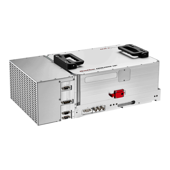
Laser Description The OneFive Origami XP and Origami XPS are a series of single chassis, microjoule femtosecond lasers. The lasers provide a stable and low-noise pulsed beam at a wavelength of 1030 nanometers with high pulse contrast. Due to their hardened construction, the lasers can operate in a wide range of ambient conditions. -
Page 24: Power Supply
The laser requires an external 24 VDC power source connected to its power input connector. The power can be supplied from your own source or from an NKT Photonics power supply. The NKTP power supply is controlled by a key switch as a safety feature to prevent unauthorized operation. -
Page 25: Harmonic Generator Modules
Harmonic generator As an accessory option, a harmonic generator can be mounted on the laser to modules convert the output beam wavelength. Depending on the wavelength conversion required, NKTP can supply the following harmonic generators for use with the laser: Second Harmonic Generator (SHG) –... -
Page 26: Figure 3 Second Harmonic Generation Module - General View
SHG (dual port) An SHG module converts the laser’s 1030 nanometer pulse wavelength to a green output pulse at 515 nanometers. Each pulse contains up to 20 microjoules (or up to 40 microjoules for the XPS) of energy with a width of less than 400 femtoseconds. The modules are hermetically sealed and include a desiccant to support operation in industrial environments. -
Page 27: Table 2 Multi-Harmonic Generator Beam Output Specifications
Interlock and Power/External Bus LED 9 Optional IR output aperture with shutter DC Power Connector M8 Note: Compatibility and performance of the SHG and THG may vary. Contact NKT Photonics Support (see B) for information on using the modules with your Appendix laser. -
Page 28: Temperature Regulation
Figure 5 3-port Third Harmonic Generator (3P THG) Module - general view Beam dump 6 3P THG height adjustment bolts Purged air inlet Green output aperture with shutter Interlock and Power/External Bus LED 8 UV output aperture with shutter DC Power Connector M8 9 Optional IR output aperture with shutter External bus input Temperature... -
Page 29: Optical Parameters
Optical parameters A subset of the laser’s optical output parameters are listed in and the typical Table 3 temporal performance is shown in 6. For a complete list of optical parameters Figure refer to Table 29, “Optical performance,” on page 139. -
Page 30: Optical Interface
Optical interface Optical interface The laser aperture is placed near the center of the front panel as shown in 7. The aperture is covered by a mechanical shutter which must be Figure manually slid open before the laser emission is turned on. Table 4 Optical interface parameters Parameter Specification... -
Page 31: Figure 8 Front Panel Electrical Connections
Electrical interfaces To control and manage the laser, a PC or automated system can be connected to serial or bus interfaces. Finally, to synchronize and match output pulse timing and amplitude with the target application, an output trigger port and input modulation gates can be employed. -
Page 32: Power Supply
Electrical interfaces listed in 5. Note that the port’s communication latency is less than 0.2 Table seconds. Table 5 RS-232 COM port settings Setting Value Baud Rate 38.4 kbps Data Bits Parity None Flow Control None Transmitted Append LF Text Received Text Mono-spaced Warning:... -
Page 33: Digital Gate Input
Electrical interfaces Table 6 Door switch interlock operation Pin 1 Pin 2 Pin 15 Door Closed +3.3 VDC +3.3 VDC +3.3 VDC Laser Logic Amplifier ON AOM Open Door Open +3.3 VDC 0 VDC 0 VDC Laser Logic Amplifier OFF AOM Closed Interlock Defeater The laser includes an interlock defeater. -
Page 34: Trigger Output
The trigger output signal is synchronized with the AOM. If the AOM is fully closed, there is no trigger signal at the output. Laser Control Graphical User NKT Photonics provides a special Origami XP Graphical User Interface (GUI) Interface similar to NKT Photonics CONTROL software. -
Page 35: Command Line Interface
Status LEDs The laser can be controlled and configured from a PC with the Origami XP application installed on it. The PC must be connected to the laser using the RS- 232 serial port on the front panel. Once connected, you can use the GUI to control the laser’s emissions and adjust its power and pulse rate settings. -
Page 36: Table 8 Status Leds
Status LEDs Figure 10 Status LEDs Table 8 Status LEDs LED Name Condition Description Laser ON Enabled ON Red Laser is ON. If the shutter is open, the laser emits class 4 radiation Laser ON Disabled ON Red Laser is ON, but emission is reduced to low values as the internal AOM is still closed. -
Page 37: Chassis Labels
Chassis labels Chassis labels The OneFive Origami XP chassis includes multiple labels that indicate hazards and regulatory or manufacturing information. The labels are located on several panels as described in with the front panel shown in Table 9 Figure Table 9 Chassis labels Label Panel Description... -
Page 38: Figure 11 Front Panel Label Locations
Chassis labels Figure 11 Front panel label locations Caution 5. Classification - Emission Hazards Class 4 Laser Radiation Warning 6. Product Information Laser Aperture 7. Laser Radiation Warning Customer Part Number... -
Page 39: Chassis Types
Chassis Types The OneFive Origami XP Laser series consists of two separate chassis models, each classified by its thermal regulation system. This chapter describes the characteristics of the thermal regulation for each chassis type. Air-cooled OneFive Origami XP The air-cooled chassis of the OneFive Origami XP laser uses a fan plenum shelf with five fans to thermally regulate the laser operation. -
Page 40: Water-Cooled Onefive Origami Xp
Water-cooled OneFive Origami XP Water-cooled OneFive Origami XP This chassis uses water-cooled channels to regulate the temperature of the laser operation. The laser is equipped with two male straight hose couplings through which the inlet and outlet cooling water is circulated. The water is cooled using an external cooling system consisting of a chiller combined with a controller that has at the minimum, a temperature set point and flow control capability. -
Page 41: Installing The Laser
SECTION 2 INSTALLING THE LASER This section describes how to install the laser and includes the chapters: “Mechanical Installation” on page 43 • “Connecting the Laser” on page 51 • “Digital Gate and Analog Modulation Inputs” on page 59 •... -
Page 43: Mechanical Installation
Mechanical Installation The lasers generate a substantial amount of heat that must be dissipated. To dissipate the heat, the lasers are available in two different chassis versions defined by their temperature regulation system. This chapter provides information on how to mechanically install the air and water-cooled variants of the laser. -
Page 44: Installing The Air-Cooled Chassis
Installing the Air-cooled chassis air flow is adjusted based on the lasers operating temperature. There should be a clearance gap in front of the intake grill and exhaust vents to allow the free flow of air. Water-cooled The laser is cooled by water that is pumped and circulated through the laser from an external chiller. -
Page 45: Table 11 Air-Cooled Installation Requirements
Installing the Air-cooled chassis Table 11 Air-cooled installation requirements Requirement Specification Instruction Clearance 200 mm Specification is the minimum clearance from the chassis’ side panels to any nearby airflow obstruction. See Figure 1 mm Specification is the minimum clearance from the chassis top and bottom panels. -
Page 46: Installing The Water-Cooled Chassis
Installing the water-cooled chassis Installing the water-cooled chassis lists the installation requirements for the water-cooled version of the Table 12 laser. Table 12 Water-cooled installation requirements Requirement Specification Instruction Clearance 1 mm Specification is the minimum clearance from the any of the chassis panels. -
Page 47: Coolant Specifications
Installing the water-cooled chassis Figure 15 Chiller with water-cooled laser Industrial Water Chiller Straight Hose Couplers Polyurethane Tubing Coolant For the water-cooled chassis, you must use an industrial water chiller that meets specifications the specification in 13. The coolant can flow in either direction through the Table laser, meaning the coolant supply and return hoses from the chiller can be connected to either of the laser’s straight hose couplers. - Page 48 Installing the water-cooled chassis To protect the aluminum cooling circuit, it is recommended to use a coolant containing an anti-corrosive additive. Required water flow and water temperature may vary and is dependent on the actual optical system parameters. Caution: The cooling system is constructed entirely from aluminum. To avoid cor- rosion, make sure not to connect other items to the cooling circuit except when agreed with NKTP.
-
Page 49: Second Harmonic Generator Installation
Installing the water-cooled chassis Installing second or third harmonic generators NKTP harmonic generators must first be integrated to the laser by qualified NKTP personnel. Contact NKTP support for further information. See “Support Contact Details” on page 145. Second harmonic To install the generator refer to the NKTP bulletin: generator Installing an NKTP Second Harmonic Generator with Origami X-series lasers installation... - Page 50 Installing the water-cooled chassis...
-
Page 51: Connecting The Laser
Connecting the Laser Before operating the laser, follow the procedures in this chapter to ensure its correct and safe operation. Connection steps lists the recommended steps to perform when connecting the laser. Procedure 1 Procedure 1 Connection steps to make when installing the laser Step Port Ground the laser using the included... -
Page 52: Connecting The Safety Interlock
Connecting the safety interlock Connecting the safety interlock To comply with safety regulations and help provide a safe operating environment, the safety interlock of the laser must be connected to a switch activated by an access door to the laser’s enclosure. When the connected switch is opened by the door, it opens the interlock circuit which turns off laser emissions. -
Page 53: Connecting An Interlock Switch
Disabled Caution: Do not short-circuit the Interlock input. Short-circuiting the interlock cir- cumvents safety regulations and NKT Photonics does not take liability for any in- juries or damage caused by doing so. Caution: The switch connected to the interlock must be of an approved type. Fur- ther, the switch must be installed in a manner so that its operation cannot be fixed in the closed state using a tool. -
Page 54: Connecting Power
Connecting power Procedure 2 Connecting the door interlock circuit Action Install a switch that opens when the door accessing the laser enclosure is opened. The switch must comply with safety regulations. Connect the switch to the prewired interlock plug using insulated wire. The wire gauge should be at a minimum 26 AWG with a maximum length of five meters. - Page 55 Connecting power Action Set the Emergency Stop button to the deactivated position by turning it clockwise slightly until it snaps out to the outward position. Press the power toggle switch on the rear panel of the power supply to the ( I ) position. Position To turn on the laser power, turn the power supply Key to ON position.
-
Page 56: Ac Power Cord
Connecting the Trigger Output Figure 18 Power supply Status LED 2. Emergency Stop Button Power ON/OFF Key Switch Power Supply Operation When the key-switch is turned to “On”, electrical power is supplied to the laser and the laser will enter “Listen” mode. When the key-switch is turned to “Off”, electrical power is completely shut off from the laser. -
Page 57: Effective Repetition Rate
Division Factor e_div on page 106 Division factor control on page 91 Note: The Trigger type can also be programmed at the factory. Contact NKT Pho- tonics support for more information. See “Support Contact Details” on page 145. Table 15 Trigger output specification... - Page 58 Connecting the Digital Gate and Analog Modulation Inputs...
-
Page 59: Digital Gate And Analog Modulation Inputs
Digital Gate and Analog Modulation Inputs This chapter provides details on how to apply digital and analog signals to the Digital Gate Input (DGI) and Analog Modulation Input (AMI) ports (see Figure 8 on 31) to control the laser’s output emissions. The interfaces are described in page sections: “Digital Gate Input”... -
Page 60: Examples Of Laser Output Pulses Using Dgi
Digital Gate Input Setting the DGI port logic The port logic can be set to either “Active-Low” or “Active-High”. If “Active-Low” is selected, a low signal level at the port will enable laser emission from the AOM. If “Active-High” is selected, a high signal level at the port will enable laser emission from the AOM. -
Page 61: Figure 19: Dgi Settings - Active-Low Logic
Digital Gate Input Note: For single optical pulse selection, the applied digital signal must be at least 100 ns long to meet the acquisition time window width, and shorter than the laser period to prevent overlapping with the next optical pulse. DGI signal constraints The AOM works in “Burst Mode”... -
Page 62: Analog Modulation Input
Analog Modulation Input Figure 20: DGI settings – ACTIVE-HIGH logic Analog Modulation Input The Origami XP/S platform offers the possibility to externally modulate the output power through an Analog Modulation Input (AMI). The laser must be simply configured to operate in external mode. This mode configures the laser to set the pulse output power level based on the voltage level applied to the AMI. -
Page 63: Using The Analog Modulation Input
Analog Modulation Input Table 18 Analog Modulation Input signal specifications Parameter Value Analog input voltage range Note: 0 VDC sets the laser output power to 0-2.6 VDC minimum power and 2.6 V sets it to maximum Input impedance 1 kΩ Analog bandwidth 1 MHz Acquisition time... -
Page 64: Dual Dgi And Ami Control
Dual DGI and AMI control Dual DGI and AMI control The laser supports simultaneously monitoring signals at both the DGI and AMI ports. Utilizing the ports simultaneously means that the output pulses can be selected (ON-DEMAND) while their pulse energy level is modulated. Figure 22 shows an example of Dual DGI and AMI control. -
Page 65: Operating The Laser
SECTION 3 OPERATING THE LASER This section describes how to manage and operate the laser and includes the chapters: “Communicating with the Laser” on page 67 • “Turning ON the Laser” on page 71 • “Origami XP GUI” on page 77 •... -
Page 67: Communicating With The Laser
Communicating with the Laser The laser can be managed using multiple methods: NKT Photonics Origami XP (GUI) software installed on a PC • Command Line Interface (CLI) from a remote terminal • CAN bus system • SPI Interface • This chapter focuses on how to obtain and install the GUI and connect the PC using serial RS-232 connectivity. -
Page 68: Connecting The Laser To A Pc
Using the serial to USB adapter cable included with the laser, connect a PC’s USB port to the laser’s RS-232 port. Note: To connect a USB port to the laser’s serial port you must install NKT Photonics USB Driver. The driver software is available on: https://www.nktphotonics.com/lasers-fibers/support/software-drivers/... -
Page 69: Procedure 6 Connecting The Command Line Interface To The Laser
Using the serial to USB adapter cable included with the laser, connect a PC’s USB port to the laser’s RS-232 port. Note: To connect a USB port to the laser’s serial port you must install NKT Photonics USB Driver. The driver software is available on: https://www.nktphotonics.com/lasers-fibers/support/software-drivers/... - Page 70 Connecting the laser to a PC...
-
Page 71: Turning On The Laser
Turning ON the Laser Safety Before you turn on the laser, ensure that you are completely familiar and follow all safety information and recommendations stated within this document and the guide: OneFive Origami XP-series Laser Safety, Handling and Regulatory Information You must follow all safety regulations required at the location where the laser will be operated. -
Page 72: Controlling The Laser Emissions
Controlling the laser emissions Controlling the laser emissions Turning On the To enable emission using: Laser the GUI follow the steps in Procedure • the CLI use Procedure • Warning: If the PC controlling the laser is disconnected, laser emission will remain ON. Note: The laser is equipped with internal temperature sensors that monitor the temperature of sensitive components. - Page 73 Controlling the laser emissions Action In the GUI Control panel, set the laser’s base frequency and division factor using the “Repetition Rate” and “Division Factor” slider controls. To change them, click hold the red slider and drag it left or right. Alternatively, you can directly enter the frequency in MHz units and division factor by typing the value into the input boxes at the...
- Page 74 Controlling the laser emissions Action To set the laser’s emitted pulse energy level use the “Power control” slider. To change the power, click and hold the red slider to adjust its position along the bar. Alternatively, you can directly enter the power Direct power level in nanojoules units by typing the value Slide the control...
-
Page 75: Procedure 8 Turning On The Laser Using The Cli
Controlling the laser emissions Procedure 8 Turning on the laser using the CLI Action On the rear panel of the power supply, toggle the power switch to ON. Then on the front panel of the power supply, turn the key switch on the power supply front panel to the ON position. -
Page 76: Errors
Controlling the laser emissions Action To configure the emitted power and pulse energy issue the command: “e_power=power_value” as shown in the example below. >e_power 2500 >e_power? Setted laser power in relative unit: 2500 To configure the emitted power to be varied by a DC voltage applied at the AMI port, issue the command “emode operating_mode”... -
Page 77: Origami Xp Gui
Origami XP GUI Origami XP GUI overview The GUI includes multiple panels and a selection of menu drop down items in the upper left corner. Using the Window drop down menu, you can add or remove the displayed panels and panels can be dragged within the main window or into separate windows. -
Page 78: Relocating Panels
Origami XP GUI overview Relocating panels The panels displayed by GUI can be dragged to other positions within the main interface or apart as separated floating panels. describes how to Procedure 9 move a panel: Procedure 9 Relocating panels Action Left click hold the top title bar of any panel. -
Page 79: Toggling Panels
Origami XP GUI overview Toggling Panels Use the Menu > Window drop down menu to check and uncheck panels to be displayed. A blue check mark indicates the panel is displayed. Figure 26 Panels dragged outside the main window Check the panels names to display them Note: Clicking the X in the upper right corner of any panel will also close it. -
Page 80: Status Panel
Status panel Status panel The Status Panel provides status indicators, error messages, DGI gate logic status, emission control function and a settings menu. Figure 28 Status panel indicators Click Status indicators Warning: The panel displays the following indicators: Power On Indicates if power is connected to the laser. - Page 81 Cycle the key switch to OFF and then ON b) Close the external interlock circuit Watchdog timeout a) Reconnect NKT Photonics CONTROL. b) Reset the interlock by cycling the key switch. Oven fault Indicates an error with a harmonic generator oven: ON Red –...
-
Page 82: System Info
Status panel Note: Error messages and codes are listed in E. The system will display Appendix warnings and error messages and codes in the status panel as shown in the ex- ample in Figure Figure 29 Error code and message example System info The System Info section shows the following: Laser Serial Number... -
Page 83: Emission Button
Status panel The Standby button indicator will light ON Amber when the mode is activated. It will blink during the warm up period and remain steady ON when the operating temperature is reached. Emission button The Emission button turns the laser emission ON, Emissions Enabled mode – 72. -
Page 84: Table 20 Laser Operating Temperatures
The ranges for the sensors should fall within the values shown in If the temperatures reported are not within the operating range, contact Table NKT Photonics support (see “Support Contact Details” on page 145). Figure 32 Laser system temperatures... -
Page 85: Figure 33 System Details
Status panel Temperature Sensor Number Operating Temperature Range Minimum: 20°C Maximum: 30°C Minimum: 15°C Maximum: 45°C Minimum: 20°C Maximum: 30°C Minimum: 48°C Note: Early legacy models only Maximum: 52°C System details This menu displays the details of the laser as shown in . -
Page 86: Figure 34 System Settings
Status panel System settings Use this menu to set the Digital Gate Input (DGI) logic. The DGI function is ON whenever the laser is turned on and the function cannot be turned OFF. The circuit constantly monitors the voltage reading (logic level) at the port and either opens or closes the AOM. -
Page 87: Gui Menu
GUI menu GUI menu There are four drop down menus in the main control window as highlighted in 35. Click on the items in the menu to reveal the drop down menus. Figure Figure 35 Menu items Menu Item Function File Exits the GUI program Connect /... -
Page 88: Figure 37 Serial Monitor
GUI menu Figure 37 Serial monitor Clear the log Save the log to file Print the log The panel is enabled by placing a check mark on the Window pull down menu next to the Application Log item. To close the panel click on the upper right corner “X”. -
Page 89: Gui - Control Panel
GUI – control panel GUI – control panel Operating modes For the OneFive Origami XP GUI the control panel can be configured to present different operating mode controls. Control of the laser emissions varies according to the mode chosen. To select one of the modes listed in Table click on the operating mode menu located on the right side of the panel (See 38) . -
Page 90: Repetition Rate
GUI – control panel to 0 to 40 microJoules using the scale selection drop down menu on the right. Immediately above the slider on the right, the measured output energy of the laser is displayed in microJoules. Figure 39 IR Energy control Measured laser output energy (harmonic energy optional... -
Page 91: Division Factor Control
Harmonic generator operation Figure 40 Repetition rate Laser output repetition rate Repetition rate slider and Current Set manual input field Point Slider Division factor control slider Division factor As shown at the bottom of 40, a division factor control can also be Figure control configured. -
Page 92: Figure 42 Wavelength Selection - Harmonic Generator Only
Harmonic generator operation Figure 42 Wavelength selection - harmonic generator only Wavelength selection (w/harmonic generator only) Current Set Point Slider... -
Page 93: Shg/Thg Settings
Harmonic generator operation SHG/THG settings Oven The setpoint temperature of the conversion stage can be controlled with the SHG and THG sliders shown in 43. The conversion efficiency is affected by Figure this temperature. Do not change the setpoint temperature without first contacting NKTP support, see “Support Contact Details”... -
Page 94: Dwls Wavelength Feature
Harmonic generator operation Figure 44 Selecting the crystal spot All spot runtimes button with current spot runtime Crystal spot selection slider and manual input Displaying runtime The runtime for the currently selected spot is displayed above the crystal spot selection bar. To display runtimes for all crystal spots click the “Show all spots” button just above the Current spot hours on the right side of the selection bar. -
Page 95: Figure 46 Dwls Enable/Disable
Harmonic generator operation Figure 46 DWLS enable/disable Click the DWLS enable or disable radio buttons If DWLS is enabled, you can save the AOM energy level (μJ) set for each wavelength (λ) by adjusting the Energy control to the desired level. When the level is set, click the Set AOM energy level button shown in Figure Figure 47 DWLS wavelength AOM set control... -
Page 96: Figure 48 Dwls Energy Settings
Harmonic generator operation Figure 48 DWLS energy settings Saved energy level μ displayed in J for λ each... -
Page 97: Command Line Interface - Cli
Command Line Interface – CLI This chapter provides a description of the commands that can be issued using the CLI. A brief listing of the commands for the laser is given in and for Table 22 the harmonic generators in 23. -
Page 98: Table 23 Harmonic Generator Cli Commands
Table 23 Harmonic generator CLI commands Command Function Description Link Displays the harmonic generator “ls?” on page 114 commands and a brief description of each. ls_temp_setpoint? Displays the temperature control set “ls_temp_setpoint?” on page 116 point for the module oven(s). ls_temp_setpoint Sets the temperature control set “ls_temp_setpoint”... -
Page 99: Ly_Oxp2_Listen
ly_oxp2_listen Usage None Example >h Laser Configuration: Origami - 10 XP MR Basic command list for the laser ------------------------------------------------------------- ---------------------------------- ly_oxp2_listen: Sets the laser to Listen mode ly_oxp2_standby: Sets the laser to Standby mode - warning class 4 laser emissions ly_oxp2_enabled: Turns the laser ON and enables emission - warning class 4 laser emissions... -
Page 100: Ly_Oxp2_Standby
ly_oxp2_standby ly_oxp2_standby Description This command sets the laser to the standby status. Warning: In standby mode, the residual leakage of the powered seed laser is still rated as class 4 radiation. Note: Thermalization of the laser (can take up to 15 minutes) Syntax ly_oxp2_standby Usage... -
Page 101: Ly_Oxp2_Output_Disable
ly_oxp2_output_disable Before enabling emission with this command, ensure the aperture’s mechanical shutter is open and safety measures are employed. Example >ly_oxp2_enabled Standby -> ON enabled OnDisabled=ok OnEnabled=ok > ly_oxp2_output_disable Description This command disables the AOM. Use this command to disable laser emission through the AOM shutter, without disabling the laser amplifier Syntax ly_oxp2_output_disable... -
Page 102: Ly_Oxp2_Output
ly_oxp2_output? Warning: The command enables full Class 4 laser emissions when executed. Example >ly_oxp2_output_enable ly_oxp2_output_enable Enabling Laser output. >ly_oxp2_output? Laser output enabled. > ly_oxp2_output? Description This command displays the AOM status. Syntax ly_oxp2_output? Usage Use this command if you need to check if the AOM is enabled or disabled. The command shows the status of the AOM: AOM open –... -
Page 103: Ly_Oxp2_Power
ly_oxp2_power ly_oxp2_power Description This command is used to display and set the emitted pulse energy in nanoJoules. Syntax ly_oxp2_power [= pulse_energy |?] pulse_energy The pulse energy in nanoJoules Range: depends on the laser model – contact NKTP for more information. ? Displays the laser’s pulse energy in nanoJoules NOTE: Do not enter a space between the command... -
Page 104: E_Power_Rel
e_power_rel Usage The e_power setting is a relative setting, the emitted energy and will depend on the setting of the base frequency and the division factor. The command can be applied while the laser is emitting a beam. Caution: For safety reasons, the e_power setting is reset to zero after any laser setting is modified. -
Page 105: E_Freq_Available
e_freq_available? Example >e_power_rel=42.45 Relative IR output power=42.45% >e_power_rel? Relative IR output power=42.45% > e_freq_available? Description This command displays the available base repetition rates (base frequency) and the index associated with it. The index base_freq_index can be used to change the base repetition rate using the command "e_freq" Syntax e_freq_available? Usage... -
Page 106: E_Div
e_div Syntax e_freq [= base_freq_index |?] base_freq_index A frequency index of the laser. Range: 0 to 11 where: Each index frequency setting is predefined for the specific laser. Indexes can be predefined at the factory with frequencies from 50 kHz to 1 MHz. NOTE: The range for each laser may differ and is set at the factory. -
Page 107: E_Mode
e_mode Syntax e_div [= division_factor |?] division_factor The repetition rate of the pulses emitted at the set base frequency can further be divided by this integer. Range: 1 to 10,000,000 ? Displays the laser’s division factor NOTE: Do not enter a space between the command and ‘?’. -
Page 108: Ly_Oxp2_Wvl
ly_oxp2_wvl Usage Internal: Select 2 (Internal) to set pulse power and energy using the e_power or ly_oxp2_power commands. External: Select 3 (External) to modulate the output pulse power using an analog voltage applied to the “Analog Input Gate”. See “Analog Modulation Input” on page SPI: Select 8 (SPI) for real time pulse to pulse energy to be controlled through the SPI port. -
Page 109: Ly_Oxp2_Dev_Status
ly_oxp2_dev_status? Example >ly_oxp2_wvl=1 ly_oxp2_dev_status? Description This command displays the operating status of the laser as displayed by the status LEDs on the back interface of the laser. Syntax ly_oxp2_dev_status? Usage Displays the ON/OFF condition of each status LED. The output is an 8 bit word in decimal form where each bit represents one of the status LEDs. -
Page 110: Ly_Oxp2_Mode
Refer to for the lasers proper operating temperatures. If the Table 20 temperatures reported are not within the operating range and displaying NOK status, contact NKT Photonics support (see “Support Contact Details” on page 145). This command is valid only for IR-only laser modules and legacy SHG and THG. -
Page 111: Ly_Oxp2_Digiop
ly_oxp2_digiop Example >ly_oxp2_temp_status ############################################################# ####################################### Origami-10 XP device: general temperatures_status (0-NOTok, 1- ok): 1 ------------------------------------------------------------- --------------------------------------- 1a.)Temperature 1 seting: 39.000 deg.C , Actual Temperature 1: 38.420 deg.C 1b.)Min Temperature 1 seting for ok status: 15.000 deg.C , Max Temperature 1 seting: 45.000 deg.C 1c.)Temperature 1 status (0-NOTok, 1-ok): 1 2a.)Temperature 2 seting: 42.000 deg.C , Actual Temperature 2: 41.990 deg.C... -
Page 112: Table 24 Setting The Dgi Gate_Logic Parameter
ly_oxp2_digiop Syntax ly_oxp2_digiop [= gate_logic |?] gate_logic The control logic setting of the DGI port. Range: 0 or 1 where: 0 = Active-Low Logic 1 = Active-High Logic ? Displays the logic setting for the DGI port. NOTE: Do not enter a space between the command and ‘?’. -
Page 113: Ly_System_Info
ly_system_info Example >ly_oxp2_digiop? ly_oxp2_digiop? Active digital gate logic:logic LOW (no connection) = AOM OPEN / logic HIGH = AOM CLOSED. >ly_oxp2_digiop=1 ly_oxp2_digiop=1 New digital gate logic:logic LOW (no connection) = AOM CLOSED / logic HIGH = AOM OPEN. >ly_oxp2_digiop? ly_oxp2_digiop? Active digital gate logic:logic LOW (no connection) = AOM CLOSED / logic HIGH = AOM OPEN. - Page 114 Usage None Example >ly_system_info Origami-10 XP MR Hardware:V3.2.5 Firmware:V5.02-660 SW_MAIN_006_OXP_5_02-660 Compiled on: Dec 10 2019 16:22:38 Serial number: SN3364 LDD device - Hardware: 8063-LDD, Software version: 210, Revision: 275 TEC device - Hardware: 8065-TEC, Software version: 272, Revision: 324 Timing Board S/N: 0159-73CE-C25E-FF98; MCU T/B: R-003 9; FPGA T/B: T-003 9 Device switch on time (Standby and up): 705 hours 17 minutes Laser Emission switch on time: 159 hours 17 minutes...
- Page 115 Example >ls? NKT harmonic generation module (address: 32 / type: 0x8d) Firmware version: 0.02 alfa Jul 19 2019 09:51:38 Bootloader version: 1.09 Slave Xmega Module serial number: PCB serial number: Available commands: ---------------------------------------- ls_temp_setpoint_SHG: Sets the module's SHG oven temperature setpoint in...
-
Page 116: Ls_Temp_Setpoint
For the THG, the command displays two temperatures and ranges as this module has ovens for both second and third harmonic conversion stages. Example >ls_temp_setpoint? NKT THG SHG Oven Setpoint=40.0 C Min=39.0 C Max=81.0 C NKT THG THG Oven Setpoint=40.0 C Min=39.0 C Max=81.0 C... -
Page 117: Ls_Temp_Setpoint_Shg
Caution: It is recommended that you do not adjust this temperature setting with- out guidance from NKTP. Example >ls_temp_setpoint? NKT THG SHG Oven Setpoint=40.0 C Min=39.0 C Max=81.0 C NKT THG THG Oven Setpoint=40.0 C Min=39.0 C Max=81.0 C >ls_temp_setpoint_SHG=42... -
Page 118: Ls_Temp_Setpoint_Thg
Caution: It is recommended that you do not adjust this temperature setting with- out guidance from NKTP. Example >ls_temp_setpoint? NKT THG SHG Oven Setpoint=40.0 C Min=39.0 C Max=81.0 C NKT THG THG Oven Setpoint=40.0 C Min=39.0 C Max=81.0 C >ls_temp_setpoint_THG=42... -
Page 119: Ls_Humidity
NKT SHG Oven Temperature=26.0 C > This example shows the output from an THG module with dual ovens, one each for the second and third harmonic stages: >ls_temp_oven? NKT THG SHG Oven Temperature=39.0 C NKT THG THG Oven Temperature=40.0 C > ls_humidity? Description Execute this command to display the relative humidity in percentage within the harmonic generator (SHG and 3P THG only). -
Page 120: Ls_Status
When the laser amplifier is ON, class 4 laser radiation leakage is emitted when the AOM is set to 0% or closed. Example >ls_wavelength? NKT SHG Current position=GREEN >ls_wavelength=0 NKT SHG Moved piezo stage to IR > ls_status? Description Executing this commands displays the module status. For use by NKTP support only. -
Page 121: Ls_Output_Power
Each crystal is subdivided into ten spots and the spot selected for use by the harmonic generator is shown with this command. Example >ls_crystal_curSpot? NKT THG Current crystal spot=1 > ls_crystal_setSpot Description This command sets the crystal spot used by the THG. -
Page 122: Ls_Crystal_Curruntime
You can use this command to select a new spot for use when for example, the maximum runtime of the currently selected spot is reached. Example >ls_crystal_setSpot=2 NKT THG Crystal spot will be changed to 2 >ls_crystal_curSpot? NKT THG Current crystal spot=2 > ls_crystal_curRuntime? -
Page 123: Ls_Crystal_Maxruntime
To gauge the total lifetime left for the crystal, use this command to display all spot runtimes in seconds. Example >ls_crystal_allRuntimes? NKT THG All runtimes=9939 0 57 0 0 0 0 0 0 0 > Command Line Interface – CLI... -
Page 124: Ls_Crystal_Setspot
You can use this command to select a new spot for use when for example, the maximum runtime of the currently selected spot is reached. Example >ls_crystal_setSpot=2 NKT THG Crystal spot will be changed to 2 >ls_crystal_curSpot? NKT THG Current crystal spot=2 Command Line Interface – CLI... -
Page 125: Ls_Module_Runtime
Syntax ls_module_runtime? Usage None Example >ls_module_runtime? NKT THG Runtime=1987292s > ls_dwls_default Description This command sets and displays the AOM amplitude energy settings for the Dynamic Wavelength Switch (DWLS) feature. The energy settings are configured individually for each wavelength (see “Dynamic wavelength switching”... - Page 126 ls_dwls_default Usage The DWLS feature is optional and is activated on the laser by NKTP. When the generator wavelength is changed or the laser is turned ON and DWLS is enabled (using command “ls_dwls_enable”), the AOM will be configured with the energy level (AOMAMP) saved with this command.
-
Page 127: Ls_Dwls_Enable
Further, if the laser is turned OFF and subsequently turned ON again, the saved AOM levels for each wavelength will be set when emission is enabled. Example >ls_dwls_enable? ls_dwls_enable? NKT HG Dynamic wavelength switching disabled. >ls_dwls_enable=1 ls_dwls_enable=1 NKT HG Dynamic wavelength switching enabled. - Page 128 ls_dwls_enable Command Line Interface – CLI...
-
Page 129: Can Bus Control
A brief listing of the commands is given in 25. For further detail describing the commands, follow the link under the Table description column. For further information regarding implementing CAN bus control, contact NKT Photonics support. (See Appendix Table 25 CAN command listing... -
Page 130: Get State
Get State Get State Function This command retrieves the value of multiple different laser states. The state retrieved is specified with a bit mask. Usage Command: Class 0x18 / Number: 0xE2 / SubID: 0x00 Action: Returns a ULONG value with state ID. State ID proposal: None Bit mask:... -
Page 131: Set State Monitor
Set State Monitor Set State Monitor Function This command sets the value of the laser monitor mode parameter. Usage Command: Class: 0x19 / Number: 0xE2 / SubID: 0x02 Sub-Parameter monitor mode 0 – monitoring disabled 1 – monitor states Action: Subscribes ”State Monitor Messages”... -
Page 132: Listen
Listen all subscribers according to their address and ProcID, state ID coding by the supplier. Listen Function This command sets the laser to ‘Listen’ mode. Parameters Command Class: 0x19 / Number: 0xE2 / SubID: 0x06 Action Sets the laser to Listen mode. Standby Function This command sets the laser to ‘Standby’... -
Page 133: Set Energy
Set Energy Set Energy Function This command sets the output emissions to the maximum energy value (i.e. the energy level when the AOM is set to 100% via SPI) Parameters Command Class: 0x19 / Number: 0xE2 / SubID: 0x03 Parameter USHORT desired energy value in nJ Action Sets the maximum energy (energy for AOM set to 100% via SPI) -
Page 134: Degeneration Indicator
Degeneration Indicator Degeneration Indicator Parameters Action Returns the degeneration indicator in % 0 = new laser device 100 = laser device defective (power below specified range) -
Page 135: Spi Control
X2. This port can be used with external equipment to control pulse energy on a pulse by pulse basis. This section provides basic SPI interface message formating and specifications. For further information on using the SPI port to control individual pulse energy contact NKT Photonics support. (See Appendix SPI Function... - Page 136 SPI Function Parameter Value Transfer Mode Differential Payload Bits: D0 – D11 AOM Amplitude Payload Bits: D12 to D15...
-
Page 137: Appendices
APPENDICES The appendices include: Specifications Appendix A on page 139 • Service and Support Appendix B on page 145 • Interface Pin Assignments Appendix C on page 147 • Origami XP GUI – Software Installation Appendix D on page 151 •... -
Page 139: A Specifications
Specifications Table 29 Optical performance All Chassis Models 1030 nm Center Wavelength 4 nm Spectral Width (FWHM) >23 dB Polarization Extinction Ratio Beam Quality Single Transverse Mode – M <1.2 XP model – 40 microjoules Maximum Operating Pulse Energy XPS model – 75 microjoules <400 femtoseconds Pulse Duration 1.6 mm to 2 mm collimated beam... -
Page 140: Table 30 Interfaces
Table 30 Interfaces All Chassis Models DB-9 Female Connector – RS-232 PC and micro processor interfaces D-SUB 3W3 Male Connector - Max. Input: 26VDC/15A Power DB-9 Pin Male & Female Connector – 3.3V @ 120 Ω CAN Bus DB-15HD Connector – 3.3V @ 120 Ω SPI Interlock BNC Female Connector –... -
Page 141: Table 34 Safety And Regulatory Compliances
Table 34 Safety and regulatory compliances Safety Regulatory EN 60825-1:2014: Safety of laser products 2014/30/EU: EMC directive Part 1: Equipment classification and requirements 2014/35/EU: Low Voltage directive [Laser Class 4] EN 61326-1:2013: Electrical equipment for measurement, EN 61010-1:2010:Safety requirements for electrical control and laboratory use equipment for measurement, control, and laboratory use EMC requirements –... -
Page 142: Figure 51 Mechanical Dimensions With An Shg Installed
Figure 51 Mechanical dimensions with an SHG installed 43.2 232.8 507.4... -
Page 143: Figure 52 Mechanical Dimensions With A Thg Installed
Figure 52 Mechanical dimensions with a THG installed 179 (IR) 212 (UV) 507.4... -
Page 145: B Service And Support Information
The unit is sealed with a label “WARRANTY VOID IF REMOVED”. It is strictly IF REMOVED label prohibited to remove the chassis cover Support Contact Details For technical or general support, NKT Photonics can be contacted for help regarding issues and questions with your laser or its accessories. Support Email support@nktphotonics.com Online Support http://www.nktphotonics.com (click on support) - Page 146 Support Contact Details...
-
Page 147: C Interface Pin Assignments
Interface Pin Assignments RS-232 serial COM port Figure 54 X4 RS-232 serial port pin #s Table 35 X4 RS-232 serial port pin assignments Pin # Signal RS-232 Transmitter Output RS-232 Receiver Input Ground Power supply Figure 55 X1 3W3 D-SUB pin #s Table 36 X2 3W3 D-SUB pin assignments Pin # Signal... -
Page 148: Can Bus
CAN bus CAN bus Figure 56 X3.1 and X3.2 port pin #s X3.1 Table 37 X3.1 CAN bus pin assignments Pin # Signal Type Description CANL Input/Output Negative side of differential Input/ Output CAN signal GND_CAN Ground CAN interface ground. Isolated form units common ground GND_CAN Ground... -
Page 149: Spi
Figure 57 X2 port pin #s Table 39 X2 SPI interlock pin assignments Pin # Signal Type Description 3.3 V +3V3 3.3 V Supply Voltage to supply insulated components LASER_OFF INPUT LVCMOS 3V3 1.5 kΩ pull-down to ground HI – Laser ON (change from ‘standby’ to ‘on_disabled’) LO –... -
Page 151: D Origami Xp Gui - Software Installation
Origami XP GUI – Software Installation Installing Origami XP Download the software from: https://www.nktphotonics.com/lasers-fibers/support/software-drivers/ and follow the steps in Procedure Procedure 10 Installing the Origami GUI software Action On your PC, launch the installer package and then click Installer the Run button. The installation wizard appears. - Page 152 Installing Origami XP Action Accept to use the default installation directory or select another directory by clicking the Browse button. Click Next to continue. Uncheck the components you do not require. By default, all components will be installed. Click Next to continue. Read the End-User License Agreement, and select: “I accept the license.”.
- Page 153 Installing Origami XP Action The wizard will create a start menu folder with program short-cuts. Use the default name or enter a new name for the folder. Click Next to continue. Check the box to create a desktop shortcut to access Control.
- Page 154 Installing Origami XP Action The Origami XP GUI is now installed. Check the Run box to launch the Origami XP GUI when the Finish button is clicked. Click Finish.
-
Page 155: E Troubleshooting And Error Codes
Error codes and recovery Table 41 Error codes and recovery action Description Cause Action Error 53020 General Error Various Contact NKT Photonics 53031 Pump diode drivers or Various Contact NKT Photonics temperature controller malfunction 53032 Interlock Error No interlock signal when in Verify the Interlock circuit and signal. - Page 156 Other Contact NKT Photonics 53121 General laser output error Various Contact NKT Photonics when in “enabled” mode 53130 General Error Various Contact NKT Photonics. If an error cannot be cleared, contact NKT Photonics.
- Page 157 Unpacking the Laser Unpacking the laser All NKT Photonics lasers are packed with care in the factory and are shipped in good condition. Before unpacking the laser and its accessories, check the shipment carton for damage. Should there be visible damage to the packaging on delivery, inform the shipper and NKT Photonics.
-
Page 158: Procedure 11 Unpacking The Laser
Unpacking the laser Procedure 11 Unpacking the laser Action Open the box by carefully cutting the tape sealing the top flaps of the carton. Pull the flaps back exposing the top layer of shipping foam and then remove the top layer of protective shipping foam. Remove the foam and then take out the included power supply and cable assembly. - Page 159 Unpacking the laser Action Take out the accessories and then remove the layer of foam covering the laser. Grasp the laser by its two carrying handles and remove it from the box. Check that you have received all components listed below: NOTE: Some components are optional, check and verify the contents received with the packing list...
- Page 160 Unpacking the laser...
- Page 161 OneFive Origami XP Product Description Revision 1.01 02-2020 W-10456...
Need help?
Do you have a question about the OneFive Origami XP Series and is the answer not in the manual?
Questions and answers