Table of Contents
Advertisement
CLICK HERE FOR
TABLE OF
CONTENTS
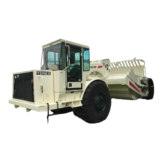
T S1 4 G
Ove rhung Sc ra pe r
M a int e na nc e M a nua l
CLICK HERE TO RETURN TO
MAIN LIBRARY INDEX
TECHNICAL PUBLICATIONS DEPARTMENT
TEREX EQUIPMENT LIMITED,
MOTHERWELL, SCOTLAND, ML1 5RY
PART No. 15501198
REF. NO. 853
SM 2283 Rev 1 12-05
Courtesy of Machine.Market
Advertisement
Table of Contents

Related Manuals for Terex TS14G

Summary of Contents for Terex TS14G
- Page 1 M a int e na nc e M a nua l CLICK HERE TO RETURN TO MAIN LIBRARY INDEX TECHNICAL PUBLICATIONS DEPARTMENT TEREX EQUIPMENT LIMITED, MOTHERWELL, SCOTLAND, ML1 5RY PART No. 15501198 REF. NO. 853 SM 2283 Rev 1 12-05...
- Page 2 Courtesy of Machine.Market...
- Page 3 TEREX SERVICE DEPARTMENT TEREX SERVICE DEPARTMENT TEREX SERVICE DEPARTMENT TEREX SERVICE DEPARTMENT TEREX Equipment Limited, Motherwell, Scotland ML1 5RY Tel. (0698) 732121 Tlx. 77141 Fax. (0698) 734046 TEREX Division, Tulsa, Oklahoma, 74107 USA Tel. (918) 446-5581 Fax. (918) 446-9752 Courtesy of Machine.Market...
- Page 4 THIS PAGE IS INTENTIONALLY LEFT BLANK Courtesy of Machine.Market...
-
Page 5: Important Safety Notice
IMPORTANT SAFETY NOTICE Proper service and repair is important to the safe, reliable operation of all motor vehicles. The service procedures recommended and described in this publication, are effective methods for performing service operations. Some of these service operations require the use of tools specially designed for the purpose. The special tools should be used when, and as recommended. - Page 6 THIS PAGE IS INTENTIONALLY LEFT BLANK Courtesy of Machine.Market...
-
Page 7: Table Of Contents
TABLE OF CONTENTS Section No. Description SM No. GENERAL INFORMATION 0000 TS14G Technical Data 2275 0010 Welding procedure 2172 CHASSIS 0010 Chassis, Hood and Fenders - Tractor 1885 Rev 1 0130 Steering Trunnion - Tractor 1695 ENGINE 0030 Engine and Mounting... - Page 8 TABLE OF CONTENTS Section No. Description SM No. BOWL HYDRAULIC SYSTEM 0000 Hydraulic System Schematic 1893 Rev 1 0010 Hydraulic Lines and Fittings 1894 0020 Bowl Cylinder 2280 0030 Ejector Cylinder 1895 0035 Apron Cylinder 1896 0040 Hydraulic Tank - Tractor 2279 0050 Triple Pump...
-
Page 9: General Information
GENERAL INFORMATION - TS14G Technical Data Section 000-0000 SM - 3151 3 440 (11-3.5) Max. Width 3 060 3 060 (10-0.5) (10-0.5) 2 260 2 260 (7-5) (7-5) 1 460 1 460 (4-9.5) (4-9.5) 3 150 (10-4) to ground 3 810... - Page 10 General Information - TS14G Technical Data Section 000-0000 BRAKES Maximum Torque Full air operated drum brakes with automatic at 1 600 rev/min ......720 Nm (531 lbf ft) application on loss of air pressure. Secondary system Number of cylinders/configuration ....6, Inline can also be manually applied.
- Page 11 General Information - TS14G Technical Data Section 000-0000 ELECTRICAL SYSTEM Servo Control Functions: Type ........24 volt, Negative Ground. Capacity at 2 200 rev/min ......43 litre/min (11.3 US gal/min) Battery ........ Two, 12 Volt, 165 Ah each Accessories ............24 Volt System Pressure at 1 500 rev/min ......
- Page 12 Courtesy of Machine.Market...
-
Page 13: Welding Procedure
GENERAL INFORMATION - Welding Procedure Section 000-0010 Welding WARNING Welding and flame cutting cadmium plated WARNINGS metals produce odourless fumes which are Before any welding is done on a machine toxic. Recommended industrial hygiene equipped with any electronic systems, practice for protection of the welding operator disconnect the following (if applicable) in this from the cadmium fumes and metallic oxides order: Battery earth cable, battery supply... - Page 14 General Information - Welding Procedure Section 000-0010 3. Pre-heat area to 100° C (212° F), measured 3 - 4" 3 - 4" either side of repair prior to gouging. On either side of repair. Avoid local overheating. completion of gouging grind to remove thin carbon layer.
-
Page 15: Chassis
CHASSIS - Chassis, Hood and Fenders Section 100-0010 SM - 3162 27 LH STEP 28 RH STEP 21 30 16 31 21 25 - Bolt 1 - Frame Assembly 17 - Locknut 9 - Bolt 18 - Step Assembly 26 - Hardened 2 - Spindle Assembly 10 - Washer 19 - Cover... -
Page 16: Engine
Chassis - Chassis, Hood and Fenders Section 100-0010 2. Block all road wheels and place battery master SM - 3163 switch in the 'Off' position. 3. Attach a suitable lifting device to the component and remove mounting hardware. Remove the component from the vehicle. - Page 17 Chassis - Chassis, Hood and Fenders Section 100-0010 SM - 2093 12 13 7 9 8 6 STEP BRACKET 6 - Retainer 1 - LH Fender Assembly 11 - Bolt 7 - Screw 2 - Step Assembly 12 - Lockwasher 3 - Bolt 8 - Lockwasher 13 - Nut...
- Page 18 Chassis - Chassis, Hood and Fenders Section 100-0010 Oil Transfer Tube 9. Pre-heat the weld joint to 149 - 205° C 1. Burn off weld that fastens oil transfer tube to (360 - 400° F) and maintain the heat during the spindle.
- Page 19 Chassis - Chassis, Hood and Fenders Section 100-0010 SM - 2209 7 - Shaft 1 - Spindle 3 - Banjo 5 - Washer 8 - Sleeve 2 - Banjo Outer Plate 4 - Nut 6 - Pilot 9 - Fixture Fig.
- Page 20 INCHES 0.0004 0.010 0.002 0.05 0.153 3.89 0.213 5.41 0.50 12.7 0.656 16.66 0.75 19.05 1.50 3.81 1.625 41.28 1.81 46.0 1.88 47.8 1.994 50.65 50.8 2.001 50.83 2.003 50.88 2.249 57.12 2.251 57.18 2.252 57.20 2.256 57.30 2.75 69.9 3.00 7.60 3.182...
- Page 21 Chassis - Chassis, Hood and Fenders Section 100-0010 MAINTENANCE Note: Prior to welding, switch off/disconnect the following in the order given. Failure to do so may Inspection seriously damage the machines electrical components. Inspect the frame and attached parts at intervals not exceeding 250 hours for cracked or broken welds and a - Turn ignition keyswitch off bending/twisting of the frame.
- Page 22 Chassis - Chassis, Hood and Fenders Section 100-0010 Painting If painting of the actual frame of the unit is required, A check of the condition of the paint should be made thoroughly clean the areas to be painted. Apply a approximately twice a year and chassis repainted if primer coat of red oxide and then a finish coat of necessary.
- Page 23 CHASSIS - Steering Trunnion Section 100-0130 SM - 2256 1 - Steering Trunnion 9 - Lockwasher 13 - Pin 5 - Washer 14 - Bolt 2 - Bushing 6 - Pin 10 - Bolt 3 - Washer 11 - Stop Block 15 - Lockwasher 7 - Lube Fitting 4 - Washer...
-
Page 24: Installation And Assembly
Chassis - Steering Trunnion Section 100-0130 4. Separate scraper from tractor. Refer to 1. If removed, install bushing (2) in steering trunnion (1). Section 280-0020, PULL YOKE. 2. If removed, position washer (3) on steering trunnion 5. Remove steering cylinders. Refer to (1) and weld as shown in Fig. - Page 25 Chassis - Steering Trunnion Section 100-0130 SM - 2201 WASHER REF. 3 FIG. 1 1.30-60˚ BUSHING REF. 2 FIG. 1 STEERING TRUNNION REF. 1 FIG. 1 Fig. 2 - Washer and Bushing Installation SM 1695 2-99 Courtesy of Machine.Market...
- Page 26 Courtesy of Machine.Market...
-
Page 27: Engine And Mounting
Engine - Engine and Mounting Section 110-0030 SM - 3150 REMOTE MOUNTED FUEL FILTER LUBE 15,17 7 LH 8 RH 15 RH 16 LH 13 - Locknut 19 - Bracket 7 - Rear LH Mount 1 - Engine 14 - Bolt 20 - Lockwasher 8 - Rear RH Mount 2 - Oil Filter... - Page 28 Engine - Engine and Mounting Section 110-0030 SM - 3152 IN-LINE FILTER S.W.E. FILTER AND FILTER LINES S.W.E. Fig. 2 - Remote & in-line Fuel filter connection lines. correct fuel output and timing for optimum power, fuel QUANTUM ELECTRONIC FUEL SYSTEM economy and emissions.
- Page 29 Engine - Engine and Mounting Section 110-0030 SM - 3149 STOP 6 - Stop Engine Light 1 - Electronic Control Module (ECM) 2 - Programmable Read Only Memory PROM) 7 - Check Engine Light 3 - Electronic Fuel System Injectors 8 - Diagnostic Switch 9 - Diagnostic Request Switch 4 - Batteries...
- Page 30 Engine - Engine and Mounting Section 110-0030 If any gauge operates outwith its normal operating Operation range or a warning light illuminates, shut engine down immediately and report to service or maintenance When the 'Stop' light on the dash panel illuminates, the personnel.
- Page 31 Engine - Engine and Mounting Section 110-0030 If no active fault codes are recorded, both ('Stop' & 'Check') lights will come on and stay on. If active codes are recorded, both lights will come on momentarily. The amber ('Check') and red ('Stop') lights will begin to flash the code of the recorded fault.
- Page 32 Engine - Engine and Mounting Section 110-0030 ELECTRONIC FUEL SYSTEM DIAGNOSTIC CODES Error Code Description Fault Lamp ECM Hardware Internal Failure - Mission Disabling Engine Speed Sensor- Both signals lost Boost Pressure Sensor- Component shorted high Amber Boost Pressure Sensor - Component shorted low Amber Throttle Position Sensor- Component shorted high Throttle Position Sensor - Component shorted low...
- Page 33 Engine - Engine and Mounting Section 110-0030 ELECTRONIC FUEL SYSTEM DIAGNOSTIC CODES Error Code Description Fault Lamp Engine coolant Level Sensor Singals - Data invlaid Amber Water In Fuel Sensor - Circuit shorted low Amber Accelerator Pedal Idle Validation Circuit - Data uncorrect Amber Accelerator Pedal Idle Validation Circuit - Out of calibration Intake manifold Pressure Sensor - Circuit data incorrect...
-
Page 34: Air Cleaner
Engine - Engine and Mounting Section 110-0030 REMOVAL clamp at air cleaner intake pipe and draw air cleaner, complete with rubber hose, away from intake pipe. Tractor Disconnect air cleaner intake pipe and remove from the engine. Cover open ends to prevent entry of dirt. Numbers in parentheses refer to Fig. -
Page 35: Power Takeoff - Tractor
Engine - Engine and Mounting Section 110-0030 5. Remove mounting hardware securing dipstick 18. Disconnect driveline from the engine coupling and assembly to engine (1). Remove dipstick assembly secure clear of the engine. Refer to Section 130-0010, from engine (1). DRIVELINE. - Page 36 Engine - Engine and Mounting Section 110-0030 flywheel and coupling. Apply Loctite retaining 2. Secure engine (1) assembly to frame mounting compound to coupling face. brackets with bolts (10 & 14), snubbing washers (11) washers (12) and locknuts (13) as shown in Fig. 1. b.
- Page 37 Engine - Engine and Mounting Section 110-0030 16. Ensure all lines, harnesses and cables are secured Engine (1) Oil Level Check - Position the vehicle on a with clips and clamps as removed during removal. level work area, apply the parking brake, shut off the Ensure no lines are chaffing on sharp edges or resting engine and wait at least five minutes (to allow oil to against areas where heat will be evident.
- Page 38 Engine - Engine and Mounting Section 110-0030 4. Start a new oil filter (2) on the filter adaptor and 1. Close shut off valves at coolant filter (3) inlet and tighten it by hand until the seal touches the adaptor outlet lines and, using filter wrench, remove and filter head.
- Page 39 Engine - Engine and Mounting Section 110-0030 SPECIAL TOOLS SM - 2055 Refer to Section 300-0070, SERVICE TOOLS, for part 0.10 numbers of service tools which should be used in conjunction with procedures outlined in the engine 0.05 manufacturers service manual, and, general service + 0.000 ø...
- Page 40 Courtesy of Machine.Market...
- Page 41 ENGINE - Air Cleaner Section 110-0050 SM - 1532 1 - Air Cleaner Body 2 - Primary Element 3 - Safety Element 4 - Cover Assembly 5 - Latch 6 - Vacuator Valve Fig. 1 - Exploded View of Air Cleaner DESCRIPTION A mechanical air restriction gauge (12, Fig.
- Page 42 Engine - Air Cleaner Section 110-0050 SM - 2097 1 - Bracket Assembly 11 - Lockwasher 6 - Clamp 16 - Nut 2 - Elbow 12 - Air Restriction Gauge 7 - Mounting Band 17 - Bolt 3 - Elbow 8 - Rod 13 - Cap Assembly 18 - Washer...
- Page 43 Engine - Air Cleaner Section 110-0050 3. Slacken clamp (6, Fig. 2) and disconnect elbow 4. If the major contaminant on primary element (2) is light dust, direct a jet of compressed air, not exceeding (3, Fig. 2) from air cleaner body (1). 6.9 bar (100 lbf/in ), against the pleats of the element.
- Page 44 Engine - Air Cleaner Section 110-0050 Secondary Element The recommended maximum allowable intake Numbers in parentheses refer to Fig. 1. restrictions at rated speed and load are as follows: Since safety element (3) is protected from a. 380 mm-H O (15 in-H O) with clean filter elements.
-
Page 45: Bowl Hydraulic System
ENGINE - Power Takeoff - Tractor Section 110-0130 SM - 3164 11 12 8,24 1 - Oil Seal 10 - PTO Cover 19 - Oil Seal 29 - Bearing 2 - Flywheel Cover Case 11 - Breather Cap 20 - Spacer 30 - Plug 3 - Bolt 12 - Coupling... - Page 46 Engine - Power Takeoff - Tractor Section 110-0130 drain plug (30) from PTO cover (10). Reinstall drain 8. If necessary, note locations and remove dowel pins plug (30) securely. (25) from flywheel cover case (2) and breather assembly (11, 12, 13 & 14) from PTO cover (10). 5.
- Page 47 Engine - Power Takeoff - Tractor Section 110-0130 2. Install new oil seal (1) in centre bore of flywheel 2. Using suitable lifting equipment, position triple pump cover case (2) so that it is flush with flywheel cover over its mounting studs and secure with nuts and case (2) face.
- Page 48 Engine - Power Takeoff - Tractor Section 110-0130 SPECIAL TORQUE SPECIFICATIONS TORQUE FIG. NO. ITEM NO. ITEM NAME lbf ft Bolt 54 - 60 40 - 44 Locknut 950 - 1 085 700 - 800 SM 1693 Rev1 03-04 Courtesy of Machine.Market...
- Page 49 ENGINE - Flywheel Cover Group - Scraper Section 110-0130 SM - 2203 1 - Spacer 6 - Snap Ring 11 - Oil Seal 16 - Cotter Pin 2 - Flywheel Cover Case 7 - Snap Ring 12 - Lockwasher 17 - Grease Fitting 3 - Driveshaft 8 - Bearing 13 - Bolt...
- Page 50 Engine - Flywheel Cover Group - Scraper Section 110-0130 DISASSEMBLY ASSEMBLY Numbers in parentheses refer to Fig. 1. Numbers in parentheses refer to Fig. 1. 1. Remove cotter pin (16), slotted nut (15) and washer Note: Prior to assembly, lubricate all seal lips and (14) from driveshaft (3).
- Page 51 Engine - Flywheel Cover Group - Scraper Section 110-0130 INSTALLATION in Section 300-0020, LUBRICATION SYSTEM. Do Numbers in parentheses refer to Fig. 1. NOT overgrease. Note: When reassembling flywheel cover assembly to 4. Place the battery master switch in the 'On' position, start the engine and bring oil to correct operating engine flywheel housing, be sure to align match marks inscribed during disassembly.
- Page 52 Courtesy of Machine.Market...
-
Page 53: Transmission Electronic Controls
TRANSMISSION - Transmission and Mounting Section 120-0010 SM - 2199 1 - LH Bracket Assembly 5 - Bolt 2 - RH Bracket Assembly 6 - Isolation Mount 9 - Bolt 3 - Bolt 7 - Spacer 10 - Hardened Washer 4 - Lockwasher 8 - Snubbing Washer 11 - Locknut... -
Page 54: Driveline
Transmission - Transmission and Mounting Section 120-0010 REMOVAL 7. Remove air tanks and mounting bracket from the machine. Refer to Section 250-0170, AIR TANKS AND Numbers in parentheses refer to Fig. 1. MOUNTING. Note: Tag all lines, cables and linkages disconnected 8. - Page 55 Transmission - Transmission and Mounting Section 120-0010 SM - 2200 TRANSMISSION OIL COOLER 1 - Hose Assembly 6 - Adaptor 2 - Hose Assembly 11 - Elbow - 90° 7 - Elbow - 90° 3 - Hose Assembly 12 - Tee Piece 8 - Adaptor 13 - Oil Filter Head 4 - Hose Assembly...
- Page 56 Transmission - Transmission and Mounting Section 120-0010 INSPECTION Note: Tighten all hydraulic lines fitted with ORFS Numbers in parentheses refer to Fig. 1. connections, as described in Section 220-0000, STEERING SYSTEM SCHEMATIC. Renew all 'O' rings 1. Check LH bracket assembly (1), RH bracket where used.
- Page 57 Transmission - Transmission and Mounting Section 120-0010 Oil Level Check 9. Connect driveline to the transmission and secure with mounting hardware removed during removal. Refer to Section 130-0010, DRIVELINE. WARNING 10. Install air tanks and mounting bracket to the When checking the oil level, be sure that the machine.
- Page 58 Transmission - Transmission and Mounting Section 120-0010 changed every 1 000 hours, or sooner, depending on At each oil change, examine the used oil for evidence operating conditions. Clean oil filter head (13, Fig. 2) of dirt or water. A normal amount of condensation will when changing filter cartridges (14, Fig.
- Page 59 TRANSMISSION - Transmission Electronic Controls Section 120-0070 DESCRIPTION The transmission uses electrohydraulic valves to This machine is fitted with a Funk DF158 Powershift control the operation of the transmission. The transmission equipped with the Funk DF158 Electronic solenoids controlling the transmission clutches Control Unit (ECU), to operate the transmission.
- Page 60 Transmission - Transmission Electronic Controls Section 120-0070 4. Transmission Output Speed MPU - The 7. Gear/Diagnostic Display Unit - A dash mounted transmission output speed MPU is located in the rear gear/diagnostic display unit provides the operator with housing of the transmission and provides a signal to information about the system.
- Page 61 Transmission - Transmission Electronic Controls Section 120-0070 POWERSHIFT TROUBLESHOOTING Symptom Problem Solution Low oil level. Add oil to proper level. Erratic oil pressure. Suction tube fitting. Replace 'O' ring fitting. Suction manifold 'O' ring not sealing. Replace 'O' ring. Foreign object in suction port. Remove object and check for other contamination.
- Page 62 Transmission - Transmission Electronic Controls Section 120-0070 POWERSHIFT TROUBLESHOOTING - Continued Symptom Problem Solution Converter bypass valve defective. Replace converter bypass valve. Low or no converter pressure (Converter in pressure). Converter hub seal ring not sealing. Replace seal ring. Check converter offset dimension. Correct offset dimension.
- Page 63 Transmission - Transmission Electronic Controls Section 120-0070 POWERSHIFT TROUBLESHOOTING - Continued Symptom Problem Solution Low or no converter pressure. Converter bypass valve defective. Replace converter bypass valve. Transmission pressure checks Converter sprag clutch damaged or Disassemble and inspect converter. installed wrong. okay, but has no power and possibly overheating.
- Page 64 Transmission - Transmission Electronic Controls Section 120-0070 BATTERY REAR + 24V Fuses 15 Amp +24 Out J2-F2 +24 IN +24 IN Slave Rear J2-C3 +24 OUT R/S RETURN Calibrate Rear J2-C2 RUN / START MODULE +24 OUT Slave Front START/RUN START Calibrate Front Switch...
- Page 65 Transmission - Transmission Electronic Controls Section 120-0070 SM - 1779 SM - 1780 S5 T9 J4 T12 S1 S3 S16A TRANSMISSION EXTENSION S5 - To Digital Display J4 - To Gear Shift Selector S6 - Diagnostic Connector J5 - Jumper to Scraper S8 - To Vehicle Electronics ECU Harness (J5A) S16 - Calibration Connector...
- Page 66 Transmission - Transmission Electronic Controls Section 120-0070 Diagnostic code: 32 Diagnostic code: 42 Error type: Driver 3 cannot get down to requested Error type: Bottom of Clutch input on J1-K2 is current. passive. Error: Short or positive in Solenoid 3 circuit from Error: Application does not utilize inching.
- Page 67 Transmission - Transmission Electronic Controls Section 120-0070 Diagnostic code: 50 Diagnostic code: 84 Error: Illegal or undefined vehicle mode code. Error: UPSHIFT (input pin J1-H2) and DOWNSHIFT (input pin J1-H3) are both active at ECU. Diagnostic code: 85 Error: PARK (input pin J2-B3) is active but NEUTRAL Diagnostic code: 51 (input pin J2-A1) is passive at ECU.
- Page 68 Transmission - Transmission Electronic Controls Section 120-0070 Diagnostic code: 97 Diagnostic code: 112 Error: Upper cab mode selected but FORWARD, Error: Clutch 4 fast fill time exceeds 300 ms. NEUTRAL and REVERSE inputs are all passive at ECU. Diagnostic code: 113 Error: Clutch A fast fill time exceeds 300 ms.
- Page 69 Transmission - Transmission Electronic Controls Section 120-0070 Diagnostic code: 149 Diagnostic code: 173 Error: Vehicle system voltage (J3-A1) is too high. Error: Group three enable high should be low. Diagnostic code: 150 Diagnostic code: 174 Error: Transmission temperature (J1-C3) is too high. Error: EEprom check sum error.
- Page 70 Transmission - Transmission Electronic Controls Section 120-0070 GLOSSARY lntershift Pause Time: The minimum time delay Analog: A signal which has a continuous range of between shifts. A value preprogrammed into the ECU. possible voltages. Neutral Recoverable: The process where a detected Active: The high voltage (+12V / +24V) state of a fault is maintained and displayed by the ECU until the digital input.
- Page 71 Transmission - Transmission Electronic Controls Section 120-0070 ABBREVIATIONS USED IN ECU GROUP DC: Direct Current ECU: Electronic Control Unit TOC: Top of Clutch PMW: Pulse Width Modulated BOC: Bottom of Clutch MPU: Magnetic Pickup Sensor V: Volt GND: Ground CYL: Cylinder RPM: Revolutions Per Minute ENG: Engine REV: Reverse...
- Page 72 Courtesy of Machine.Market...
- Page 73 DRIVELINES - Front and Rear Drivelines Section 130-0010 SM- 3167 ENGINE FRONT AXLE 1 - Front Driveline Assembly 10 - Guard 6- Universal Joint 2 - Universal Joint 7 - Bolt 11 - Guard 3 - Bolt 8 - Bolt 12 - Bolt 4 - Bolt 13 - Lockwasher...
- Page 74 Drivelines - Front and Rear Drivelines Section 130-0010 SM - 3165 1 - Driveline Assembly 4 - Bolt 7 - Bolt 2 - Universal Joint 8 - Lockwasher 5 - Guard 3 - Bolt 6 - Guard 9 - Washer Fig.
- Page 75 Drivelines - Front and Rear Drivelines Section 130-0010 AXLE TRANSMISSION 1 - Driveline Assembly 4 - Bolt 2 - Universal Joint 5 - Bolt 3 - Bolt Fig. 4 - Rear Driveline Detail. 1. Position the vehicle in a level work area, apply the 6.
- Page 76 Drivelines - Front and Rear Drivelines Section 130-0010 2. Install universal joint (2) to yoke end of Front DISASSEMBLY driveline assembly (1) and secure with Bolts (3). Universal Joint 3. Place the shaft end of Front driveline assembly (1) Numbers in parentheses refer to Fig. 1, unless stated in a soft jawed vice.
- Page 77 Drivelines - Front and Rear Drivelines Section 130-0010 Periodic Inspection 1. Position Front driveline assembly (1) on the engine Use a small pry bar to check the companion flange end as shown and align match marks on universal yokes for looseness. If loose, drop one end of the joints (2) with those on its mating surfaces.
- Page 78 Drivelines - Front and Rear Drivelines Section 130-0010 DRIVELINE DIAGNOSIS CHART CONDITION REASON REMEDY Vibration or noise Driveline bent or out of balance Clean driveline in a suitable solvent. Inspect for contact with adjacent parts. If driveline is distorted or sprung, replace. If driveline does not run smoothly, and vibration is felt, remove driveline and dynamically balance the assembly.
- Page 79 FRONT AXLE - Differential Section 140-0060 SM - 2175 33 - Yoke Flange 11 - Washer 22 - Bushing 1 - RH Adjuster 12 - Bolt 34 - Seal 23 - LH Adjuster 2 - Bearing Cup 13 - Ring Gear 35 - Outer Cone 24 - Bearing Cup 3 - Bearing Cone...
- Page 80 Front Axle - Differential Section 140-0060 which are bolted to ring gear (13). Thus, ring gear SM - 2176 (13), plain case (4) and flanged case (14) rotate as an assembly when driven by input pinion gear (28). However, side gears (6 & 10), into which each axle shaft is inserted, are free to rotate independently about spider pinion gears (8) with which they are meshed.
- Page 81 Front Axle - Differential Section 140-0060 SM - 2177 SM - 096 Fig. 3 - Removing Differential Assembly from Housing Fig. 4 - Driving Out Pinion Bearing Cage DISASSEMBLY Pinion Cage Group Numbers in parentheses refer to Fig. 1. Note: Before disassembling, punch identifying marks on pinion bearing cage (39) and carrier housing (26) for assembly purposes.
- Page 82 Front Axle - Differential Section 140-0060 hammer. Be careful not to damage the inside SM - 097 machined surface of bearing cage (39) when removing these components. 6. Invert bearing cage (39) in the vice and tap out inner bearing cup (30). Note: If the bearing races are still serviceable, wire the cups and corresponding cones together for proper mating in assembly.
- Page 83 Front Axle - Differential Section 140-0060 advisable to replace side gears (6 & 10) or spider SM - 095 pinion gears (8) in matched sets only, because a newer gear installed to operate in conjunction with an older, worn gear tends to carry an uneven portion of the load.
- Page 84 Front Axle - Differential Section 140-0060 3. Press cone (3) on plain case (4) and press cone SM - 661 (25) on flanged case (14). TAIL BEARING INNER RACE 4. Lubricate inner walls of flanged case (14), plain case (4) and all component parts with gear lubricant. Refer to Section 300-0020, LUBRICATION SYSTEM, for proper lubricant.
- Page 85 Front Axle - Differential Section 140-0060 SM - 2179 SM - 2180 Fig. 9 - Installing Yoke Fig. 10 - Checking Bearing Preload noticable drag or preload on the pinion bearings when If the preload is too much, use a combination of two yoke nut (32) is tightened to the torque specified.
- Page 86 Front Axle - Differential Section 140-0060 Ring Gear Assembly to Carrier Housing SM - 101 Bearing adjusters (1 & 23) have two basic functions: pre-loading bearings (2, 3 & 24, 25); and positioning ring gear (13) to obtain the correct backlash between the ring gear and pinion gear (28).
- Page 87 Front Axle - Differential Section 140-0060 tooth pattern is obtained, make certain that pinion SM - 105 bearing cage bolts (37) are torque tightened to 230 - 260 Nm (170 - 190 lbf ft). Again check backlash tolerance and gear tooth pattern. 15.
- Page 88 Front Axle - Differential Section 140-0060 teeth, see Fig. 15, move the pinion out by adding SM - 108 shims. E. If the contact area is along the top edge of the ring gear teeth, see Fig. 16, move the pinion in by removing shims.
- Page 89 Front Axle - Differential Section 140-0060 7. Install the axle shafts, then install and secure the to no more than 13 mm (1/2 in) below the fill level, driving flange cover to the wheels. Refer to with new lubricant as recommended. Refer to Section 160-0040, PLANETARY GEARING.
- Page 90 Front Axle - Differential Section 140-0060 DIAGNOSIS CHART CONDITION REASON REMEDY Vibration Broken gear teeth Replace damaged gear Excessive run-out of pinion or Disassemble, correct or replace faulty part flanged case Continual noise Bearing worn Replace worn parts Gears damaged or worn Replace gears Noise on drive Ring and pinion gear adjustment tight...
- Page 91 REAR AXLE - Differential Section 160-0020 SM - 2230 1 - RH Adjuster 12 - Bolt 23 - LH Adjuster 34 - Seal 13 - Ring Gear 2 - Bearing Cup 24 - Bearing Cup 35 - Outer Cone 14 - Flanged Case 25 - Bearing Cone 3 - Bearing Cone 36 - Outer Cup...
- Page 92 Rear Axle - Differential Section 160-0020 which are bolted to ring gear (13). Thus, ring gear SM - 2176 (13), plain case (4) and flanged case (14) rotate as an assembly when driven by input pinion gear (28). However, side gears (6 & 10), into which each axle shaft is inserted, are free to rotate independently about spider pinion gears (8) with which they are meshed.
- Page 93 Rear Axle - Differential Section 160-0020 SM - 2177 SM - 096 Fig. 3 - Removing Differential Assembly from Housing Fig. 4 - Driving Out Pinion Bearing Cage DISASSEMBLY Pinion Cage Group Numbers in parentheses refer to Fig. 1. Note: Before disassembling, punch identifying marks on pinion bearing cage (39) and carrier housing (26) for assembly purposes.
-
Page 94: Nospin Element
Rear Axle - Differential Section 160-0020 hammer. Be careful not to damage the inside SM - 097 machined surface of bearing cage (39) when removing these components. 6. Invert bearing cage (39) in the vice and tap out inner bearing cup (30). Note: If the bearing races are still serviceable, wire the cups and corresponding cones together for proper mating in assembly. - Page 95 Rear Axle - Differential Section 160-0020 6. Inspect all gears, pinions and splines for cracked or SM - 095 broken teeth, excessive wear, and pitted or scored surfaces. Repair or replace as necessary. Note: If either ring gear (13) or pinion gear (28) is defective, both gears must be replaced, because they are serviced only as a matched set.
- Page 96 Rear Axle - Differential Section 160-0020 Assembly of Differential and Ring Gear SM - 661 1. Align identification marks that were made during TAIL BEARING INNER RACE 'Disassembly' on ring gear (13) and flanged case (14). 2. Install bolts (1) through ring gear (13) and flanged case (14) and secure with nuts (15).
- Page 97 Rear Axle - Differential Section 160-0020 SM - 2179 SM - 2180 Fig. 9 - Installing Yoke Fig. 10 - Checking Bearing Preload (840 - 1 020 lbf ft). Tighten nut while rotating bearing The pull in Newtons (lbf) as indicated by the scale, cage in both directions to ensure normal bearing multiplied by the cage body radius in metres (inches) contact.
- Page 98 Rear Axle - Differential Section 160-0020 15. Install nut (32) on pinion gear (28) and torque SM - 101 tighten nut to 1 140 - 1 380 Nm (840 - 1 020 lbf ft). 16. Remove wire from shim (40) pack and set shims in place against flange of bearing cage (39).
- Page 99 Rear Axle - Differential Section 160-0020 tolerance, it will be necessary to alter, add or SM - 105 remove, shims (40) between pinion cage assembly (39) and carrier housing (26). 13. The procedures for keeping differential side bearing pre-load, backlash and favourable gear tooth pattern within specifications is strictly a 'try, check, and try again' method.
- Page 100 Rear Axle - Differential Section 160-0020 gear teeth, see Fig. 13, move ring gear away from SM - 108 pinion by turning bearing adjusters equal amounts until the proper bearing pattern is obtained. C. If the contact area is on the outer part of the ring gear teeth, see Fig.
- Page 101 Rear Axle - Differential Section 160-0020 Lubrication 4. Install the lockwashers, stud nuts and bolts on differential assembly and torque tighten to The differential is splash-lubricated with an extreme 300 - 320 Nm (220 - 240 lbf ft). pressure lubricant. The fill-level plug is located on the rear of the banjo housing.
- Page 102 Rear Axle - Differential Section 160-0020 SPECIAL TOOLS and general service tools required. These tools are Refer to Section 300-0070, SERVICE TOOLS, for available from your dealer. part numbers of special tools outlined in this section DIAGNOSIS CHART CONDITION REASON REMEDY Vibration Broken gear teeth...
- Page 103 REAR AXLE - Axle Planetary Gearing Section 160-0040 SM- 3177 6 10 11 - Pin 16 - Gasket 1 - Internal Ring Gear 6 - Washer 12 - 'O' Ring 17 - Cover 2 - Thrust Washer 7 - Snap Ring 3 - Lockwire 8 - Sun Gear 13 - Driving Flange &...
- Page 104 Rear Axle - Axle Planetary Gearing Section 160-0040 Removal and Disassembly SM - 2182 Numbers in parentheses refer to Fig. 1. WARNING Heavy assembly. To prevent personal injury and property damage, be sure lifting device is of sufficient capacity and properly secured to do the job safely.
- Page 105 Rear Axle - Axle Planetary Gearing Section 160-0040 SM - 237 SM - 238 Fig. 4 - Removing Planetary Assembly Fig. 5 - Measuring Dimension 'A' Inspection SM - 239 Numbers in parentheses refer to Fig. 1. Thoroughly clean all the parts with suitable solvent and air dry.
- Page 106 Rear Axle - Axle Planetary Gearing Section 160-0040 banjo housing, pushing the shaft part way into the sure to reinstall any thread protectors (14) which have differential side gear. Mesh the sun gear with ring gear been removed. and pinions. MAINTENANCE 5.
- Page 107 REAR AXLE GROUP - Wheel Rim and Tyre Section 160-0050 SM - 2168 7 - Hardened Washer 13 - Core 1 - Snap Ring 2 - Seal 8 - Bolt 14 - Valve Cap 15 - Flange 3 - Washer 9 - Bearing Cone 10 - Spindle Nut 16 - 'O' Ring...
- Page 108 Rear Axle Group - Wheel Rim and Tyre Section 160-0050 DISMOUNTING TYRE FROM RIM 9. Move the first pry bar around wheel rim, twisting and following with the second pry bar, until the outer tyre Numbers in parentheses refer to Fig. 1, unless otherwise specified.
-
Page 109: Wheel Assembly
Rear Axle Group - Wheel Rim and Tyre Section 160-0050 frame. Extend jack until tyre bead is broken. Continue WARNING around the rim until tyre bead is broken at all points. Never mix components of one manufacturer's 16. Using suitable lifting equipment, remove tyre from rims with those of another. - Page 110 Rear Axle Group - Wheel Rim and Tyre Section 160-0050 2. If removed, install inner flange (15) over wheel (6). SM - 207 3. Lubricate tyre beads and new 'O' ring (16), with a thin solution of vegetable base soap and water. 4.
- Page 111 Rear Axle Group - Wheel Rim and Tyre Section 160-0050 2. Clean bearings in volatile mineral spirits and wipe SM - 2169 dry with a lint free cloth. Lubricate lightly with light oil and spin by hand, to check for wear and roughness. Replace with new bearings if excessively worn, or if operation is rough or noisy.
- Page 112 Rear Axle Group - Wheel Rim and Tyre Section 160-0050 carbon dioxide, or dry ice, freezing of the cup is used, 10. Start the wheel rotating and torque tighten spindle remember to permit the cup and hub to warm to nut (10) to 740 Nm (550 lbf ft).
- Page 113 Rear Axle Group - Wheel Rim and Tyre Section 160-0050 SM - 208 Make sure that paints, lacquers, paint thinners, or similar materials that produce volatile, flammable vapours are not used or stored near the air intake of the compressor that supplies the air for inflating tyres.
- Page 114 Rear Axle Group - Wheel Rim and Tyre Section 160-0050 tyre explosion because it is an inert gas and will not SM - 1040 support combustion inside the tyre. The same tyre inflation pressure used for air inflation should be used for nitrogen inflation. Tyre valves formerly used with air inflation are entirely satisfactory for use with nitrogen gas.
- Page 115 Rear Axle Group - Wheel Rim and Tyre Section 160-0050 2. Re-inflate the tyre using only dry nitrogen gas to SM - 214 4.15 bar (60 lbf/in²) gauge as a minimum, or to bead- seating pressure as a maximum. 3. Adjust to the service inflation pressure required: a.
- Page 116 Rear Axle Group - Wheel Rim and Tyre Section 160-0050 TYRE EXPLOSION HAZARD SM - 218 WARNING AT LEAST AT LEAST 15 m (50 ft) Whenever a machines tyre(s) is (are) exposed 460 m (1 500 lbf ft) to excessive heat such as a machine fire or extremely hot brakes the hazard of a subsequent violent tyre explosion must be recognized.
- Page 117 Rear Axle Group - Wheel Rim and Tyre Section 160-0050 angle of the skive should be no more than sufficient to The valve cores should be checked for leaks. Keep in expel all foreign material and should extend no deeper mind that valve cores are delicate mechanisms that than the breaker.
- Page 118 Rear Axle Group - Wheel Rim and Tyre Section 160-0050 contributing factor to the deterioration of rubber Never drop, tumble, or roll rim parts. products. Therefore, tyres that are to be stored must be protected from light, heat, oils, dirt, moisture, and If rim parts are stored outdoors, they should be given a ozone.
- Page 119 Rear Axle Group - Wheel Rim and Tyre Section 160-0050 TUBELESS TYRE LEAK DIAGNOSIS Occasionally a tubeless off highway tyre/rim assembly may leak in field service. To determine cause of leakage, the entire assembly including valve hardware, multi-piece rim assembly, 'O' ring and tyre should be checked using a soap solution.
- Page 120 Courtesy of Machine.Market...
- Page 121 REAR AXLE - No SPIN® Element Section 160-0080 SM - 2233 EXTERNAL SPRING INTERNAL SPRING 3 - Spring 1 - Spider & Centre 4 - Spring Retainer Cam Assembly 5 - Side Gear 2 - Driven Clutches & ‘Holdout’ Rings Fig.
- Page 122 Rear Axle - No SPIN® Element Section 160-0080 SM - 2183 EXTERNAL SPRING INTERNAL SPRING 3 - Spring 1 - Spider & Centre 4 - Spring Retainer Cam Assembly 5 - Side Gear 2 - Driven Clutches & ‘Holdout’ Rings Fig.
- Page 123 Rear Axle - No SPIN® Element Section 160-0080 SM - 2184 DRIVEN CLUTCH DRIVEN CLUTCH SPRING SPRING SPRING RETAINER SPRING RETAINER SIDE GEAR SIDE GEAR SPIDER CLUTCH TEETH BOTH DRIVEN CLUTCHES AND SPIDER TRAVEL AT SAME SPEED SPIDER Fig. 3 - Straight Forward Driving SM - 2185 DRIVEN CLUTCH DRIVEN CLUTCH...
- Page 124 Rear Axle - No SPIN® Element Section 160-0080 SM - 2186 PROTRUDING TOOTH OR KEY HOLDOUT RING DRIVEN CLUTCH SPIDER AND CENTRE CAM ASSEMBLY Fig. 5 - 'Holdout’ Ring (with cams) Disassembled from Clutch REMOVAL 4. Do not remove the ring gear from differential carrier case unless the ring gear or case are to be replaced or it is necessary for separation of the inner and outer flanged case halves.
- Page 125 Rear Axle - No SPIN® Element Section 160-0080 SM - 2190 SM - 2188 DIFFERENTIAL PLAIN CASE NoSPIN ® ASSEMBLY WING NUT RETAINING BOLT RETAINING RETAINING WASHER WASHER Fig. 9 - Retaining NoSPIN® Element 6. A retaining bolt and washers should be used to keep the NoSPIN®...
- Page 126 Rear Axle - No SPIN® Element Section 160-0080 INSPECTION SM - 2191 Numbers in parentheses refer to Figs. 1 & 2, unless RETAINER BOLT AND WASHER otherwise stated. 1. Inspect the splines on the side gears (5) and clutches, of the driven clutches and ‘holdout’ rings (2).
- Page 127 Rear Axle - No SPIN® Element Section 160-0080 side gear (5), cup side up. Assemble spring retainer SM - 2192 and side gear assembly over spring (3). Install retaining washer and wing nut on retaining bolt and tighten to keep the NoSPIN® assembly intact. If an internal spring (3) is used, position spring over hub of side gear (5) and assemble spring and side gear as an assembly in driven clutch and ‘holdout’...
- Page 128 Rear Axle - No SPIN® Element Section 160-0080 easily performed by following the steps illustrated 4. Rotate both wheels rearward as far as possible below: (they should stop after only a few inches movement). 5. Hold the left wheel firmly against the stop in the WARNING rearward position and rotate the light wheel in the To prevent personal injury and property...
-
Page 129: Slack Adjuster
BRAKE PARTS - Brake Parts - Scraper Section 165-0031 SM - 2172 1 - Snap Ring 10 - Bolt 11 - Roller 18 - Brake Shoe 2 - Camshaft 19 - Bushing 3 - Clevis Pin & Cotter Pin 12 - Return Spring 20 - Anchor Pin 4 - Nut &... - Page 130 Brake Parts - Brake Parts - Scraper Section 165-0031 REMOVAL AND DISASSEMBLY SM - 2173 Numbers in parentheses refer to Figure 1. WARNINGS When servicing wheel brake parts do not create dust by grinding or sanding brake linings or by cleaning wheel brake parts with a dry brush or with compressed air.
- Page 131 Brake Parts - Brake Parts - Scraper Section 165-0031 INSPECTION 8. Clean all rust off face of brake shoes and smooth Numbers in parentheses refer to Fig. 1. down bolt or rivet holes so lining will fit snugly. 9. When installing linings, always replace all linings on an axle to equalise wear and prevent the brakes from WARNING pulling.
- Page 132 Brake Parts - Brake Parts - Scraper Section 165-0031 SM - 2174 Fig. 3 - Combination Brake Lining BRAKE BALANCING Install plugs (18) in linings over screw heads, and The brakes should be balanced prior to final grind plugs flush with linings. reassembly of the relined brake shoes.
- Page 133 Brake Parts - Brake Parts - Scraper Section 165-0031 ADJUSTMENT SM - 2171 Push Rod and Slack Adjuster Angle Numbers in parentheses refer to Fig. 4. Adjustment must be such as to keep brake chamber push rod travel at a minimum while still maintaining the necessary clearance between the brake shoes and brake drum.
- Page 134 Courtesy of Machine.Market...
- Page 135 BRAKE PARTS - Slack Adjuster Section 165-0060 SM - 2170 1 - Slack Adjuster 5 - Spring 9 - Worm Gear 2 - Bearing 6 - Lock 10 - Rivet 3 - Cover 7 - Adjusting Shaft 11 - Worm 4 - Pin 8 - Plug 12 - Plug...
- Page 136 Brake Parts - Slack Adjuster Section 165-0060 wheels to obtain even braking on all wheels. If apply position. Turn until tight, then back off one third adjustment is necessary, refer to Section 165-0031, of a turn (two flats). If new shoes have been installed, BRAKE PARTS for adjustment procedure.
-
Page 137: Electrical System
Electrical System - Circuit Diagrams Section 190-0000 COMPONENT DESIGNATIONS A4 - Radio/Cassette S6 - Trans Oil Press Switch K1 - Starter Relay A5 - Radio/Cassette Speaker S8 - Blower Switch K4 - Dir Ind Flasher Unit S9 - Washer Switch, F B7 - Coolant Level Sender K5 - Air Cond Clutch S10 - Wiper Switch, F... - Page 138 Electrical System - Circuit Diagrams Section 190-0000 TERMINAL DESIGNATIONS IN ACCORDANCE WITH DIN 72 552 L - LEFT, R - RIGHT, F - FRONT, B - BACK CABLES TWISTED TRAILER 30 TURNS / metre DIODE FUSE CONNECTION SCREENED INDICATOR LIGHT RESISTOR CABLES NOTES:...
- Page 139 Electrical System - Circuit Diagrams Section 190-0000 FUSES Location Fuse No. Circuit Current Rating Ignition Sensed Relay Wipers Keyswitch Spare Rear Wash/Wipe Horn, Front Wash/Wipe Spare Lights Switch Main Beam Wiper Park Front and Rear 7.5A Hazards 7.5A Rear Starter Solenoid Reverse System, Cutting Edge Light 7.5A Brake Lights...
- Page 140 Electrical System - Circuit Diagrams Section 190-0000 FUSES Location Fuse No. Circuit Current Rating Rr Frame Fuse Box Rear Engine Ignition Supply L.H rail Power Box Vehicle System supply 100A Alternator Charge System Supply 100A Front Engine Bay Front Grid Heater Supply 125A Rear Engine Bay Rear Grid Heater Supply...
- Page 141 Electrical System - Circuit Diagrams Section 190-0000 SM 2282 Rev1 04-04 Courtesy of Machine.Market...
- Page 142 Electrical System - Circuit Diagrams Section 190-0000 SM 2282 04-04 Courtesy of Machine.Market...
- Page 143 Electrical System - Circuit Diagrams Section 190-0000 SM 2282 Rev1 04-04 Courtesy of Machine.Market...
- Page 144 Electrical System - Circuit Diagrams Section 190-0000 SM 2282 04-04 Courtesy of Machine.Market...
- Page 145 Electrical System - Circuit Diagrams Section 190-0000 SM 2282 Rev1 04-04 Courtesy of Machine.Market...
- Page 146 Electrical System - Circuit Diagrams Section 190-0000 SM 2282 04-04 Courtesy of Machine.Market...
- Page 147 Electrical System - Circuit Diagrams Section 190-0000 SM 2282 Rev1 04-04 Courtesy of Machine.Market...
- Page 148 Electrical System - Circuit Diagrams Section 190-0000 SM 2282 04-04 Courtesy of Machine.Market...
- Page 149 Electrical System - Circuit Diagrams Section 190-0000 SM 2282 Rev1 04-04 Courtesy of Machine.Market...
- Page 150 Electrical System - Circuit Diagrams Section 190-0000 SM 2282 04-04 Courtesy of Machine.Market...
- Page 151 Electrical System - Circuit Diagrams Section 190-0000 SM 2282 Rev1 04-04 Courtesy of Machine.Market...
- Page 152 Electrical System - Circuit Diagrams Section 190-0000 SM 2282 04-04 Courtesy of Machine.Market...
- Page 153 Electrical System - Circuit Diagrams Section 190-0000 SM 2282 Rev1 04-04 Courtesy of Machine.Market...
- Page 154 Electrical System - Circuit Diagrams Section 190-0000 SM 2282 04-04 Courtesy of Machine.Market...
- Page 155 Electrical System - Circuit Diagrams Section 190-0000 SM 2282 Rev1 04-04 Courtesy of Machine.Market...
- Page 156 Courtesy of Machine.Market...
-
Page 157: Fuel System
ELECTRICAL SYSTEM - Switches and Sensors Section 190-0270 SM - 3175 COOLANT SENDER LOW AIR PRESS SW. PRESS.SW. TRANS PARK BRAKE PRESS SW. RADIATOR ENGINE TRANS TRANS PRESS SW. PRESS SENDER STOP LIGHT PRESS SW. TRANS PRESS TEMP SW. TREADLE VALVE START SOLENOID GRID HEATER POWER RELAY... - Page 158 Electrical System - Switches and Sensors Section 190-0270 SM - 3174 COOLANT SENDER ENGINE TRANS TRANS. TEMP. RADIATOR TRANS. SWITCH/SENDER PRESS. SWT. 9 - Engine Coolant Level Sender 7 - Transmission Oil Temperature Sender/Switch 12 - Air Cleaner Restriction Indicator 8 - Transmission Oil Pressure Switch Fig.
-
Page 159: Braking System
Electrical System - Switches and Sensors Section 190-0270 SM - 3173 RPM x100 TRANS TRANS 24 23 21 22 TEMP TEMP SERVICE PRESS STOP STOP 21 - Engine Diagnostic Switch (Scraper) 1 - Tachometer/Hourmeter 11 - Headlight Main Beam Ind/L 22 - Engine Diagnostic Request Switch (Scraper) 12 - Alternator Charging W/L 2 - Transmission Oil Temperature... - Page 160 Electrical System - Switches and Sensors Section 190-0270 Switch (2) - Rear service circuit air pressure falls below 4.1 bar (60 lbf/in²). Air Pressure Gauge (3, Fig. 3) - Indicates air reservoir pressure. During normal operation, the needle in this gauge should be showing in or approaching the centre If the warning light illuminates, stop the machine, apply of the green zone.
-
Page 161: Fuel Tanks, Lines And Mounting
FUEL SYSTEM - Fuel Tanks, Lines and Mounting Section 200-0040 SM - 3159 1 - Fuel Tank 7 - Gasket 19 - Washer 13 - Lockwasher 2 - Filler Cap 8 - Latch Assembly 20 - Padlock 14 - Bolt 3 - Bolt 9 - Drain Plug 21 - Washer (Hardened) - Page 162 Fuel System - Fuel Tanks, Lines and Mounting Section 200-0040 SM - 2218 17 - Locknut 1 - Fuel Tank 8 - Latch Assembly 13 - Lockwasher 18 - Bolt 2 - Filler Cap 9 - Drain Plug 14 - Bolt 19 - Washer 5 - Cover Plate 11 - Locknut...
- Page 163 Fuel System - Fuel Tanks, Lines and Mounting Section 200-0040 SM - 3160 1 - Elbow - 90° 2 - Connector 3 - Clamp 4 - Fuel Line 5 - Fuel Line 13,14,15,16 6 - Drain Cock 7 - Nipple 8 - Bushing - reducer 9 - Elbow - 90°...
- Page 164 Fuel System - Fuel Tanks, Lines and Mounting Section 200-0040 INSTALLATION General Numbers in parentheses refer to Fig. 1 & 2, unless Refill fuel tank (1) at the end of each day's operation to otherwise specified. prevent condensation from contaminating the fuel. Ensure vent hole in filler cap (2) is clear to prevent a vacuum from building up in fuel tank (1).
-
Page 165: Electronic Foot Pedal
FUEL SYSTEM - Electronic Foot Pedal Section 200-0051 SM - 2099 FRONT ENGINE REAR ENGINE ENGINE 29,30 13 12 1 - Pedal Assembly 10 - Linking Bar 27 - Potentiometer 2 - Harness 19 - Bushing 11 - Plate 28 - Screw 20 - Shaft 3 - Bushing 12 - Pin... - Page 166 Fuel System - Electronic Foot Pedal Section 200-0051 REMOVAL INSTALLATION Numbers in parentheses refer to Fig. 1. Numbers in parentheses refer to Fig. 1. Note: Tighten all fasteners to standard torques listed WARNING in Section 300-0080, STANDARD BOLT AND NUT To prevent personal injury and property TORQUE SPECIFICATIONS.
-
Page 167: Cooling System
COOLING SYSTEM - Radiator and Mounting Section 210-0040 SM - 3154 1 - Fan Guard 8 - Bolt 15 - Washer 22 - Stud 2 - Drain Plug 9 - Lockwasher 16 - Tubing 23 - Spring 3 - Bolt 10 - Bracket 17 - Fill Neck Assembly 24 - Washer... - Page 168 Cooling System - Radiator and Mounting Section 210-0040 SM - 3153 TO ENGINE TO ENGINE TO ENGINE TO TRANS OIL COOLER TO TRANS OIL COOLER 15 - Hose Assembly 10 - Adaptor 1 - Tube Assembly 6 - Reducer Hose 16 - Adaptor 11 - Tube Assembly 2 - Tube Assembly...
- Page 169 Cooling System - Radiator and Mounting Section 210-0040 SM - 3155 11,12 8,9,10 11,12 4 - Side Column - RH 10 - Nut 1 - Top Tank 7 - Nut 5 - Core Assembly 2 - Bottom Tank 11 - Bolt 8 - Stud 6 - Gasket 3 - Side Column - LH...
- Page 170 Cooling System - Radiator and Mounting Section 210-0040 lockwashers (9, Fig. 1) and washers (4, Fig. 1). INSPECTION Numbers in parentheses refer to Fig. 3. INSTALLATION 1. Steam clean all parts thoroughly. Numbers in parentheses refer to Fig. 1. 2. Examine core assembly (5) carefully for possible Note: Tighten all fasteners, without special torques damage.
- Page 171 Cooling System - Radiator and Mounting Section 210-0040 equivalent. This material is a free-flowing powder, (3, Fig. 2) over radiator bottom tank connection and inhibited to prevent attack on the cooling system secure with clamp (5, Fig. 2). materials. 5. Install fan guard (1) to radiator shroud (20) and secure with bolts (3), washers (4).
- Page 172 Cooling System - Radiator and Mounting Section 210-0040 6. Liberally brush on to both sides of the radiator core SPECIAL TOOLS an emulsifying cleaner such as 'Gunk', or equivalent, There are no special tools required for procedures and leave to soak for at least 1 hour. outlined in this section.
-
Page 173: Transmission Oil Cooler
COOLING SYSTEM - Transmission Oil Cooler Section 210-0060 SM - 3156 TO ENGINE WATER PUMP FROM RADIATOR BOTTOM TANK TO ENGINE FROM & TO TRANSMISSION TO COOLER 19 - Lockwasher 1 - Heat Exchanger 7 - Elbow 13 - Sleeve 20 - Connector 2 - Cooler Flange 8 - Clamp... - Page 174 Cooling System - Transmission Oil Cooler Section 210-0060 1. Position the vehicle in a level work area, apply the CLEANING AND DISASSEMBLY parking brake and switch off the engine. Operate the Numbers in parentheses refer to Fig. 1. steering in both directions several times to relieve any pressure in the steering system.
-
Page 175: Steering System Schematic
Cooling System - Transmission Oil Cooler Section 210-0060 3. Make up a solution composed of 1/3 muriatic acid and 2/3 water. To each 9.5 litres (2.5 gal) of solution, WARNING add 227 g (0.5 lb) of oxalic acid. To prevent personal injury and property damage, be sure wheel blocks and lifting 4. - Page 176 Courtesy of Machine.Market...
- Page 177 STEERING SYSTEM - Steering Schematic Section 220-0000 DESCRIPTION One section of the pump draws hydraulic oil from the Numbers in parentheses refer to Fig. 1. hydraulic tank (1) then pumps the oil to the steering valve (3) where, depending on the spool position, oil The operation of the steering system is hydrostatic.
- Page 178 Steering System - Steering Schematic Section 220-0000 SM - 2145 2100 2100 1950 RETURN FROM SERVO CONTROL & BOWL DROP VALVES RETURN FROM PILOT VALVE TO TANK BREATHER 1 - Hydraulic Tank 3 - Steering Valve 5 - Flow Reversing Valve 2 - Triple Pump 4 - Double Relief Valve 6 - Steering Cylinders...
- Page 179 Steering System - Steering Schematic Section 220-0000 Double Relief Valve (4) Diagnostic Test Point Refer to Section 220-0130, DOUBLE RELIEF VALVE. The steering system has one diagnostic test point which enables the service engineer to obtain an The double relief valve is mounted to the top face of accurate steering system pressure reading.
- Page 180 Steering System - Steering Schematic Section 220-0000 FILLING AND BLEEDING THE STEERING MAINTENANCE SYSTEM Maintenance instructions, intervals and warnings, in the individual steering and body hydraulic component 1. Fill hydraulic tank to maximum level. Be ready to sections of this manual, should be adhered to at all add oil when the engine is started.
-
Page 181: Steering Lines And Fittings
STEERING SYSTEM - Steering Lines & Fittings Section 220-0010 SM - 3180 1 - Steering Valve 2 - Pump 4 - Double Relief Valve 6 - Left Steering Cylinder 3 - Right Steering Cylinder 5 - Flow Reversing Valve 7 - Hydraulic Tank Fig. -
Page 182: Steering Valve
Steering System - Steering Lines & Fittings Section 220-0010 SM - 2154 4 - Right Cam 1 - Tractor Steering Trunnion 7 - Reversing Mechanism 5 - Flow Reversing Valve 2 - Scraper Pull Yoke 8 - Left Steering Cylinder 6 - Double Relief Valve 3 - Right Steering Cylinder 9 - Left Cam... -
Page 183: Steering Cylinder
Steering System - Steering Lines & Fittings Section 220-0010 SM - 2155 4 - Left Cam 7 - Reversing Mechanism 1 - Tractor Steering Trunnion 2 - Scraper Pull Yoke 5 - Flow Reversing Valve 8 - Right Steering Cylinder 6 - Double Relief Valve 3 - Left Steering Cylinder 9 - Right Cam... -
Page 184: Double Relief Valve
Steering System - Steering Lines & Fittings Section 220-0010 passages which reverse the flow of oil. The reversed Line (E, Fig. 1) is a bleed line for the double relief flow of oil to the left cylinder is as follows: Oil flows into valve (6), and the flow reversing valve (5) is vented to the base of the cylinder (8, Fig. -
Page 185: Flow Reversing Valve
Steering System - Steering Lines & Fittings Section 220-0010 SM - 2156 - STOP BLOCK - USE WELD ROD E-70 PREHEAT 200˚ TO 300˚F 0.25 INCH AS REQUIRED STEERING FRAME KING PIN SECTION 0.50 ˚F ˚C 200˚ TO 300˚ 95˚ TO 150˚ MEASURE WEAR GAP HERE 0.25 0.50... - Page 186 Courtesy of Machine.Market...
- Page 187 STEERING SYSTEM - Steering Valve Section 220-0090 SM - 2149 1 - Seat 29 - 'O' Ring 43 - Plate 15 - Spring 2 - 'O' Ring 16 - Lockwasher 30 - Spring 44 - Shims 31 - Check 45 - Washer 3 - 'O' Ring 17 - Poppet 4 - Cross-over Relief Valve...
- Page 188 Steering System - Steering Valve Section 220-0090 SM - 2150 SECTIONAL VIEW OF CROSS-OVER RELIEF VALVES AND MAIN RELIEF VALVE ASSEMBLIES PORT A PORT B 15 14 PASSAGE B 41 42 40 39 38 PASSAGE A 48 49 INLET PORT RETURN TO TANK 43 - Plate 15 - Spring...
- Page 189 Steering System - Steering Valve Section 220-0090 SPOOL IN POSITION an obstruction or chuck hole will cause one piston rod Numbers in parentheses refer to Fig. 2. in a steering cylinder to move outward and the piston rod in the other steering cylinder to move inward. The Movement of spool (47) inward in the control valve piston rod moving outward creates a void in the causes pressure to increase in the control valve.
- Page 190 Steering System - Steering Valve Section 220-0090 REMOVAL DISASSEMBLY Numbers in parentheses refer to Fig. 1. Numbers in parentheses refer to Fig. 1 & 2. 1. If required, remove fittings from steering valve and WARNINGS identify to aid in assembly. Hydraulic fluid pressure will remain within the system after engine shutdown.
- Page 191 Steering System - Steering Valve Section 220-0090 ASSEMBLY 9. Remove plug (8) and ‘O’ ring (7) from valve body Numbers in parentheses refer to Fig. 1 & 2. (6). Discard ‘O’ ring (7). Note: Lubricate the bore of steering valve body (6) 10.
- Page 192 Steering System - Steering Valve Section 220-0090 13. Check the dimension shown in Fig. 3 with spool in SM - 2151 ‘Neutral and Hold’ position. If the 25.4 mm (1.00 inch) dimension is not obtained, re-check dimensions A and B, Fig. 3, and adjust as required. SPACER 14.
- Page 193 Steering System - Steering Valve Section 220-0090 INSTALLATION ADJUSTING RELIEF VALVE Note: Tighten all fasteners to standard torques listed Numbers in parentheses refer to Figures 2 and 8. in Section 300-0080, STANDARD BOLT AND NUT TORQUE SPECIFICATIONS. Remove plug from gauge port of steering valve and fit a 0 - 207 bar (0 - 3 000 lbf/in ) pressure gauge.
- Page 194 Courtesy of Machine.Market...
- Page 195 STEERING SYSTEM - Steering Cylinder Section 220-0120 SM - 2385 17 18 14 15 3 13 10 11 8 9 7 1 - Cylinder Tube 2 - End Cap 7 - Screw 12 - Wear Ring 17 - Wiper 3 - Piston 8 - Washer 13 - Piston Seal 18 - Nylon Ring...
- Page 196 Steering System - Steering Cylinder Section 220-0120 REMOVAL DISASSEMBLY Numbers in parentheses refer to Fig. 1. Numbers in parentheses refer to Fig. 1. WARNINGS WARNING Turn steering wheel several times in each To prevent personal injury and property direction to relieve any pressure in the damage, be sure lifting equipment is properly system.
- Page 197 Steering System - Steering Cylinder Section 220-0120 INSPECTION 5. Guide end cap (2) assembly onto piston rod (20). Numbers in parentheses refer to Fig. 1 6. Install piston seal (13) and wear ring (12) into 1. Clean all parts of the cylinder with a suitable piston (3) external grooves.
- Page 198 Steering System - Steering Cylinder Section 220-0120 2. Install pin through base end of cylinder tube (1) 8. Place the battery master switch in the 'On' and steering trunnion. Secure pin with bolt, position, start the engine and operate the steering, lockwasher and nut as removed at Removal.
- Page 199 STEERING SYSTEM - Double Relief Valve Section 220-0130 SM - 2137 7 - Poppet 4 - 'O' Ring 1 - Valve Body 8 - 'O' Ring 2 - Cartridge Assembly 5 - Poppet Plug 9 - 'O' Ring 3 - 'O' Ring 6 - Spring 10 - Plug Fig.
- Page 200 Steering System - Double Relief Valve Section 220-0130 Normal Oil Flow SM - 2138 Normally, oil flows from the steering valve through one of the ports and into the double relief valve. It then flows through the valve and directly into the flow reversing valve.
- Page 201 Steering System - Double Relief Valve Section 220-0130 DISASSEMBLY 5. Check condition of valve cartridges (2). Insert a blunt nose drift or punch in cartridge end and depress Numbers in parentheses refer to Fig. 1. piston. 1. If required, remove elbows from double relief valve Note: If piston does not move freely or hangs up, and identify to aid in assembly.
- Page 202 Steering System - Double Relief Valve Section 220-0130 2. Remove blanking caps from hydraulic lines and 5. Check double relief valve and hydraulic line install lines to double relief valve as identified during connections for leaks and tighten as required. removal.
- Page 203 STEERING SYSTEM - Flow Reversing Valve Section 220-0160 SM - 2139 TO ROD END OF RIGHT CYLINDER TO BASE OF RIGHT CYLINDER RIGHT SPOOL LEFT SPOOL TO ROD END OF LEFT CYLINDER TO BASE OF LEFT CYLINDER Fig. 1 - Cutaway View of Typical Flow Reversing Valve DESCRIPTION AND OPERATION OIL FLOW Letters in parentheses refer to Fig.
- Page 204 Steering System - Flow Reversing Valve Section 220-0160 SM - 2140 1 - Valve Body 4 - Plunger Stop Plug 2 - Plunger 5 - 'O' Ring 7 - Plug 3 - 'Seal 8 - Plug 6 - Plunger Stop Plug Fig.
- Page 205 Steering System - Flow Reversing Valve Section 220-0160 2. Place the battery master switch in the 'Off' position SM - 2138 and block all road wheels. 3. Remove double relief valve (2) from the machine. Refer to Section 220-0130, DOUBLE RELIEF VALVE. 4.
- Page 206 Steering System - Flow Reversing Valve Section 220-0160 4. Insert plungers (2) into valve body (1), as marked at 3. Connect the reversing linkage to the eye of the Disassembly. plungers. Note: If the same plungers that were removed from 4.
- Page 207 STEERING SYSTEM - Steering Linkage Section 220-0190 SM - 2152 1 - Bellcrank 7 - Clevis 13 - Link Bolt 8 - Spring Guides 2 - Bushing 14 - Compression Spring 3 - Cotter Pin 9 - Compression Spring 15 - Grease Fitting 10 - Clevis 4 - Clevis Pin 16 - Roller Assembly...
- Page 208 Steering System - Steering Linkage Section 220-0190 REMOVAL AND DISASSEMBLY INSPECTION Numbers in parentheses refer to Fig. 1. Numbers in parentheses refer to Fig. 1. 1. Clean all parts with a suitable solvent and dry with WARNING compressed air. To prevent personal injury and property damage, be sure wheel blocks are properly 2.
- Page 209 BOWL HYDRAULIC SYSTEM - Hydraulic System Schematic Section 235-0000 DESCRIPTION Relief Valve (7) Numbers in parentheses refer to Fig. 1. Refer to Section 235-0120, RELIEF VALVE. The bowl hydraulic, servo control and steering The direct acting relief valve is mounted at the right hydraulic systems are operated by a triple pump.
- Page 210 Bowl Hydraulic System - Hydraulic System Schematic Section 235-0000 SM - 3181 DOWN DOWN EJECT RETURN 1850 EJECT RETURN RAISE LOWER RAISE LOWER STEERING SYSTEM RETURN FROM STEERING VALVE RETURN FROM DOUBLE RELIEF VALVE RETURN FROM FLOW REVERSING VALVE TANK BREATHER 1 - Hydraulic Tank 9 - Bowl Control Valve 12 - Accumulator...
- Page 211 Bowl Hydraulic System - Hydraulic System Schematic Section 235-0000 The main pressure relief valve permits by-passing piston. The charging valve is equipped with a locking hydraulic oil back to the tank (1), should oil pressure feature which, when opened, will allow the precharge exceed 127.5 bar (1 850 lbf/in ).
- Page 212 Bowl Hydraulic System - Hydraulic System Schematic Section 235-0000 Diagnostic Test Point MAINTENANCE The hydraulic system has one diagnostic test point (A) Maintenance instructions, intervals and warnings, in which enables the service engineer to obtain an the individual component sections of this manual, accurate system pressure reading.
- Page 213 BOWL HYDRAULIC SYSTEM - Hydraulic Lines and Fittings Section 235-0010 DESCRIPTION SM - 2382 Refer to Section 235-0000, HYDRAULIC SYSTEM SCHEMATIC for details of hydraulic schematic and a brief description of the individual components shown in the bowl hydraulic and servo control systems. The hydraulic, servo control and steering hydraulic systems are operated by a triple pump.
- Page 214 Bowl Hydraulic System - Hydraulic Lines and Fittings Section 235-0010 TIMING TEST The apron cylinders are actuated by the apron control lever on the servo valve. Oil flows into and out of the As a general field test, the correct operation of the apron cylinders to raise or lower the apron.
- Page 215 Bowl Hydraulic System - Hydraulic Lines and Fittings Section 235-0010 watching the pressure gauge. The maximum reading 3. Remove the acorn nut and one seal washer. on the gauge will indicate the pressure at which the Loosen the jam nut. Turn the adjusting screw valve is opening.
- Page 216 Bowl Hydraulic System - Hydraulic Lines and Fittings Section 235-0010 HYDRAULIC SYSTEM DIAGNOSIS CONDITION REASON REMEDY Scraper Bowl, Apron Insufficient oil pressure. Check pressures as described earlier. or Ejector inoperative Pump is not being driven or receiving. Check pump drive or intake line. or operates too Faulty control valve operation.
- Page 217 BOWL HYDRAULIC SYSTEM - Bowl Cylinder Section 235-0020 SM - 3182 PORT A 9 12 PORT B 6 - Grub Screw 11 - 'O'-Ring 1 - Cylinder Assembly 7 - Wear Ring 12 - Seal 2 - Retainer 3 - Piston Rod 8 - 'O'-Ring 13 - Backup Ring 9 - Seal...
- Page 218 Bowl Hydraulic System - Bowl Cylinder Section 235-0020 SM - 3182 1 - Cylinder Assembly/Body 6 - Grub Screw 11 - 'O'-Ring 2 - Retainer 7 - Wear Ring 12 - Seal 3 - Piston Rod 8 - 'O'-Ring 13 - Backup Ring 4 - Piston 9 - Seal 14 - Bush...
- Page 219 Bowl Hydraulic System - Bowl Cylinder Section 235-0020 2. Operate steering right and left several times to Remove piston (4) from piston rod (3) by unscrewing relieve pressure in the steering system. Block all grub screw (6) from the piston (4). road wheels and place the battery master switch in the 'Off' position.
- Page 220 Bowl Hydraulic System - Bowl Cylinder Section 235-0020 3. Apply Loctite 243 to first two threads of piston (4). Note: Tighten all hydraulic lines fitted with ORFS Screw piston (4) onto the mating end of Piston rod (3) connections, as described in Section 235-0000, and tighten to a torque of 1 356 Nm (1000 Ibf ft).
- Page 221 BOWL HYDRAULIC SYSTEM - Ejector Cylinder Section 235-0030 SM - 2383 6 10 7 11 8 PORT A 5 - Wear Ring 9 - 'O' Ring 1 - Outer Cylinder 6 - Wear Ring Retainer 10 - 'O' Ring 2 - Piston Tube 7 - Rod Seal 11 - Nylon Ring 3 - Retainer...
- Page 222 Bowl Hydraulic System - Ejector Cylinder Section 235-0030 DISASSEMBLY 3. Inspect piston tube (2) for distortion, cracks or Numbers in parentheses refer to Fig. 1. other defects. Replace piston tube (2) if defective area is irreparable. WARNING 4. Discard all scored, deeply scratched or To prevent personal injury and property excessively worn parts and replace with new ones.
- Page 223 Bowl Hydraulic System - Ejector Cylinder Section 235-0030 8. Engage end cap (13) and outer cylinder (1) thread 3. Remove caps from cylinder port and hose end and and screw up fully. Tighten end cap (13) to a torque install new 'O' ring on hose. Install hose to cylinder of 338 - 407 Nm (250 - 300 lbf ft).
- Page 224 Courtesy of Machine.Market...
- Page 225 BOWL HYDRAULIC SYSTEM - Apron Cylinder Section 235-0035 SM - 2384 GROOVE THIS SIDE 1 - Cylinder Body 7 - Piston Seal 13 - 'O' Ring 2 - Piston 8 - Wear Ring 14 - Lock Ring 3 - Piston Rod 9 - 'O' Ring 15 - Back Up Ring 4 - Retainer...
- Page 226 Bowl Hydraulic System - Apron Cylinder Section 235-0035 DISASSEMBLY other signs of damage. Remove ridges, nicks and Numbers in parentheses refer to Figs. 1 & 2. scratches with a fine stone and re-clean. Replace any components which cannot be repaired. 3.
- Page 227 Bowl Hydraulic System - Apron Cylinder Section 235-0035 8. Install locking screw (10) into piston (2) and 2. Attach cylinder base end to bowl assembly with tighten to a torque of 48 Nm (36 lbf ft). Install wear mounting pin. Secure mounting pin with bolt and ring (8) into external groove on piston (2).
- Page 228 Courtesy of Machine.Market...
- Page 229 BOWL HYDRAULIC SYSTEM - Hydraulic Tank Section 235-0040 SM - 2100 1 - Tank Assembly 8 - Access Cover 15 - Tie Rod 22 - Adaptor 2 - Filler Cap 9 - Bolt 16 - Wing Nut 23 - Plug 3 - Gasket 10 - Bolt 17 - Suction Screen...
- Page 230 Bowl Hydraulic System - Hydraulic Tank Section 235-0040 Checking Oil Level WARNING 1. Operate the bowl hydraulic and steering systems Splashing liquid. Wear a suitable face shield several times to bring the oil to correct operating temperature. when using compressed air to dry hydraulic tank and components.
- Page 231 Bowl Hydraulic System - Hydraulic Tank Section 235-0040 4. With a suitable container in position, remove drain 2. Block all road wheels and place the battery master plug (23), and drain hydraulic oil to below the level of switch in the 'Off' position. suction screens (17).
- Page 232 Bowl Hydraulic System - Hydraulic Tank Section 235-0040 Installation filler cap (2) on filler neck assembly. Note: Tighten all fasteners to standard torques listed in 5. Place the battery master switch in the 'On' Section 300-0080, STANDARD BOLT AND NUT position, remove wheel blocks, start the engine and TORQUE SPECIFICATIONS.
- Page 233 BOWL HYDRAULIC SYSTEM - Triple Pump Section 235-0050 SM - 2128 1 - Snap Ring 9 - Bearings 17 - Connecting Shaft 25 - Drive Gear 2 - Spacer 10 - Pocket Seals 18 - Bearing Carrier 26 - Driven Gear 11 - Thrust Plates 27 - Gear Housing 3 - Seal Retainer...
- Page 234 Bowl Hydraulic System - Triple Pump Section 235-0050 SM - 576 SM - 338 DRIVE GEAR TO BOWL HYDRAULIC CIRCUIT STEERING CIRCUIT TO BOWL INLET OUTLET HYDRAULIC CIRCUIT FROM FROM FROM DRIVEN GEAR TANK TANK TANK Fig. 3 - Hydraulic Schematic of Triple Pump Operation Fig.
- Page 235 Bowl Hydraulic System - Triple Pump Section 235-0050 SM - 2129 9 - Bearings 17 - Connecting Shaft 1 - Snap Ring 25 - Drive Gear 10 - Pocket Seals 18 - Bearing Carrier 26 - Driven Gear 2 - Spacer 11 - Thrust Plates 3 - Seal Retainer 19 - Plug...
- Page 236 Bowl Hydraulic System - Triple Pump Section 235-0050 3. Tap end cover (28) with a soft hammer and SM - 344 separate from gear housing (27). If end cover (28) must be pried off, use care to avoid damaging machined surfaces of the cover and housing. See Fig.
- Page 237 Bowl Hydraulic System - Triple Pump Section 235-0050 8. Repeat Steps 4 through 7 to remove gear housing SM - 348 (22), matched gear set (20 & 21), bearing carrier (18) and connecting shaft (17). 9. Separate and lift off gear housing (15) with care. See Fig.
- Page 238 Bowl Hydraulic System - Triple Pump Section 235-0050 and gear hubs wear, the housing gear bores wear. SM - 354 Excessive bore cutout, particularly in a short period, indicates excessive pump loading or dirty oil. Place a straight edge across the cutout area of the gear bore. If a 0.13 mm (0.005 in) feeler gauge can be slipped between the straight edge and the worn area of the gear bore, replace the gear housing.
- Page 239 Bowl Hydraulic System - Triple Pump Section 235-0050 11. Clean parts in a suitable solvent and dry with SM - 357 compressed air after smoothing surfaces. ASSEMBLY Numbers in parentheses refer to Fig. 6. Note: Tighten all fasteners without special torques specified to standard torques listed in Section 300-0080, STANDARD BOLT AND NUT TORQUE SPECIFICATIONS.
- Page 240 Bowl Hydraulic System - Triple Pump Section 235-0050 against thrust plate (11). Install matched driven gear SM - 362 (13) hub into its bearing (9) so that the three teeth marked at 'Disassembly' will mesh. See Fig. 26. 8. Coat new seals (14 & 16) with grease and insert them into their grooves in both sides of gear housings (15, 22 &...
- Page 241 Bowl Hydraulic System - Triple Pump Section 235-0050 with match marks made at 'Disassembly' aligned, tap SM - 366 gear housing (27) with a soft hammer until it rests snugly against bearing carrier (24). Refer to Fig. 28. If a new housing is used, make sure the large oil port will be toward the inlet, and the small port toward the outlet side of the pump assembly.
- Page 242 Bowl Hydraulic System - Triple Pump Section 235-0050 4. Fill hydraulic tank to the proper level. Refer to SM - 371 Section 235-0040, HYDRAULIC TANK for correct oil level and, Section 300-0020, LUBRICATION SYSTEM for oil specification. 5. Operate the pump at least two minutes at zero pressure at engine idle speed.
- Page 243 BOWL HYDRAULIC SYSTEM - Bowl Control Valve Section 235-0060 SM - 2374 20 21 23 24 11 12 13 14 27 28 48 47 EJECTOR 65 66 59 58 56 55 APRON BOWL 1 - Plug 19 - Seal Ring 2 - Seal Ring 20 - Spring Retainer 37 - Spring Retainer...
- Page 244 Bowl Hydraulic System - Bowl Control Valve Section 235-0060 relief valve (5), three check valve assemblies cylinders which raises the apron. Oil forced out of the (18 to 28) and valve housing (3). apron cylinder rod ends flows into the control valve housing and back into the tank.
- Page 245 Bowl Hydraulic System - Bowl Control Valve Section 235-0060 REMOVAL Control Spool Numbers in parentheses refer to Fig. 1. 1. Clean the entire control valve assembly with a suitable solvent and dry thoroughly. Remove caps from valve housing (3) ports. WARNING 2.
- Page 246 Bowl Hydraulic System - Bowl Control Valve Section 235-0060 adjusting cap (9) and seal ring (8), poppet spring (7) Note: Tighten all fasteners to standard torques listed and poppet (6). in Section 300-0080, STANDARD BOLT AND NUT TORQUE SPECIFICATIONS. 5. Remove plug (1) and seal ring (2) from the opposite end of valve housing (3).
- Page 247 Bowl Hydraulic System - Bowl Control Valve Section 235-0060 ADJUSTMENTS 5. Install spool (61) assembly in valve housing (3) bore. Numbers in parentheses refer to Fig. 1. Relief Valve Adjustment 6. Repeat steps 1 to 5 for the opposite end of spool (61).
- Page 248 Bowl Hydraulic System - Bowl Control Valve Section 235-0060 MAINTENANCE Note: This is a pilot operated relief valve which is sensitive to adjustment. One complete turn of the Relief valve pressure should be checked on a regular adjusting screw will change the pressure setting basis to ensure correct operating pressures are being approximately 55 - 69 bar (800 - 1 000 lbf/in maintained.
- Page 249 BOWL HYDRAULIC SYSTEM - Accumulator Section 235-0070 SM - 277 1 - Charging Valve 8 - Wear Rings 1A - Cap 4 - Protector 1E - Body 9 - 'O' Ring 1B - Core 5 - Piston 10 - End Cap 1F - 'O' Ring 1C - 'O' Ring 2 - Screw...
-
Page 250: Charging The Accumulator
Bowl Hydraulic System - Accumulator Section 235-0070 Testing Pre-charge Pressure SM - 1273 Numbers in parentheses refer to Fig. 2, unless otherwise specified. Note: The nitrogen pressure in an accumulator is directly affected by changes in nitrogen temperature. The cylinder pressure will increase or decrease proportionally with temperature changes. - Page 251 Bowl Hydraulic System - Accumulator Section 235-0070 DISCHARGING NITROGEN WARNINGS Numbers in parentheses refer to Fig. 1, unless Do not use Oxygen or any gas other than otherwise specified. Nitrogen to charge an accumulator. Oxygen under pressure coming into contact with oil or Make sure charging valve (1) is closed internally by turning locknut (1D) clockwise.
- Page 252 Bowl Hydraulic System - Accumulator Section 235-0070 6. Support the accumulator using an adequate sling SM - 2241 and lifting device. Remove nuts (7) and lockwashers (6) securing clamps (2) to mounting positions. Remove accumulator and clamp assemblies (2). DISASSEMBLY Numbers in parentheses refer to Fig.
- Page 253 Bowl Hydraulic System - Accumulator Section 235-0070 oil inlet port downward. otherwise piston will bounce back, damaging the 'V' section ring. 2. Attach clamps (2) securely with lockwashers (6) and nuts (7). 4. Install new 'O' ring (9) on end cap (10) and install end cap (10) in cylinder (12).
- Page 254 Bowl Hydraulic System - Accumulator Section 235-0070 AMBIENT TEMPERATURE - NITROGEN PRE-CHARGE PRESSURE AMBIENT TEMPERATURE NITROGEN PRE-CHARGE PRESSURE °C °F lbf/in² 23.7 24.2 24.8 25.3 25.9 26.4 27.5 28.1 28.6 29.2 29.7 30.5 WARNING This vehicle is equipped with a precharged nitrogen gas cylinder of more than 2.8 bar (40 lbf/in Special permits may be required when transporting the vehicle or cylinder by any method while cylinder is charged.
- Page 255 BOWL HYDRAULIC SYSTEM - Relief Valve Section 235-0120 SM - 2167 11 - Setscrew 1 - Acorn Nut 6 - Seal Ring 12 - Seal Washer 7 - Spring Guide 2 - Seal Washer 13 - Blanking Screw 3 - Jam Nut 8 - Spring 14 - Seal Ring 4 - Adjusting Screw...
- Page 256 Bowl Hydraulic System - Relief Valve Section 235-0120 2. Place the battery master switch in the 'Off' position 7. Remove plug (15) and seal ring (14) from valve and block all road wheels. housing (16). Discard seal ring (14). 3. With suitable containers available to catch spillage, 8.
- Page 257 Bowl Hydraulic System - Relief Valve Section 235-0120 ADJUSTMENTS 5. Install a new seal ring (6) on cap (5) install cap in valve housing (16) and tighten. Numbers in parentheses refer to Fig. 1. Relief Valve Adjustment 6. Fit adjusting screw (4) and screw in until spring (8) is under light compression.
- Page 258 Bowl Hydraulic System - Relief Valve Section 235-0120 MAINTENANCE SERVICE TOOLS Relief valve pressure should be checked on a regular There are no special tools required for the procedures basis to ensure correct operating pressures are being outlined in this section. Refer to Section 300-0070, maintained.
- Page 259 BOWL HYDRAULIC SYSTEM - Servo Control Valve Section 235-0160 SM - 2165 33,34 36,47 38,39 1 - Knob 13 - Lever Plate 25 - Spring Retainer 37 - Spool End 2 - Flexible Cover 14 - Mounting Flange 26 - Spool End 38 - Ball Housing 27 - End Cover 39 - Ball...
- Page 260 Bowl Hydraulic System - Servo Control Valve Section 235-0160 DESCRIPTION REMOVAL The servo control valve is mechanically actuated spool type valve controlling and directing signal oil pressure supplied by the main control valve. The WARNING valve spools are operated by levers connected to the To prevent personal injury and property spool ends.
- Page 261 Bowl Hydraulic System - Servo Control Valve Section 235-0160 SM - 2166 1 - Knob 13 - Lever Plate 25 - Spring Retainer 37 - Spool End 38 - Ball Housing 2 - Flexible Cover 14 - Mounting Flange 26 - Spool End 27 - End Cover 39 - Ball 3 - Lever...
- Page 262 Bowl Hydraulic System - Servo Control Valve Section 235-0160 ASSEMBLY 7. Remove screws (15) from mounting flange (14). Numbers in parentheses refer to Fig. 1 & 2. Remove mounting flange (14) from valve housing (19). Note: Lightly lubricate all components with hydraulic 8.
- Page 263 Bowl Hydraulic System - Servo Control Valve Section 235-0160 INSTALLATION 3. Fill hydraulic oil tank with hydraulic oil as specified in Section 300-0020, LUBRICATION SYSTEM. Refer Numbers in parentheses refer to Figs. 1 & 2. to Section 235-0040, HYDRAULIC TANK, for Note: Tighten all fasteners to standard torques listed hydraulic oil levels.
- Page 264 Courtesy of Machine.Market...
-
Page 265: Air System
BRAKING SYSTEM - Air Braking System Schematic Section 250-0000 DESCRIPTION air horn (13) via the air horn solenoid (12). The air brake system is used to supply air pressure for operating the front and rear brake chambers which in Air compression is controlled by unloader valve on air turn, actuate the slack adjusters applying the front and drier (2) stopping and starting delivery of air from air rear brakes. - Page 266 Braking System - Air Braking System Schematic Section 250-0000 SM - 3183 11 - Quick Release Valve 1 - Air Compressor 6 - Pressure Protection Valve 12 - Air Horn Solenoid 2 - Air Drier Kit 7 - Relay Emergency Valve 13 - Air Horn 3 - Front Primary Tank 8 - Park/Emergency Control Valve...
- Page 267 Braking System - Air Braking System Schematic Section 250-0000 SM - 2227 17 - Rear Primary Tank 21 - Brake Chamber 18 - Rear Secondary Tank 22 - Quick Release Valve 19 - Relay Valve 23 - Drain Cock 20 - Relay Emergency Valve 24 - Test Point Fig.
- Page 268 Braking System - Air Braking System Schematic Section 250-0000 Park/Emergency Control Valve (8) - Controls air c. Park/emergency brake circuit air pressure falls pressure delivery to the relay emergency valve for below 5.5 bar (80 lbf/in actuation of brake chambers to apply the brakes. In the 'PARK' position it exhausts the air from the spring If light illuminates while operating, stop the machine, applied brake chambers, to apply the parking brake.
- Page 269 Braking System - Air Braking System Schematic Section 250-0000 Park/Emergency Brake Control Valve procedures. Some components contain powerful Air line from port '23' of pressure protection valve (6) springs and injury can result if not properly directs a constant supply of air to park/emergency disassembled.
- Page 270 Braking System - Air Braking System Schematic Section 250-0000 Park/Emergency Brake Holding Ability WARNING 1. With the bowl in the 'Fully Raised' position, move If the machine moves during the above checks, park/emergency control lever to 'PARK' position and move transmission gear shift selector to 1st gear. stop the machine, apply the parking brake and do not operate until the fault has been 2.
- Page 271 Braking System - Air Braking System Schematic Section 250-0000 BRAKING SYSTEM DIAGNOSIS (Continued) CONDITION REASON REMEDY Brakes do not apply Defective treadle valve Repair or replace faulty component as with normal treadle recommended in Section 250-0070, TREADLE valve application VALVE. Defective relay emergency valve Repair or replace faulty component as recommended in Section 250-0280, RELAY...
- Page 272 Braking System - Air Braking System Schematic Section 250-0000 BRAKING SYSTEM DIAGNOSIS (Continued) CONDITION REASON REMEDY Air pressure too low Pressure gauge registering Replace gauge and/or gauge sender unit. incorrectly Defective compressor Repair or replace air compressor. Refer to ENGINE MAINTENANCE MANUAL. Excessive leakage.
- Page 273 Braking System - Air Braking System Schematic Section 250-0000 BRAKING SYSTEM DIAGNOSIS (Continued) CONDITION REASON REMEDY Air pressure rises to Worn compressor Repair or replace. Refer to ENGINE normal reading too MAINTENANCE MANUAL. slowly Excessive carbon in compressor Clean the head and lines. Refer to ENGINE cylinder head or discharge line.
- Page 274 Courtesy of Machine.Market...
- Page 275 BRAKING SYSTEM - Treadle Valve Section 250-0070 SM - 3185 22,24 No. 1 DELIVERY PORT No. 1 SUPPLY PORT No. 2 DELIVERY PORT No. 2 SUPPLY PORT EXHAUST 1 - Treadle 12 - Spring 23 - Fulcrum Pin 2 - Spring Seat 13 - Spring 24 - Plunger 3 - Primary Piston...
- Page 276 Braking System - Treadle Valve Section 250-0070 spring seat (2) to the piston (3). Piston (3) moves down circuit, the system is 'Lapped' with inlet valve (10) and its stem, which in turn moves its exhaust seat (4), exhaust passage (32) closed. closing the exhaust passage through exhaust valve (5).
- Page 277 Braking System - Treadle Valve Section 250-0070 1. Position the vehicle in a level work area, apply the 6. Remove wheel blocks from all road wheels. parking brake and switch off the engine. ADJUSTMENTS 2. Operate the steering in both directions several times to relieve any pressure in the steering system.
- Page 278 Courtesy of Machine.Market...
-
Page 279: Operators Compartment
BRAKING SYSTEM - Air Tanks and Mounting Section 250-0170 SM - 3184 DRIER 14 13 1 - Air Tank 13 - Bolt 7 - Locknut 19 - Washer 2 - Clamp Assembly 8 - Bolt 14 - Washer 20 - Tilt Drain Valve 3 - Bracket Assembly 15 - Bracket Assembly 9 - Lockwasher... - Page 280 Braking System - Air Tanks and Mounting Section 250-0170 SM - 2232 1 - Air Tank 4 - Nut 7 - Bolt 2 - Clamp Assembly 5 - Washer 8 - Locknut 3 - Bolt 6 - Bracket Assembly 9 - Washer Fig.
- Page 281 Section 250-0170 using bolts (8) and lockwashers (9). Section 300-0020, STANDARD BOLT AND NUT 8. Using suitable lifting equipment, install air tank (1) in TORQUE SPECIFICATIONS. place on bracket / plate assemblies (3 & 4) and secure to clamp assemblies (2) using bolts (22) and nuts (21). Tractor : Scraper : 1.
- Page 282 Courtesy of Machine.Market...
- Page 283 BRAKING SYSTEM - Quick Release Valve Section 250-0180 DESCRIPTION SM - 2234 There are two quick release valves fitted to the vehicle, one in the tractor lines and the other in the scraper lines. The quick release valves can be identified as items 11 and 21 in Section 250-0000, AIR BRAKING SYSTEM SCHEMATIC.
- Page 284 Braking System - Quick Release Valve Section 250-0180 SM - 2236 SM - 2237 1 - Valve Seat 3 - Exhaust Seat 1 - Valve Seat 3 - Exhaust Seat 2 - Diaphragm 2 - Diaphragm Fig. 3 - Quick Release Valve Operation - Supply Fig.
- Page 285 BRAKING SYSTEM - Park/Emergency Control Valve Section 250-0190 SM - 2240 24 25 DELIVERY AIR PORT SUPPLY AIR PORT EXHAUST PORT 1 - Valve Body 8 - Exhaust Valve 15 - Valve Seat 2 - Adjuster Screw Plate 9 - Exhaust Passage 22 - Valve Cover 16 - Valve Plunger 3 - Adjuster Screw...
- Page 286 Braking System - Park/Emergency Control Valve Section 250-0190 REMOVAL closed. A constant pressure is being maintained in Numbers in parentheses refer to Fig. 1. chamber (18) and in the spring brake chambers. When the control lever (27) is moved against torsion WARNING spring (24) towards the vehicle 'Park' position, the To prevent personal injury and property...
- Page 287 Braking System - Park/Emergency Control Valve Section 250-0190 TESTING exhaust port when the control lever is in the 'Release' Numbers in parentheses refer to Fig. 1. position or 'Park' position. Block all road wheels and ensure air tanks are fully If the valve is found to be leaking, it must be replaced.
- Page 288 Courtesy of Machine.Market...
- Page 289 BRAKING SYSTEM - Air Drier Section 250-0200 SM - 2636 PORT 4 PORT 22 PORT 1 PORT 21 PORT 3 1 - Air Drier 4 - Unloader Valve 7 - Orifice 2 - Air Compressor 5 - Desiccant Cartridge 8 - Purge Tank 3 - Safety Valve 6 - Check Valve Fig.
- Page 290 Braking System - Air Drier Section 250-0200 SM - 2280 1 - Purge Tank 2 - Desiccant 3 - Oil Filter 4 - Unloader Valve 5 - Check Valve A - Supply from Compressor D - Output to Compressor Unloading Device 6 - Purge Choke B - Delivery to Press.
- Page 291 Braking System - Air Drier Section 250-0200 Operation REMOVAL Numbers in parentheses refer to Fig. 1. WARNING When primary tank air pressure under valve (3) exceeds the maximum valve setting of 13 bar To prevent personal injury and property (191 lbf/in²), the valve is forced off its seat, permitting damage, be sure wheel blocks are properly air to escape through exhaust port '3' to atmosphere.
- Page 292 Braking System - Air Drier Section 250-0200 drier unloader valve opens allowing air compressor 4. If water is present, the desiccant cartridge must be output, purge tank air and collected water, dirt and oil replaced and the components in the air drier body to flow out of the drain at the bottom of the air drier.
- Page 293 BRAKING SYSTEM - Brake Chamber Section 250-0260 SM - 2198 12 13 14 15 16 17 7 - Service Brake Diaphragm 1 - Mounting Stud 2 - Push Rod 8 - Clamp Ring 14 - Collar 20 - Release Bolt 15 - Piston 3 - Wiper 9 - Housing...
- Page 294 Braking System - Brake Chamber Section 250-0260 OPERATION Parking Brake Moving the park/emergency brake valve from the Normal Driving 'OFF' position towards the 'PARK' position gradually In its 'OFF' position, the park/emergency brake valve releases the air pressure from the spring brake maintains a constant air pressure on the spring brake chamber and allows the power spring to extend.
- Page 295 Braking System - Brake Chamber Section 250-0260 REMOVAL 1. Install brake chamber on mounting bracket and Numbers in parentheses refer to Fig. 1. secure using mounting hardware as removed at 'Removal'. WARNING 2. Connect clevis assembly to slack adjuster with pin To prevent personal injury and property and cotter pin as removed at 'Removal'.
- Page 296 Braking System - Brake Chamber Section 250-0260 Leak Checking MAINTENANCE Ensure all road wheels are chocked. Detach tube Inspect the brake chambers regularly for any signs of (23) from elbow (22) at the head (19). Apply a soap leakage or damage and repair/replace as required. solution liberally to the service chamber vents, push rod opening, the open end of tube (23), clamp ring (8) Note: Limited repair of the brake chambers is by...
- Page 297 BRAKING SYSTEM - Relay Emergency Valve Section 250-0280 SM - 2258 1 - Valve Body - Upper 7 - Inlet/Exhaust Valve 13 - 'O' Ring 19 - Valve Rubber 2 - 'O' Ring 8 - 'O' Ring 14 - Circlip 20 - Rivet 3 - Piston - Upper 9 - Valve Body - Lower...
- Page 298 Braking System - Relay Emergency Valve Section 250-0280 SM - 2251 SM - 2252 1 - Relay Emergency Valve 1 - Relay Emergency Valve 4 - Adaptor 4 - Adaptor 2 - Locknut 2 - Locknut 5 - Elbow - 90° 5 - Elbow - 90°...
- Page 299 Braking System - Relay Emergency Valve Section 250-0280 REMOVAL/INSTALLATION emergency valve (1) ports as removed from the old Numbers in parentheses refer to Figs. 3 & 4. valve. Note: Tighten all fasteners to standard torques listed 7. Secure relay emergency valve (1) to mounting in Section 300-0080, STANDARD BOLT AND NUT bracket using nuts (3) and lockwashers (2).
- Page 300 Courtesy of Machine.Market...
- Page 301 BRAKING SYSTEM - Relay Valve Section 250-0280 DESCRIPTION SM - 2238 The relay valve can be identified as item 18 in Section 250-0000, AIR BRAKING SYSTEM SCHEMATIC. Mounted off the rear fuel tank right hand mounting bracket, the relay valve is located in the air lines between the treadle valve and rear brake chambers.
- Page 302 Braking System - Relay Valve Section 250-0280 REMOVAL/INSTALLATION (5), reducer (6) and tee piece (7) in new relay valve (1) Numbers in parentheses refer to Fig. 1. ports as removed from the old valve. Note: Tighten all fasteners to standard torques listed 7.
- Page 303 BRAKING SYSTEM - Air Pressure Protection Valve Section 250-0290 DESCRIPTION SM - 3187 The 4 way pressure protection valve can be identified as item 6 in Section 250-0000, AIR BRAKING SYSTEM SCHEMATIC. Mounted off the rear left hand side of the tractor frame, adjacent to the primary air tank, the pressure protection valve is located in the air compressor and air drier delivery line, immediately prior to the air tanks.
- Page 304 Braking System - Air Pressure Protection Valve Section 250-0290 4. Support valve body and remove locknuts (4) and 8. Install air lines and electrical connection to pressure lockwashers (3) securing pressure protection valve (1) protection valve (1), as tagged at 'Removal'. to mounting bracket (2).
- Page 305 AIR SYSTEM - Air Horn Section 255-0020 SM - 2242 1 - Long Projector 2 - Short Projector 3 - Body 4 - Cover 5 - Diaphragms 6 - Screw 7 - Mounting Pad 8 - Mounting Stem 9 - Washer Fig.
- Page 306 Courtesy of Machine.Market...
- Page 307 OPERATORS COMPARTMENT - Cab and Mounting Section 260-0010 SM - 2221 9 - Bolt 10 - Bolt 1 - Rear Cab Support 5 - Bolt 6 - Snubbing Washer 11 - Washer 2 - Front LH Cab Support 12 - Rubber Floor Mat 3 - Front RH Cab Support 7 - Washer 13 - Cab Assembly...
- Page 308 Operators Compartment - Cab and Mounting Section 260-0010 The cab interior, trimmed with noise-absorbant 3. Disconnect the electrical cables in the following material, is extensively thermally insulated and a order to prevent damage to the electrical heater and demisting unit keeps internal air fresh and components.
- Page 309 Operators Compartment - Cab and Mounting Section 260-0010 prevent damage from concentrated loads at cab 5. Remove blanking caps from all bowl hydraulic lifting points with hooks, chains, cables etc.. lines and connect lines as identified at removal. Tighten all lines securely. 12.
- Page 310 Operators Compartment - Cab and Mounting Section 260-0010 14. Ensure parking brake is applied and remove 6. Clean the remains of the adhesive from the edge of wheel blocks from all road wheels. the panel opening using a suitable solvent. 7.
- Page 311 OPERATORS COMPARTMENT - Driver Seat and Mounting Section 260-0090 SM - 2127 1 - Seat Assembly 9 - Height Riser Assembly 17 - Manual Valve 25 - Bolt 10 - Handles 2 - Seat Frame 18 - Bearing 26 - Lockwasher 3 - Latch Height Riser 11 - Height Riser Spring 19 - Lever...
- Page 312 Operator's Compartment - Driver Seat and Mounting Section 260-0090 position to allow easier access. The incorporated block 6. Remove bolts (24 & 25) and lockwashers (26) out maintains the seat in position for driving. securing complete seat assembly to the cab floor. Remove seat assembly from vehicle.
- Page 313 Operator's Compartment - Driver Seat and Mounting Section 260-0090 4. Position lap belt (21) to seat assembly and secure Accumulation of dirt on the surface eventually turns using bolts and lockwashers as removed at Removal. into a hard gritty substance which cuts into the surface of the upholstery.
- Page 314 Courtesy of Machine.Market...
- Page 315 OPERATORS COMPARTMENT - Air Conditioning Section 260-0130 SM - 572 1 - Compressor 3 - Receiver Drier 5 - Evaporator 2 - Condenser 4 - Expansion Valve 6 - Sensing Bulb Fig. 1 - Typical Air Conditioning Flow Diagram DESCRIPTION Compressor Drive Clutch The R-134a compressor systems use an electronically Temperature Control Switch...
- Page 316 Operators Compartment - Air Conditioning Section 260-0130 down this radiation of heat. Cooling fins are located on Thermostatic Expansion Valve the condenser tubes and fans are used to circulate An expansion valve is installed in the system to lower cool air around the condenser tubes. Keep all leaves, the pressure before the R-134a enters the evaporator.
- Page 317 Operators Compartment - Air Conditioning Section 260-0130 Section 100-0010, CHASSIS, HOOD AND FENDERS. REMOVAL 5. Discharge the air conditioning system as described Numbers in parentheses refer to Fig. 2, unless under 'Discharging The System'. otherwise stated. 6. Remove mounting hardware securing cover on air conditioner unit (1) to gain access to refrigerant hosing WARNINGS and control cable (32).
- Page 318 Operators Compartment - Air Conditioning Section 260-0130 SM - 3157 15 16 29 - Water Valve 1 - Air Conditioning Unit 10 - Refrigerant Hose 19 - 'P'-Clip 30 - Lock 2 - Compressor 11 - Spacer (Long) 20 - 'P'-Clip 31 - Fastener 3 - 'O'-Ring 12 - Spacer (Short)
- Page 319 Operators Compartment - Air Conditioning Section 260-0130 SM - 3158 COVER DRAIN 1 - Air Conditioning Unit 41 -Hose (Drain) 36 - Blower Unit 42 - Clamp 37 - Evaporator Matrix 43 - Duct - Flexible 38 - Expansion Valve 44 - Filter Element 39 - Heater Matrix 40 - Clamp...
- Page 320 Operators Compartment - Air Conditioning Section 260-0130 16. Back of Bolts (13) enought to allow gentle pivot 1. If removed, slide air conditioner cover into position motion of compressor unit (2) on outer brackets (35) inside the cab and secure cover with mounting to release tension on 'V' belt (4).
- Page 321 Operators Compartment - Air Conditioning Section 260-0130 12. Install new 'V' belt (4) onto rear groove on engine fan MAINTENANCE pulley and fit to rear groove on compressor (2). 13. Refit Poly 'V' fan belt and adjust tension. Refer to Section 110-0030, ENGINE AND MOUNTING.
- Page 322 Operators Compartment - Air Conditioning Section 260-0130 4. Ensure all hoses and hose clamps are free from 7. A belt that has operated while rolled over in the contact with sharp metal, moving parts or near to sheave groove may be damaged - replace it. manifolds.
- Page 323 Operators Compartment - Air Conditioning Section 260-0130 1. Position the vehicle in a level work area, apply the For New Or Completely Empty System parking brake and switch off the engine. Operate the Note: The charging procedure must be done in ambient steering in both directions several times to relieve any temperatures above 15.5°...
- Page 324 Operators Compartment - Air Conditioning Section 260-0130 Note: Never charge with liquid R-134a. Charge on the Note: Occasionally bubbles are noticed during clutch low pressure side only. cycling or system start-up. This is a normal condition. 5. With the system completely charged, shut off the Final Charging Of The System engine.
- Page 325 Operators Compartment - Air Conditioning Section 260-0130 AIR CONDITIONING DIAGNOSIS CONDITION PROBLEM REMEDY 1. Belt Trouble Slipping Loose Adjust belt to 12 mm (0.5 in) depression Overcharge Correct the charge Air in system Evacuate and re-charge Excessive wear Pulley not aligned Align Pulley Belt too tight Adjust or replace...
- Page 326 Operators Compartment - Air Conditioning Section 260-0130 AIR CONDITIONING DIAGNOSIS (continued) CONDITION PROBLEM REMEDY 3. Noise - Evaporator Rubbing/scraping Fan blade or blower Repair or replace Hissing Low charge/leak Correct charge/repair leak Chatter/Knocking Air in system Evacuate and re-charge Noisy case Loose brackets/screws Tighten Motor squeal...
- Page 327 Operators Compartment - Air Conditioning Section 260-0130 AIR CONDITIONING DIAGNOSIS (continued) CONDITION PROBLEM REMEDY 6. Air Conditioning System Trouble - Gauges must be connected High head pressure Overcharge of refrigerant Purge system as necessary Air in system Correct charge/repair leak Condenser clogged Clean condenser Defective condenser fan motor...
- Page 328 Courtesy of Machine.Market...
-
Page 329: Bowl Cylinder
BODY - SCRAPER BOWL AND TAIL Section 280-0010 SM - 3188 23 24 25 21,22 TRANS. FILTER MTG. CUTTING EDGES 1 - Bowl Assembly 10 - Washer 19 - Grab Handle- Tube 2 - Spindle 11 - Mudflap 20 - Grab Handle- Grip 3 - Bushing 12 - Bolt 21 - Guard... - Page 330 Body - Scraper Bowl and Tail Section 280-0010 becomes an important load-carrying and strengthening SM - 3190 member of the scraper. Bowl The bowl (1) operated by two single stage, double acting cylinders which are pinned to the pull yoke drawbar.
- Page 331 Body - Scraper Bowl and Tail Section 280-0010 3. Remove and discard oil transfer tube from the 7. With a suitable lifting device, position the spindle on spindle. the banjo end plate. 4. Using a grinder, remove all burrs and slag from the 8.
- Page 332 Body - Scraper Bowl and Tail Section 280-0010 SM - 2249 Fig. 4 - Spindle Alignment and Installation SM 1799 Rev 2 04-04 Courtesy of Machine.Market...
- Page 333 INCHES 0.0004 0.010 0.002 0.05 0.153 3.89 0.213 5.41 0.50 12.7 0.656 16.66 0.75 19.05 1.50 3.81 1.625 41.28 1.81 46.0 1.88 47.8 1.994 50.65 50.8 2.001 50.83 2.003 50.88 2.249 57.12 2.251 57.18 2.252 57.20 2.256 57.30 2.75 69.9 3.00 7.60 3.182...
- Page 334 Body - Scraper Bowl and Tail Section 280-0010 MAINTENANCE 23B-10, and is designed to protect against gases, vapours, and/or metal fumes. Inspection Inspect the frame and attached parts at intervals not Note: Prior to welding, switch off/disconnect the exceeding 250 hours for cracked or broken welds and following in the order given.
- Page 335 Body - Scraper Bowl and Tail Section 280-0010 contour as the panel placed in the hole. Before welding SM - 2212 the patch, tack weld a piece of strap steel across it to provide a grip and to keep the patch in the proper position.
- Page 336 Courtesy of Machine.Market...
- Page 337 BODY - Scraper Pull Yoke Section 280-0020 SM - 2375 7,8,9 9 - Shim 18 - Lockwasher 1 - Pull Yoke 10 - Bolt 19 - Nut 2 - Ball Seats 11 - Grease Fitting 20 - Grease Fitting 3 - Bolt 12 - Nut 21 - Cover Assembly 4 - Nut...
-
Page 338: Apron Cylinder
Body - Scraper Pull Yoke Section 280-0020 SM - 2257 PULL YOKE STEERING CYLINDER STEERING TRUNNION 1 - Bolt 4 - Bolt 7 - Steering Cylinder Pin 2 - Lockwasher 5 - Lockwasher 8 - Lower King Pin 3 - Nut 6 - Nut 9 - Upper King Pin Fig. - Page 339 Body - Scraper Pull Yoke Section 280-0020 Disconnecting Electrical Wiring damaged parts. If bushing (6) is to be replaced, make 1. Disconnect frame harness and rear transmission sure the grease groove in the bushing, when installed, will be in fine with the grease hole in the harness from separation point on the gooseneck.
- Page 340 Body - Scraper Pull Yoke Section 280-0020 CONNECTING PULL YOKE TO BOWL 2. If removed, install lower king pin (8) in pull yoke. Numbers in parentheses refer to Fig. 1. Make sure the lube passage in the side of the king pin faces forward.
- Page 341 Body - Scraper Pull Yoke Section 280-0020 Connecting Hydraulic Lines 6. Install the anti-syphon plug in the hydraulic oil 1. Guide hydraulic lines through opening in front of tank. pull yoke. 7. Check hydraulic oil level and replenish, if 2. Remove dirt caps and connect bowl, apron and necessary.
- Page 342 Courtesy of Machine.Market...
- Page 343 BOWL - Apron and Ejector Section 280-0030 SM - 3189 1 - Apron 6 - Apron Mounting Pin 11 - Lift Bar 2 - Apron Arm 7 - Bolt 12 - Hinge Tube 3 - Apron Arm 8 - Fitting grease 13 - Cam Assembly 4 - Bushing 9 - Pin...
- Page 344 Bowl - Apron and Ejector Section 280-0030 INSPECTION REMOVAL Apron Ejector Numbers in parentheses refer to Fig. 1. Numbers in parentheses refer to Fig. 1. 1. Check condition of bushings (4 & 5). If bushings (4 & 5) are scored, out of round, worn or damaged in WARNING any way, they must be replaced.
- Page 345 Bowl - Apron and Ejector Section 280-0030 INSTALLATION Welding Ejector WARNINGS Numbers in parentheses refer to Fig. 1. Before any welding is done on a machine equipped with the HEUI electronic Note: Tighten all fasteners to standard torques listed management system, disconnect the following in Section 300-0080, STANDARD BOLT AND NUT in this order: Battery earth cable, battery TORQUE SPECIFICATIONS.
- Page 346 Bowl - Apron and Ejector Section 280-0030 Painting Note: Always fasten the welding machines ground cable to the piece/frame being welded if possible. A check of the condition of the paint should be made approximately twice a year. Electric arc welding is recommended for all welded repairs.
- Page 347 BOWL - Ejector Lever Section 280-0040 SM - 2380 1 - Ejector Lever 8 - Locknut 2 - Lever Mounting Pin 15 - Elbow 9 - Bolt 3 - Bushing 10 - Washer 16 - Lube Hose 4 - Roller 17 - Lube Hose 11 - Mounting Pin 5 - Mounting Pin...
- Page 348 Bowl - Ejector Lever Section 280-0040 INSTALLATION 2. Block all road wheels and place the battery master Numbers in parentheses refer to Fig. 1. switch in the 'Off' position. 3. Identify lube hoses (16 & 17) for ease of installation Note: Tighten all fasteners to standard torques listed in Section 300-0080, STANDARD BOLT AND NUT and disconnect from elbows (15) on ejector lever (1)
- Page 349 BOWL - Bowl Linkage Section 280-0040 SM - 2379 BOWL CYLINDER BOWL CYLINDER 1 - Pin 6 - Grease Fitting 2 - Cotter Pin 7 - Bowl Lift Lever 11 - Locknut 12 - Roller 3 - Spacer 8 - Bushing 13 - Lift Rod Mounting Pin 4 - Cylinder Pin 9 - Lockwasher...
- Page 350 Bowl - Bowl Linkage Section 280-0040 6. Support levers (7), with suitable lifting equipment, to keep them from falling and to take weight off lever pin WARNING (1). Remove cotter pin (2) from pin (1). Drive pin (1) Before any welding is done on a machine out and remove spacers (3).
- Page 351 BOWL - Cutting Edges and Side Blades Section 280-0050 SM - 2215 3 - Blade Base 5 - Side Blade 1 - Plow Bolt 6 - Nut 2 - Nut 4 - Plow Bolt 7 - Cutting Edge Fig. 1 - Exploded View of Cutting Edges and Side Blades REMOVAL steering in both directions several times to relieve any pressure in the steering system.
- Page 352 Bowl - Cutting Edges and Side Blades Section 280-0050 INSTALLATION used for various edge arrangements. In addition, the Numbers in parentheses refer to Fig. 1. edges are reversible which prolongs the useful life of the edges. The use of the proper edge arrangement Note: Tighten all fasteners to standard torques listed for certain types of cut or soil conditions can save a great deal of money in edge replacement and labour.
- Page 353 Bowl - Cutting Edges and Side Blades Section 280-0050 SM - 2216 Fig. 2 - Various Cutting Edge Arrangements SM 1726 2-99 Courtesy of Machine.Market...
- Page 354 Courtesy of Machine.Market...
- Page 355 MISCELLANEOUS - Lubrication System Section 300-0020 LUBRICATION AND SERVICE SAFETY PRECAUTIONS Do not allow unauthorized personnel to service or maintain this vehicle. Study the Operator’s Handbook WARNING and Maintenance Manual before starting, operating or These vehicles are equipped with engine and servicing this vehicle.
- Page 356 Miscellaneous - Lubrication System Section 300-0020 SM - 2224 Fig. 1 - Lubrication Points - Tractor LUBRICATION AND SERVICE CHART - Tractor Interval Ref. No. of Hours Points Identification Service Instructions Points Lubricant Service/Quantities Engine Check oil level. Add if low As required Transmission Check oil level.
- Page 357 Miscellaneous - Lubrication System Section 300-0020 LUBRICATION AND SERVICE CHART - Tractor (Continued) Interval Ref. No. of Hours Points Identification Service Instructions Points Lubricant Service/Quantities Steering Gear Lube EP, NLGI See Note 1 Differential Breather Clean Remote Lubrication Points Lube EP, NLGI See Note 1 &...
- Page 358 Miscellaneous - Lubrication System Section 300-0020 SM - 2370A FRONT LHS OF BOWL TRACTOR STEERING CYLINDER PIN LEVER MOUNTING PIN BRAKE CAM SHAFT STEERING CYLINDER PIN DRIVE BEARING BOWL CYLINDER MOUNTING PIN BRAKE SAFETY CHAMBER BOWL CYLINDER MOUNTING PIN (Lower) BRAKE SAFETY CHAMBER 1 3 5 7 9 1 3 5 7 9...
- Page 359 Miscellaneous - Lubrication System Section 300-0020 EVERY 150 HOURS OF OPERATION MISCELLANEOUS SERVICING General Inspection - Check entire scraper for leaks, WHEN REQUIRED loose bolts and nuts or damaged parts. Examine the Seat Belts - Inspect seat belts and replace if scraper, particularly the chassis, for cracks or broken damaged.
- Page 360 Miscellaneous - Lubrication System Section 300-0020 ENGINES AND TRANSMISSION Transmission, reflects the information shown in the All information contained in the 'Lubrication and Service relevant manufacturers Operators Manuals, supplied Chart' was extracted from the relevant manufacturers with the machine. Maintenance procedures should be Operators Manual and was correct at time of carried out in conjunction with any additional publication.
- Page 361 Miscellaneous - Lubrication System Section 300-0020 SM - 2377 17 15 19 16 18 19 13 18 Fig. 3 - Lubrication Points - Scraper LUBRICATION AND SERVICE CHART - Scraper Interval Ref. No. of Hours Points Identification Service Instructions Points Lubricant Service/Quantities Engine Check oil level.
- Page 362 Miscellaneous - Lubrication System Section 300-0020 LUBRICATION AND SERVICE CHART - Scraper (Continued) Interval Ref. No. of Hours Points Identification Service Instructions Points Lubricant Service/Quantities Cooling System Check antifreeze concentration Ref. Engine Manual Planetary Assemblies Check oil level. Add if low As required Differential Check oil level.
- Page 363 Miscellaneous - Lubrication System Section 300-0020 SM - 2370B REAR LHS SCRAPER ENGINE COVER BRAKE SAFETY CHAMBER BRAKE SHOE ANCHOR PIN PLUGGED BRAKE SHOE ANCHOR PIN 10 8 6 4 2 BRAKE SHOE ANCHOR PIN BRAKE CAM SHAFT 9 7 5 3 1 BRAKE SAFETY CHAMBER DRIVE BEARING BRAKE SHOE ANCHOR PIN...
-
Page 364: Miscellaneous
Miscellaneous - Lubrication System Section 300-0020 MISCELLANEOUS SERVICING glazed or shiny surface which indicates belt Every 10 hours of Operation (Daily) slippage. Correctly installed and tensioned belts will Walk Around Inspection - Inspect the machine as show even pulley and belt wear. Refer to 'Engine described in Section 4 of the Operators Handbook. - Page 365 Miscellaneous - Lubrication System Section 300-0020 RECOMMENDED LUBRICANTS COMPONENT LUBRICANT VISCOSITY (See Note 1) Engine Engine oil with 1.00% ash is recommended. The use of low viscosity oils, such as Sulphated ash must not exceed 1.85% limit. 10W or 10W-30, can be used to aid in starting the engine and providing Classification is as follows: sufficient oil flow at ambient...
- Page 366 Courtesy of Machine.Market...
- Page 367 MISCELLANEOUS - Service Tools Section 300-0070 INTRODUCTION Engine Contained in this section are recommended service The following tools are recommended for Engine tools and equipment required for maintenance, Maintenance Procedures. These tools should be used overhaul and troubleshooting. In certain instances, in conjunction with procedures outlined in the engine both Metric and Imperial equivalents of the same tools manufacturers service manual.
- Page 368 Miscellaneous - Service Tools Section 300-0070 Axles and Differentials Cooling and Air Conditioning 15269893 - Pin Spanner - M95 x 1.5 15269814 - DCA4 Test Kit - Metric Version 15269894 - Wheel Bolt Puller - Basic Set 15269815 - DCA4 Test Kit - US gallon Version 15269895 - Insert - M22 x 1.5 15269816 - Refractometer - °C Scale 15269896 - Driver...
-
Page 369: Triple Pump
Miscellaneous - Service Tools Section 300-0070 SM - 372 SM - 2055 0.10 0.05 + 0.000 ø 3/8 x 16 ø 0.403 - 0.002 UNC THD. 0.10 0.50 Fig. 3 - Seal Retainer Removal Tool 1.12 (Section 235-0050, TRIPLE PUMP) Material: SM - 1953 Make from 13017, 13040 or 13083... - Page 370 INCHES 0.0004 0.010 0.002 0.05 0.153 3.89 0.213 5.41 0.50 12.7 0.656 16.66 0.75 19.05 1.50 3.81 1.625 41.28 1.81 46.0 1.88 47.8 1.994 50.65 50.8 2.001 50.83 2.003 50.88 2.249 57.12 2.251 57.18 2.252 57.20 2.256 57.30 2.75 69.9 3.00 7.60 3.182...
- Page 371 MISCELLANEOUS - Standard Bolt and Nut Torque Specifications Section 300-0080 and to establish a uniform value to which these fasteners can be safely tightened, the following torque WARNING tables have been compiled. Some fasteners are important attaching parts which could affect the performance of vital The torque values listed in the tables have been components and systems, and/or, could result established over a period of years and cover all...
- Page 372 Miscellaneous - Standard Bolt and Nut Torque Specifications Section 300-0080 RECOMMENDED MAXIMUM TORQUES (IMPERIAL) ± 10% TABLE145 SAE Symbol SAE Symbol SAE Symbol SAE Symbol GM 260-M Steel GM 280-M Steel GM 290-M Steel GM 300-M Steel 12 Point Cap (SAE GR 2) (SAE GR 5) (SAE GR 7)
- Page 373 Miscellaneous - Standard Bolt and Nut Torque Specifications Section 300-0080 RECOMMENDED MAXIMUM TORQUES (METRIC) ± 10% TABLE146 Class 8.8 Class 9.8 Class 10.9 Class 12.9 lbf ft lbf ft lbf ft lbf ft Size M 1.6 - 0.35 0.20 0.15 0.20 0.15 M 1.6 - 0.20...
- Page 374 Miscellaneous - Standard Bolt and Nut Torque Specifications Section 300-0080 SELF-LOCKING FASTENERS has been used. Do not use a self-locking fastener Self-locking fasteners develop a measured gripping more than five times. action or torque and provide a renewed locking action after being removed and reinstalled to their original The following table shows the minimum torque mating part.
-
Page 375: Lubrication System
MISCELLANEOUS - Unit Storage Section 300-0090 GENERAL 8. ENGINE - Consult the relevant Engine Maintenance The storage of machines for short periods of time or Manual for complete information on storing the engine during the off-season is an important item if major for periods shorter than 30 days. -
Page 376: Unit Storage
Miscellaneous - Unit Storage Section 300-0090 EXTENDED STORAGE - Over Six Months 2. BATTERIES - Install batteries and check for a full When a machine is to be stored for a period over SIX charge. Charge batteries as required. MONTHS, the following procedure must be followed: 3.
Need help?
Do you have a question about the TS14G and is the answer not in the manual?
Questions and answers
Transmission won’t engage shows fault code 044. TS 14G