Table of Contents
Advertisement
Advertisement
Table of Contents

Related Manuals for AQUATROL POWERFLO Series


Summary of Contents for AQUATROL POWERFLO Series
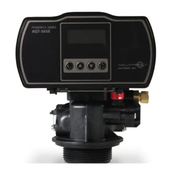
- Page 1 AQT 56SE ELECTRONIC SERIES CO NTR O L VA LV ES PROGRAMMING MANUAL...
-
Page 2: Table Of Contents
3/4" Turbine Assembly & Parts List Powerhead Assembly Powerhead Assembly Parts List Control Valve Assembly Control Valve Assembly Parts List Valve Wiring Diagram Troubleshooting Notes CON TR O L VALVE S AQUATROL | P.O. Box 2235 Chino Hills, CA 91709 • USA... -
Page 3: General Residential Installation
General Residential Installation CO N T RO L VA LV E S Water Pressure Minimum 25 PSI Electrical Supply Uninterrupted AC. Check voltage compatibility Existing Free of any deposits or build-ups inside pipes Softener Locate close to drain and connect according to plumbing codes Bypass Valves Always provide for bypass valve if unit is not equipped with one CAUTION... -
Page 4: Aqt-56Se Keypad
AQT-56SE Keypad CO N TR OL VALVE S Flow Meter Indicator Time of day 11:30 Status Volume Remaining 1 0 0 0 Regeneration mode - Timer - Meter Immediate - Meter Delay Settings Button Enter into setting menu Con rm the current setting, and enter into the next step When used simultaneously with up button, will enter into master programming Up Button Adjust current settings (increase) -
Page 5: Control Operation
CONTROL OPERATION Regeneration Modes CO N T RO L VA LV E S Time Clock Delayed Control A Time Clock Delayed Control regenerates the system on a timed interval. The control will initiate a regeneration cycle at the programmed regeneration time when the number of days since the last regeneration equals the regeneration day override value. -
Page 6: Master Programming - Setting The Time Of Day
Master Programming Setting the Time of Day CO N TR OL VALVE S First Step - Setting Time of Day Press Simultaneously 11:30 SET- 1TIME Default setting 12:00 (24 hours) Press Settings Button and Up Button simultaneously to enter into Programing Mode Flashing Set the hour... -
Page 7: Setting The Regeneration Mode
Master Programming Setting the Regeneration Mode CO N T RO L VA LV E S Second Step - Setting the Regeneration Mode 11:30 SET- 2TYPE Default setting is "Timer" Flashing Choose Between Time, Meter Immediate or Meter Delayed 11:30 Timer This mode will not show water TYPE-... -
Page 8: Setting The Unit Capacity
Master Programming Setting the Water Capacity CO N TR OL VALVE S Third Step - Setting the Unit Capacity (Not shown if Timer Mode was selected in 2nd Step) 11:30 SET-3 C-U Default setting is 1000 gal Flashing Set Unit Measurement - Gallons, Liters or Cubic Meters 11:30 Gallons 01000... - Page 9 Master Programming Setting the Water Capacity Cont. CO N T RO L VA LV E S 11:30 01000 Flashing 11:30 01000 Flashing Press Up or Down buttons 11:30 to set water capacity. 01000 Press the Settings Button to accept, cursor moves left and the number ashes.
-
Page 10: Setting The Regeneration Time & Hour Override
Master Programming Setting the Regeneration Time & Hour Override CO N TR OL VALVE S Fourth Step - Regeneration Time and Hours Override 11:30 SE T - 4 T-H Flashing Timer Mode Meter Imm & Meter Delay Modes Default: 2:00 a.m. – 072 hours Default: 2:00 a.m. -
Page 11: Setting The Backwash Time
Master Programming Setting the Back Wash Time CO N T RO L VA LV E S Fifth Step - Setting the Back Wash Time 11:30 SET-5 -BW- Flashing Set the Time Default setting is 015 11:30 -BW- Flashing Press Up or Down buttons to change Back Wash time 11:30 (Minutes) -
Page 12: Setting The Brine Time
Master Programming Setting the Brine Time CO N TR OL VALVE S Sixth Step - Setting the Brine Time 11:30 SET-6 -BD- Flashing Set the Time Default setting is 060 11:30 -BD- Flashing Press Up or Down buttons to change Brine time 11:30 (Minutes) Range: 0 - 999... -
Page 13: Setting Rapid Rinse Time
Master Programming Setting Rapid Rinse Time CO N T RO L VA LV E S Seventh Step - Setting the Rapid Rinse Time 11:30 SET-7 -RR- Flashing Set the Time Default setting is 010 11:30 -RR- Flashing Press Up or Down buttons to change the Rapid Rinse time (Minutes) 11:30... -
Page 14: Setting Brine Tank Fill Time
Master Programming Setting the Brine Tank Fill Time CO N TR OL VALVE S Eights Step - Setting the Water Filling Time 11:30 SET-8 -BF- Flashing Set the Time Default setting is 012 11:30 -BF- Flashing Press Up or Down buttons to change the Water Filling 11:30 Time (Minutes) -
Page 15: Product Features
Product Features Features & Displays CO N T RO L VA LV E S 1) Display in Service 11:30 Timed Regeneration Mode The display will show the current time, remaining time to the next set regeneration, and the days override. 02:18 01-D Reg. - Page 16 Product Features Features & Displays Cont. CO N TR OL VALVE S 3) Memory during power failure All program settings are stored in permanent memory. Current valve position, cycle step elapsed, time of day are stored during the power failure. Reset the current time is necessity when power up. If the valve stopped at a regeneration stage when power failure, the valve will return to prior position when power up.
- Page 17 Product Features Features & Displays Cont. CO N T RO L VA LV E S 5) Manual regeneration Immediate Regeneration When the valve is in service position, press and hold the button for 5 seconds, an immediate regeneration will be initiated. Examples: "BW"...
-
Page 18: Aqt-56Se Dimensional Drawings
AQT-56SE Dimensional Drawings CO N TR OL VALVE S Page 18... -
Page 19: 3/4" Turbine Assembly & Parts List
3/4" Turbine Assembly & Parts List CO N T RO L VA LV E S Item No. Quantity Part No. Description 56013 Flow Straightener 50022-8 Meter Cable Assembly 01013 O-ring 1220E Meter Body Assembly 50044 Adpater Clip 02105 Screw Page 19... -
Page 20: Powerhead Assembly
Powerhead Assembly CO N TR OL VALVE S Page 20... -
Page 21: Powerhead Assembly Parts List
Powerhead Assembly Parts List CO N T RO L VA LV E S Item No. Quantity Part No. Description A-15613 Front Cover A-S0001 Housing Assembly A-15616-1 Idler Pointer A-13312 Spring Idler A-13017 Idler Gear A-15617 Drive Gear A-14457 Spring A-13300 Ball A-15622-1 Main Gear and Shaft... -
Page 22: Control Valve Assembly
Control Valve Assembly CO N TR OL VALVE S Backwash Filter Injector Option Page 22... -
Page 23: Control Valve Assembly Parts List
Control Valve Assembly Parts List CO N T RO L VA LV E S Item No. Quantity Part No. Description A-02001 Screw A-02002 Screw A-13546 End Plug Retainer A-13363 Washer A-13296 Screw 66133 Piston Rod Assembly A-13446 End Plug Assembly 56115 Piston Retainer A-13247... -
Page 24: Valve Wiring Diagram
Valve Wiring Diagram CO N TR OL VALVE S Page 24... -
Page 25: Troubleshooting
Troubleshooting Problems, Cause & Corrections CO N T RO L VA LV E S Problem Cause Correction 1) The control fails to A) Disconnected meter cable A) Reconnect the meter cable Regenerate automatically B) Transformer damaged B) Replace the transformer C) Electronic controller or sensor damaged C) Replace or repair 2) Regeneration at wrong time... -
Page 26: Notes
Notes CO N TR OL VALVE S Page 26... - Page 27 Notes CO N T RO L VA LV E S Page 27...
- Page 28 CONTRO L VALV ES AQUATROL | P.O. Box 2235 Chino Hills, CA 91709 • USA...
Need help?
Do you have a question about the POWERFLO Series and is the answer not in the manual?
Questions and answers
manual start recycle
To manually start regeneration on the AQUATROL POWERFLO Series, press and hold the button for 5 seconds while the valve is in the service position. This will initiate an immediate regeneration.
This answer is automatically generated
WHERE CAN I FIND THE 'USER' MANUAL?
The user manual for the AQUATROL POWERFLO Series is available in the provided context. It includes sections such as installation instructions, timer settings, regeneration cycle programming, flow diagrams, assembly parts lists, troubleshooting, and wiring diagrams.
This answer is automatically generated