Table of Contents
Advertisement
Quick Links
- 1 Table of Contents
- 2 General Residential Installation Check List
- 3 Aqt-56St Softener Timer Control Valve Start-Up Procedures
- 4 Aqt-56Ft Filter Timer Control Valve Start-Up Procedures
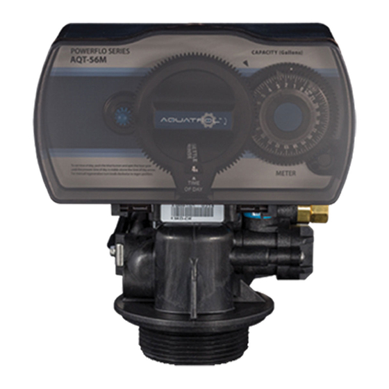
- 5 Aqt-56Sm Meter Control Valve Start-Up Procedures
- 6 Water Conditioner Flow Diagrams
- 7 Aqt-56St Softener Time Control Valve Drive Assembly
- Download this manual
Advertisement
Table of Contents

Related Manuals for AQUATROL AQT-56ST


Summary of Contents for AQUATROL AQT-56ST
- Page 1 AQT-56 POWERFLO SERIES CO NTR O L VA LV ES SERVICE MANUAL...
-
Page 2: Table Of Contents
TAbLE of CoNTENTS Products Checking List General Residential Installation Check List AQT-56ST Softener Timer Control Valve Start-up Procedures AQT-56FT Filter Timer Control Valve Start-up Procedures AQT-56SM Meter Control Valve Start-up Procedures Water Conditioner Flow Diagrams AQT-56ST Softener Time Control Valve Drive Assembly... -
Page 3: Products Checking List
MoDEL AQT-56 Product Check List CO N T RO L VA LV E S Products series check AQT-56ST (Softener timer) AQT-56SM (Softener timer) AQT-56FT (Filter timer) AQT-56FM (Filter meter) Other Model: _________________ Electric motor 110V/60Hz ... -
Page 4: General Residential Installation Check List
General Residential Installation Check List CO N TR OL VALVE S Water Pressure Minimum 25 PSI Electrical Supply Uninterrupted AC. Check voltage compatibility Existing Free of any deposits or build-ups inside pipes Softener Locate close to drain and connect according to plumbing codes Bypass Valves Always provide for bypass valve if unit is not equipped with one CAUTIoN... -
Page 5: Aqt-56St Softener Timer Control Valve Start-Up Procedures
MoDEL AQT-56ST Installation & Start-Up Procedure CO N T RO L VA LV E S bLUE TIME Model: AQT-56ST Manually index the softener control into the In Service position and let water flow into the resin tank. When the water flow stops, open a softened water tap until all air is released from the lines. -
Page 6: Aqt-56Ft Filter Timer Control Valve Start-Up Procedures
AQT-56fT Meter filter Valve Start-up Procedures CO N TR OL VALVE S bLUE TIME Model: AQT-56fT before Plugging in the Unit Open a treated water tap down stream of the filter. Manually index the filter to the In Service position and allow the mineral tank to fill by slowly opening the main water supply valve. Any bypass should be in the In Service position. -
Page 7: Aqt-56Sm Meter Control Valve Start-Up Procedures
AQT-56SM Meter Control Valve Start-Up Procedure CO N T RO L VA LV E S bLUE TIME Model: AQT-56SM Manually index the softener control to the In Service position and let water flow into the resin tank. When the water flow stops, open a softened water tap until all air is released from the lines. -
Page 8: Water Conditioner Flow Diagrams
Water Conditioner Flow Diagrams CO N TR OL VALVE S 1) Service Position Hard water enters unit at valve inlet and flows down Flow Control through the mineral in the mineral tank. Conditioned water Flow Control enters center tube through the bottom distributor, then Enjector Inlet flows up through the center tube, around the piston, and... - Page 9 Water Conditioner Flow Diagrams CO N T RO L VA LV E S 3) backwash Position Hard water enters unit at valve inlet, flows through piston, Flow Control down center tube, through bottom distributor, up the Drain Flow Control Enjector through the mineral, around the piston and out the drain Inlet line.
- Page 10 Water Conditioner Flow Diagrams CO N TR OL VALVE S 5) Slow Rinse Position (Softeners only) After all the brine has been drawn from the brine tank, Flow Control hard water continues to enter through the valve inlet, flows Drain Flow Control around the lower piston groove and through the nozzle Enjector...
- Page 11 Water Conditioner Flow Diagrams CO N T RO L VA LV E S 7) Settling Rinse Position Slow rinse of the resin bed. Water flows down through the Flow Control resin bed up the bottom distributor and out the drain. Drain Flow Control Enjector...
-
Page 12: Aqt-56St Softener Time Control Valve Drive Assembly
AQT-56ST Time Control Valve Drive Assembly CO N TR OL VALVE S AQT-56ST Time Control Valve Drive Assembly Page 12... -
Page 13: Time Control Valve Drive Assembly Parts List
Time Control Valve Drive Assembly Parts List CO N T RO L VA LV E S Item No. Quantity Part No. Description A-15613 Front Cover A-S0001 Housing Assembly A-13018 Idler Pointer A-13312 Spring Idler A-13017 Idler Gear A-13164 Drive Gear A-14457 Spring, Detent, Main Gear A-13300... -
Page 14: Aqt-56Sm Softener Meter Control Valve Drive Assembly
AQT-56SM Meter Control Valve Drive Assembly CO N TR OL VALVE S AQT-56SM Meter Control Valve Drive Assembly Page 14... -
Page 15: Meter Control Valve Drive Assembly Parts List
Meter Control Valve Drive Assembly Parts List CO N T RO L VA LV E S Item No. Quantity Part No. Description A-15613 Front Cover A-S0001 Housing Assembly A-13018 Idler Pointer A-13312 Spring Idler A-13017 Idler Gear A-13164 Drive Gear A-14457 Spring, Detent, Main Gear A-13300... -
Page 16: Control Valve Assembly
Control Valve Assembly CO N TR OL VALVE S backwash filter Injector option Page 16... -
Page 17: Control Valve Assembly Parts List
Control Valve Assembly Parts List CO N T RO L VA LV E S Item No. Quantity Part No. Description A-02001 Screw A-02002 Screw-Drive Retainer A-13546 End Plug Retainer A-13363 Washer A-13296 Screw A-13001 Piston Rod Assembly A-13446 End Plug Assembly A-12953 Piston Retainer A-10696... -
Page 18: Meter Assembly And Parts List
Meter Assembly And Parts List CO N TR OL VALVE S Item No. Quantity Part No. Description A-02082 Screw A-66120A Meter Cover Assembly, 10600gal A-66120B Meter Cover Assembly, 2100gal A-13847 O-ring, Meter Cover Assembly A-12204A Impeller A-13314 Screw, Adapter Clip A-13255 Adapter Clip A-13305... -
Page 19: Notes
CO N T RO L VA LV E S NoTES: Page 19... - Page 20 CONTRO L VALV ES AQUATRoL | P.O. Box 2235 Chino Hills, CA 91709 • USA...
Need help?
Do you have a question about the AQT-56ST and is the answer not in the manual?
Questions and answers