Table of Contents
Advertisement
Quick Links
Advertisement
Table of Contents

Subscribe to Our Youtube Channel
Related Manuals for PSS M Series


Summary of Contents for PSS M Series
- Page 2 All rights reserved. The information in this document is subject to change without notice. Publish statement Thank you for purchasing this series UPS. This series UPS is an intelligent, single phase in single phase out, high frequency online UPS designed by our R&D team who is with years of designing experiences on UPS.
-
Page 3: Table Of Contents
Contents 1.Safety ................................. - 2 - 1.1 Safety notes ............................- 2 - 1.2 Symbols used in this guide ......................- 2 - 2.Main Features ............................- 3 - 2.1 Summarization ............................ - 3 - 2.2 Functions and Features ........................ -
Page 4: 1.Safety
1.Safety Important safety instructions – Save these instructions There exists dangerous voltage and high temperature inside the UPS. During the installation, operation and maintenance, please abide the local safety instructions and relative laws, otherwise it will result in personnel injury or equipment damage. Safety instructions in this manual act as a supplementary for the local safety instructions. -
Page 5: 2.Main Features
2.Main Features 2.1 Summarization This series UPS is a kind of single phase in single phase out high frequency online UPS, it provides two capacities: The 6kVA and 10kVA. The products are modularized and adopt the N+X redundancy. It can flexibly increase the number of the UPS modules according to the load capacity which is convenient for flexible allocation and gradually investment. -
Page 6: 3.Installation
3.Installation 3.1 Unpack checking 1. Don’t lean the UPS when moving it out from the packaging 2. Check the appearance to see if the UPS is damaged or not during the transportation, do not switch on the UPS if any damage found. Please contact the dealer right away. 3. -
Page 7: Lcd Control Panel
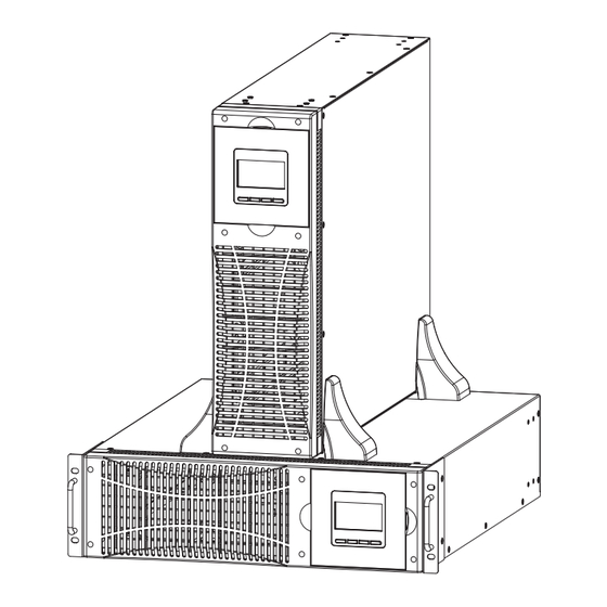
Side View (1) handles (2) fixing screw hole (3) LCD Display (4) Parallel Port 1 (5) USB port (6) Parallel Port 2 (7)COM(RS232) (8)Battery Slot (9)Output breaker (10) Intelligent slot (11) PDU (12) EPO (13) Input breaker (14) Input terminal (15) Output IEC (16) Output terminal 3.3 LCD control panel LCD control panel introduction... -
Page 8: Installation Notes
3.4 Installation notes ◆Please place the UPS in a clean, stable environment, avoid the vibration, dust, humidity, flammable gas and liquid, corrosive objects. To avoid from high room temperature, a system of room extractor fans is recommended to be installed. Optional air filters are available if the UPS operates in a dusty environment. -
Page 9: Power Cables
UPS Output ◆ Any external distribution board used for load distribution shall be fitted with protective devices that may avoid the risk of UPS overloaded. Over-current ◆ Protection device shall be installed at the distribution panel of the incoming main supply. -
Page 10: Power Cable Connect
3.7 Power cable connect Once the equipment has been finally positioned and secured, connect the power cables as described in the following procedure. Verify the UPS is totally isolated from its external power source and also all power isolators of the UPS are open. Check to see if they are electrically isolated, and post any necessary warning signs to prevent their inadvertent operation . -
Page 11: Ups Multi-Module Installation
Note: The BAT+ of the UPS connect poles is connected to the anode of the positive battery, the BAT- is connected to the cathode of the positive battery and the anode of the negative battery, the BAT- is connected to the cathode of the negative battery。... -
Page 12: Cabinet Installation
3.9.1 Cabinet installation Connect all the UPSes needed to be put into parallel system as below picture. Make sure each UPS input breaker is in “off” position and there is no any output from each UPS connected. Battery groups can be connected separately or in parallel, which means the system itself provides both separate battery and comman battery. -
Page 13: Requirement For The Parallel System
3.9.3 Requirement for the parallel system A group of paralleled modules behave as one large UPS system but with the advantage of presenting higher reliability. In order to assure that all modules are equally utilized and comply with relevant wiring rules, please follow the requirements below: 1) All UPS must be of the same rating and be connected to the same bypass source. -
Page 14: 4.Operation
4.Operation 4.1 Operation Modes The UPS is a double-conversion on-line UPS that may operate in the following alternative modes : ◆ Normal mode The rectifier/charger derives power from the AC Mains and supplies DC power to the inverter while floating and boosting charge the battery simultaneously. Then, the inverter converts the DC power to AC and supplies to the load. -
Page 15: Black(Cold) Start Procedure
The internal fan of the UPS starts spinning, the UPS is performing self-diagnostics until buzzer beeps twice to show the UPS is normal. Then, the UPS goes to bypass supply, Utility LED and Bypass LED turn Green, the inverter is starting up now. When the inverter is checked “normal”, the UPS goes to working mode and the load is supplied by the inverter now. -
Page 16: Disconnecting With Utility
4.2.4 Disconnecting with Utility CAUTION! This procedure should be followed to completely shut down the UPS and the LOAD. After all power switches, isolators and circuit breakers are opened, there will be no output. ◆After the inverter is off, turn the Utility and battery breakers to “OFF”, then the LCD display will extinguish completely and fan stops spinning in 60 seconds. - Page 17 Operational Status and mode When the UPS at single mode, it shows “NOA” or “ECO”or“CF”, but If the UPS at parallel mode, it shows “PAL” instead. 2) Press “DOWN” button, the UPS goes to next page as shown below. (2)Input voltage (3)Output voltage (4)Bat + voltage (Positive) (5)Bat –...
-
Page 18: Parameters Setting
4.4 Parameters setting The setting function is controlled by 4buttons (ENTER/ON, ESC/OFF, UP,DOWN): ENTER ---goes into the setting page and value adjustment; UP & DOWN ---for choosing different pages. After the UPS turn ON, press buttons UP & DOWN for 3 seconds and then goes into the setting interface page. -
Page 19: Output Frequency Setting
Press ESC/OFF button to exit the output voltage setting (save the output voltage setting) and goes to mode setting or frequency setting. NOTE: When powered by inverter, it is necessary to turn off the inverter before setting voltage and frequency level. 4.4.3 Output frequency setting Frequency setting (Note: Inside the broken-line is the flashing part.) -
Page 20: Battery Quantity Setting
Use button ENTER/ON to choose the different battery capacity. Battery capacity range is 1-200Ah. (Note: long-press of UP or DOWM can adjustment battery capacity quickly.) Press ESC/OFF button to exit the battery capacity setting (save the capacity setting) and goes to frequency setting or battery quantity setting. -
Page 21: Bypass Volt-Lo Setting
Press ESC/OFF button to exit the bypass voltage upper limit setting (save the bypass voltage upper limit setting) and goes to battery quantity setting or bypass voltage lower limit setting. 4.4.7 Bypass Volt-Lo setting Bypass voltage lower limit setting (Note: Inside the broken-line is the flashing part.) When under the bypass voltage upper limit setting press DOWN or when under parallel ID setting press UP, it goes to the bypass lower limit setting. -
Page 22: Battery Test Setting
4.4.9 Battery Test Setting Battery self-test setting This page is the introduction to the Battery self-test setting. The default Settings is “OFF” when the UPS has no need of the battery self-test function. When turn to “ON”, batteries can do the self-test automatically per 30 days. Three kinds of Battery Self-test Time can be chose as below. -
Page 23: Parallel Id Setting
4.4.10 Parallel ID setting Parallel ID setting (Note: Inside the broken-line is the flashing part.) When under the bypass voltage lower limit setting press DOWN or when under parallel quantity setting press UP, it goes to the parallel ID setting. The parallel ID flashes as in above picture. -
Page 24: Parallel Redundancy Quantity Setting
4.4.12 Parallel redundancy quantity setting Parallel redundancy quantity setting (Note: Inside the broken-line is the flashing part.) When under the parallel quantity setting press DOWN, it goes to the parallel redundancy quantity setting. The parallel redundancy quantity flashes as in above picture. ... -
Page 25: Appendix 1 Specifications
Appendix 1 Specifications Capacity 6kVA/5.4kW 10kVA/9kW Type 6kVA;10kVA Input mode Single phase + Ground Power factor ≥0.99 208/220/230/240Vac(can be set) rating voltage rating frequency 50Hz/60Hz(auto sensing) Voltage range 120~276Vac Frequency range 45~55Hz/54~66Hz 220Vac max:10%,15%,20% or 25%,default :25% 230Vac max:10%,15% or 20%,default +20% Bypass voltage range 240Vac max:+10% or 15%,default +15% min:20%, 30% or 45%, default 45%... - Page 26 <55dB(1m) Norse Display LCD+LED Safety Meeting IEC62040-1 GB4943 Max input voltage 320Vac,1Hr Conduction :IEC 62040-2 Radiation :IEC 62040-2 Harmonics :IEC 62040-2 IEC 62040-2 MTBF 250,000Hr 1+1 400,000Hr MTTR 30min Isolation resistance > 2MΩ(500Vdc) Isolation intension 2820Vdc, <3.5mA,1min Surge Meeting IEC60664-1 1.2/50uS+8/20uS 6kV/3kA. Protection IP20 Parallel circumfluence...
-
Page 27: Appendix 2 Communication Port Definition
Appendix 2 Communication port definition USB communication port Definition of Male port: Pin 1 VCC , Pin 2 D- pin 3 D+ , Pin 4 GND Application: use UPSilon2000 Power Management software Available functions of the USB ■ Monitor UPS power status ■... -
Page 28: Appendix 4 Ups Message Table
Appendix 4 UPS message table This section lists the event and alarm messages that the UPS might display. The messages are listed in alphabetical order. This section is listed with each alarm message to help you troubleshoot problems . 4.1 Operational Status and Mode(s) Note:“X”... - Page 29 Item UPS Alarm Warning Buzz DC Bus below voltage Beep continuously Fault LED lit DC bus unbalance Beep continuously Fault LED lit Soft start failed Beep continuously Fault LED lit Rectifier Over Temperature Twice per second Fault LED lit Inverter Over temperature Twice per second Fault LED lit Reserve...
Need help?
Do you have a question about the M Series and is the answer not in the manual?
Questions and answers