Table of Contents
Advertisement
Advertisement
Table of Contents

Related Manuals for Rendamax R18 Series


Summary of Contents for Rendamax R18 Series
- Page 1 TECHNICKÁ DOKUMENTACE...
- Page 2 We aim to achieve continuous improvement in our products. Therefore, specifications are subject to change without prior notice. Due to changes the product can deviate from the information specified in this document. Therefore Rendamax B.V. rejects any responsibility for the differences between the product delivered and the information mentioned in this document.
-
Page 3: Table Of Contents
Index R18 Technical data Dimensions Introduction Rendamax Supplier This manual Service General restrictions Description General information Main components Principle of regulation 2.3.1 EM Control 2.3.2 EW Control option Boiler protection Safety Delivery and transport Delivery Unit protective packaging Transport Installation Boiler room 5.1.1... - Page 4 Operation and fault indication Function Regulation Control panel Fault indications Start-up Shut-down Warnings Maintenance Safety General information Inspection Cleaning Servicing Component replacement Service Notes DOC2010/18en...
-
Page 5: R18 Technical Data
R18 Technical data Type Nominal heat output 1002 Nominal heat input (nett. CV) 1122 Gas consumption natural gas H 49,3 57,9 67,4 78,4 90,8 104,0 (10,9 kWh/m3) propane 19,0 22,1 25,7 29,9 34,7 39,7 Gas inlet pressure (min.) mbar (max.) mbar propane (max.) -
Page 6: Dimensions
Dimensions Flow Return STANDARD ALTERNATIVE The R18 unit is also available as a left -handed model. * Denotes minimum clearance for maintenance Fig. 1 Dimensions DOC2010/18en... -
Page 7: Supplier
1 Introduction 1.1 Rendamax Since its beginning in 1968, Rendamax has built up a strong reputation in industry for the development, production and marketing of gas-fired, high efficiency boilers in the 60 to 1200 kW range. Through their unique construction, these central heating units are renowned for their: high thermal effi... -
Page 8: General Restrictions
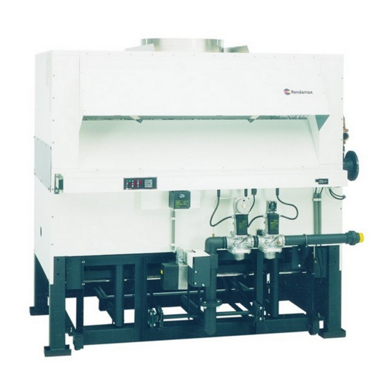
(legal or otherwise), specifications and standards applicable to such installations. All data, information and suggestions provided by Rendamax B.V. in relation to its products are based on careful investigation. Nevertheless, neither Rendamax B.V. nor any other organisation connected with Rendamax B.V. - Page 9 2.2 Main components Fig. 2 View of the R18 series Flue outlet socket Gas governor Draught diverter Main gas valve Cover for electrical connection tray Solenoid valve for pilot burner Connection tray Pressure test points Servomotor (air damper/gas input) Temperature control unit...
- Page 10 Fig. 3 Cross-section of the R18 series Flue outlet socket Modulating gas valve Deflector Servo motor Draught diverter Front adjusment strew forc air damper Air in-take Linkage assembly Heat exchanger Adjusment screw Connection tray Lock screw for air damper Combustion chamber...
- Page 11 Draught diverter The R18 is fitted with a draught diverter. It is possible to connect the flue outlet connection on the top cover to a standard flue pipe. The inside of the draught diverter is made of aluminium. The galvanized plate mantle is easily removed. Fig.
- Page 12 Heat exchanger The heat exchanger (type 2-pass) is mounted on the chassis. To ensure proper heat transfer of the combustion gases, the copper fin tubes are arranged side by side and expanded laterally into a mounting plate. The baffles on the copper fin tubes optimize the efficiency of the heat exchanger. The supply and return pipes, together with the water manifolds, form the heat exchanger.
-
Page 13: Principle Of Regulation
Combustion air damper A combustion air damper is situated underneath the burners. Fig. 8 Combustion air damper Gas train The principal components of the gas train are main governor and two main gas valves or combined main governor and main gas valve. The quantity of gas is adjusted in proportion of the quantity of air being supplied by the air damper opening. -
Page 14: Ew Control Option
Boiler temperature controller RWF40 A Process value (actual temperature) B Set point (temperature) C Burner enable (not applicable) D Mod. indicator (decrease fi re rate) E Mod. indicator (increase fi re rate) Two-stage firing (not applicable) G Limit comparator H Manual operation The keys K-L-M-N are used for displaying values and changing parameters in the temperature controllers confi guration. - Page 15 Outside temperature (°C) Fig. 9 Parallel displacement of the heating curve Heating curve slope Slope H of the heating curve can be used to adjust the set- point in response to the outside temperature, as shown in the diagram. The common origin of the heating curves is set at (20°C/20°C). The effective range of the weather- adjusted setpoint is restricted by the setpoint limits SPH and SPL.
- Page 16 Process data Parameter Display Value range Factory setting Setpoint 1 SPL-SPH Setpoint 2 (option) SPL-SPH Digital setpoint shift (option) SPL-SPH Outside temperature (option) C111 Inputs Predefinition of external setpoint SPL-SPH SP.E Parameter level Parameter Display Value range Factory setting Limit value of limit comparator -1999…+9999 digit Switching differential for limit comparator 0…999.9 digit...
-
Page 17: Boiler Protection
2.4 Boiler protection The R18 is protected by the following systems: Water flow switch The water flow switch is installed in the flow manifold and monitors continuously the water fl ow. As soon as the water flow stops, the burner is shut down and goes to lock-out. The water fl... - Page 18 Maintenance Work on the electrical installation should only be carried out by approved technicians and in accordance with the electro technic regulations. Work on the gas and hydraulic systems should only be carried out by approved technicians and in accordance with the safety regulations for gas installations. Keep unauthorized people away from the installation.
-
Page 19: Unit Protective Packaging
4 Delivery and transport 4.1 Delivery Before delivery, the R18 boiler is fully assembled and tested in the factory. The R18 is protecd by a wooden band and covered in a “heat-shrink” protective wrapper. Check for damage after removing the boiler’s protective covering. Check whether the boiler conforms to the order requirements. -
Page 20: Boiler Room Ventilation
The main gas service cock and gas filter should be supplied by a qualified heating engineer. Install the main gas service cock and the gas filter as close to the boiler as possible. The R18 series of boilers are suitable for connection to a 25 mbar gas network. DOC2010/18en... -
Page 21: Electrical Supply
The minimum supply pressure must never fall below 18 mbar. With a lower gas pressure it is possible that the boiler will not run at 100% capacity. At the same time the boiler can be more prone failures. Adjust the burner pressure with a supply pressure of 20 mbar. - Page 22 pressure relief valve flow and return headers fill and drain cocks Fig. 14 Support fl ow and return pipes 5.2.4 Boiler room ventilation The product has to be installed by a recognized installer fully according to the current national and local demands, norms and standards.
-
Page 23: Flues
The openings shall be sited so that they cannot be easily blocked or flooded. The grilles shall have a total minimum free area as follows, taking account of all fuel burning appliances. Fig. 16 Extraction cap Fig. 17 Air inlet openings Low level inlet 540 sq. -
Page 24: Water Quality
You can use the following information to assist in flueing: Type Q flue m Chimney diameter mm 1770 2062 2421 2811 3270 3751 Table 2 Flue gas volumes Heat input: 100% Flow temperature: 90°C Return temperature: 70°C Flue gas temperature: 130°C 5,5% Flue condensation... -
Page 25: Hydraulic System
During the construction of larger installations, one of the appliances may be operational. New circuits may be regularly switched in, which must occur together with the addition of fresh water. In addition, it can happen that, because of leakage, some circuits must be disconnected, repaired and re-filled. - Page 26 p exp. Fig. 18 Example of a hydraulic system Minimum and maximum water volume per hour A too low flow rate through the copper fin tubes can lead to cavitation. Also a too high flow rate can cause erosion. To protect the heat exchanger from these two extremes, the flow rate (Q) should be set using the table below.
-
Page 27: Examples Hydraulic System
Positioning the pump and expansion vessel We advise that the pump should be mounted in the return pipe in the following order: expansion vessel, pump, boiler. If you mount the pump in the flow pipe, the lifespan of the pump will be reduced. Always connect the expansion vessel to the suction side of the boiler pump. - Page 28 Example of a low velocity header with isolating valves and an expansion tank. Fig. 20 Installation with a low velocity header, isolating valves and expansion tanks Mounting the low velocity header vertically has additional advantages: the upper section functions as an air separator and the lower section serves as a drain. When air heaters (for ventilation or air treatment) are included in the system it is generally desirable to have a small ∆T over the air heaters.
- Page 29 Fig. 21 Boiler with vertically mounted low velocity header arranged with right hand connections Fig. 22 Low velocity header with multiple heating circuits in a mixing control arrangement without a main pump Open vent and cold feed An open vent pipe must be fitted in open systems not more than one meter along the flow pipe and must rise continuously by the shortest route to the venting point without valving and with frost protection where necessary.
- Page 30 Installations with multiple appliances For installations in which each appliance is fitted with a pump, the pump is switched off after the boiler has been shut down. Fig. 23 Installation with multipple appliances Hydraulic short-circuit In order to avoid a short circuit over a non-operating appliance, we advise the use of non-return valves. These may be either mechanically or electrically operated valves.
-
Page 31: Pre-Lighting Checks And Dry Run
6 Commissioning 6.1 General COMMISSIONING OF THE BOILER MUST BE CARRIED OUT BY PROPERLY QUALIFIED AND AUTHORISED PERSONNEL. OTHERWISE, THE GUARANTY WILL BECOME VOID. Never deviate from the instructions in this manual. Flushing the system To prevent damage from rust, sealing compounds, sand, metal particles etc., the system must be flushed thoroughly, before the system is switched on. - Page 32 Check that the direction of rotation of the pump(s) is correct. Components within the connection tray (Remove cover from electrical connection tray) fixing screw cover fixing screw temperature control unit control panel hours run indicator high limit thermostat Fig. 25 Connection tray II) Check the setting of the modulating combustion air damp er situated underneath the burners, there should be a gap of 8 mm with the damper in the fully closed position against the stops.
-
Page 33: Check 3
6.2.3 Check 3 With the electricity supply switched off check the gas train downstream of the gas inlet service cock as follows: Refer to Gas trains, fig. 34 for particular boiler model. 1. Ensure that gas service cock is closed. 2. -
Page 34: Live Run Check
Liquid Propane Gas Gas service pressure 50 mbar / Nozzle diameter 1 mm minimum load (20 %) Type Burner pressure Pilot pressure Air damper opening closed Cascade out start/min. (mbar) (mbar) (mm) (mbar) full load (100 %) Type Burner pressure Pilot pressure Air damper opening Cascade in... -
Page 35: Instructions To User
Switch the on/off switch to on and the boiler will ignite in the sequence described in a) above with the main burners igniting from the pilot burner at minimum rate. Check ignition of the main burners is smooth. Observe that the modulating air damper opens and the gas rate increases to maximum. Check the main burner pressure on maximum is as indicated in table 7 and adjust if necessary. -
Page 36: Regulation
Boiler failure In case of boiler failure the system will fall into lock-out. Reset the boiler with the reset button on the control panel. Repeat this several times if necessary. If the boiler still does not start, refer to chapter ‘Operation and fault finding’... -
Page 37: Fault Indications
Fig. 29 Electronic RWF40 A Process value (actual temperature) B Set point (temperature) C Burner enable (not applicable) D Mod. indicator (decrease fire rate) E Mod. indicator (increase fire rate) Two-stage firing (not applicable) G Limit comparator H Manual operation The keys K-L-M-N are used for displaying values and changing parameters in the temperature controllers configuration. -
Page 38: Start-Up
7.5 Start-up Ensure that gas and electric supplies are connected. Start sequence: A Turn manual gas cock open B Turn the pumps on C Ensure that all hot water outlets are closed D Turn the supply voltage to the boiler on and turn the boiler on using the power switch 1 E In case of failure, observe type of failure, take necessary steps to rectify, refer to section 4 for details Set temperature regulator as required. - Page 39 Fault Possible cause Solution Boiler does not attempt to light No electrical supply to boiler Check whether switched indicator (1) is alight Check all external controls for continuity No heat demand Check control thermostat is set high enough High limit thermostat has operated If lamp 2 is illuminated, press reset button and allow unit to fire.
- Page 40 Fault Possible cause Solution Air modulating damper HT lead disconnected or faulty Correct cycles, no ignition spark and boiler then goes to lockout, Ignition electrode incorrectly set or Check setting or replace indicator (2) alights faulty Faulty ignition generator Change Faulty control box Change box Ignition sparks, pilot burner does...
-
Page 41: Maintenance
8 Maintenance 8.1 Safety Always wear the proper protective clothing and shoes when servicing the boiler. Wearing jewelry and loose clothing can contribute to unsafe situations. 8.2 General information In order to keep the R18 in a safe working condition, the boiler should be inspected and serviced at least once every year and cleaned if necessary. -
Page 42: Cleaning
Fig. 31 Inspection and cleaning of the draught diverter and heat exchanger After removing the burner, the combustion chamber and the underside of the heat exchanger can easily be inspected. Heat exchanger (internal inspection) Internal inspection must be carried out by qualified and authorised personnel. Sight glass A sight glass can be found on the left hand side (on alternative handings the sight glass will be located on the right side) of the burner assembly for inspection of:... -
Page 43: Servicing
This may be caused by: insufficient ventilation condensate on the heat exchanger. If this is the case, clean the complete heat exchanger, including the baffles. Furthermore, the cause of the problem should be ascertained and rectifi ed. Heat exchanger (internal cleaning) Descale the heat exchanger with the correct chemicals. - Page 44 Remove the stainless steel sidebaffles down holders by releasing two screws in either side and remove the fl ueway baffles from the top of the heat exchanger. Inspect the heat exchanger for deposits and clean if necessary, check condition of the copper fin tubes and replace flueway baffl es when damaged.
-
Page 45: Component Replacement
Fig. 33 Electrodes Check that the modulating combustion air/gas control linkages are in good working order and that there is no play in the gas control spindle. Replace the burner trolley and bolt into position. Re-connect the electrical connectors to the connection tray. Recommission the boiler as described in Section 6 commissioning. - Page 46 Injectors Remove the burner trolley and burner bars as described before. With the burner bars removed the injectors can be unscrewed from the gas manifold. Ensure that injectors are unblocked and are the correct size - 1.85 mm diameter (natural gas). Use an approved pipe sealant on the injector thread to ensure a gas sound seal.
- Page 47 Replacing fin tubes Header and manifold removal. Release water pressure and drain the unit. Disconnect the system water-pipes at the manifold flanges. Remove all pressure and temperature sensors from the flow/return manifolds immersion tubes then electrically disconnect the flow-switch. Remove the manifold and header retaining bars (10) and carefully remove the water manifolds, spacer plate and “O”-rings.
-
Page 48: Service
After expanding Before expanding Fig. 35 Expanding the fi n-pipe ends Fig. 36 Tightening the manifold nuts 8.7 Service For service and maintenance the service department of your supplier is always available. DOC2010/18en... -
Page 49: Notes
Notes DOC2010/18en... - Page 50 Notes DOC2010/18en...
- Page 51 Notes DOC2010/18en...
- Page 52 Rendamax bv Service: Hamstraat 76 6465 AG Kerkrade Parkstad nr. 5007 P.O. Box 1035 6460 BA Kerkrade The Netherlands Tel. (+31) 45 5669 900 Fax (+31) 45 5669 910...
Need help?
Do you have a question about the R18 Series and is the answer not in the manual?
Questions and answers