Table of Contents
Advertisement
Quick Links
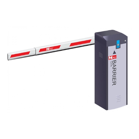
BR600T Series
MAG Intelligent Vehicle Barrier Gate
1) Warranty Coverage
MAG warrants each new product manufactured and sold by it or one of its authorized
distributors only againts defects in workmanship and/or materials under normal service,
proper installation and use. THIS WARRANTY IS LIMITED TO REPAIR OR REPLACEMENT OF
VERIFIED DEFECTIVE PRODUCTS AND EXCLUDES ANY AND ALL RISK AND LIABILITY
WHATSOEVER RESULTING FROM ANY USE OF SAID PRODUCTS, INCLUDING INCIDENTAL AND
CONSEQUENTIAL DAMAGES. THERE ARE NO WARRANTIES WHICH EXTEND BEYOND THE
DESCRIPTION ON THE FACE THEREOF. The provisions of this warranty and limitation of liability
shall not modified in any respect except by written document signed by MAG.
2) Warning
!
a) In case of emergency, isolate power from the power supply.
b) Operate your barrier from suitable AC220 volts.
c) Improper installation can create danger (such as electric shock or fire). Please engage
specialist for the proper installation work.
d) Do not install Barrier Gate in a potentially explosive atmosphere.
e) If abnormal condition (burnt smell , etc...) occurs, switch off the power supply immediately.
3) Production Type
Feature
Open/close
Model No.
BR618T
1.8 sec
BR630T
BR660T
BR630T_90
BR660T_FE
4) Technical Specification
Description
Mechanical temperature
Electrical temperature
Power supply input
Power consumption
Relative humidity
Arm speed
Internal lubrication
Max starting torque
AC rotation speed
5) Product Elements
5.1) Barrier Parts
Top Cover
Arm
Body Housing
5.2) Motor Parts
Arm Tray
Balance Crank
Screw Threadpole
Initiative Crank
Spring Base
Balance Spring
User Manual v.1 2015
Max straight
Arm swing
speed
arm
out
4 meter
Yes
3 sec
4 meter
Yes
6 sec
6 meter
No
3 sec
4 meter
No
6 sec
4.5 meter
No
Parameter
-40° to 75 C
-10° to 75 C
220V ± 10% AC, 50/60Hz
80 watt
< 90 %
1
8 .
,
3
,
6
s
e
c
o
n
d
Grease
1.8 second : 1.4±0.2 N .M
3 / 6 second : 0.8 7±0.1 N .M
1.8 second : 44 0±40 R P M
3 / 6 second : 900±5 0 R P M
Top cover can remove
from the body house
Key opening to
unlock clutch
Key (to lock &
unlock the clutch)
Housing door
can remove
from body
housing
Housing Door
U-channel bracket and plug bolt
for installing barrier gate
Diagram 5.1
Brace pole
Rubber cushion
Ir sensor limit
Drive Crank
Motor
Motor Sensor
Spring Pin
Diagram 5.2
6) Base Installation
6.1) Mount the barrier base on the ground with screws. Refer to diagram below :
33 cm
Arm at this side
19.5cm
13cm
Door at this side
Diagram 6.1
6.2) Do marking on the ground base on plug bolt distance (refer to diagram 6.2)
6.3) Screw U-Channel Bracket on the ground (refer to diagram 6.3)
U-Channel Bracket
D o o r
a t t h i
s s i d e
b e f o
r e c o
m p le
t e ly s
e c u r
in g t
h e n
u t s .
7) Arm Installation
a) Mount the arm at the arm tray by screw. Refer to diagram 7.1
Arm Tray
Plastic Clip
Mount the arm
at the arm tray
b) Assemble telescopic arm. Refer to diagram 7.2
Step 1:
Find 2 nos screw
from arm cover
Diagram 7.2
8) Manual release arm by releasing clutch.
Arm can be move manually after unlocking the clutch.
This is useful during power failure where user can
manually lift the arm allowing traffic to pass through.
8.1) During power failure :
Step 1 : Turn key anti-clockwise to unlock the clutch
Step 2 : Lift arm vertical 90 degree
Step 3 : Turn key clockwise to lock the clutch
8.2) After power resume :
While arm still lift up
Step 1 : Press push button "UP" button one time
Step 2 : Press push button "DOWN" button.
Barrier arm will resume back to normal operation.
9) Counter - Weight spring adjustment
9.1) Selection of the spring
Green Spring
Features
(4.0mm )
Model
BR618T
2
BR630T
1
BR660T
BR630T_90
1
BR660T_FE
9.2) Calibrating counter-weight spring tension
Tension of counter weight spring needs to be calibrated according to arm length and weight
to achieve minimum burden on the motor. This will ensure maximum life time on the motor.
Step 1 :
Turn the key clockwise to unlock the clutch. Refer diagram 9.2a
Plug Bolt Nuts
U-Channel Bracket
A r m a t
Barrier Base
Plug Bolt
D o o r
a t t h i
s s i d e
Barrier
Body Housing
A r m a t
t h i s s i d
e
Plug Bolt
Barrier Base
Diagram 6.3
Barrier Arm
Diagram 7.1
Step 2:
Secondary arm must be fully
pulled out. Mount 2 screws
tightly at the middle section to
secure
the
primary and secondary arm.
Arm will shake if screw is not
mounted tightly. Secondary
arm can be cut shorter to
adjust to lane.
Lock
UnLock
Red Spring
Blue Spring
(4.5mm )
(5.5mm )
1
1
1
1
1
1
UnLock
diagram 9.2a
t h i s s i d
e
Diagram 6.2
join
between
Advertisement
Table of Contents

Related Manuals for MAG BR600T Series


Summary of Contents for MAG BR600T Series
- Page 1 33 cm 1) Warranty Coverage U-Channel Bracket Arm at this side MAG warrants each new product manufactured and sold by it or one of its authorized A r m a t t h i s s i d 19.5cm distributors only againts defects in workmanship and/or materials under normal service, proper installation and use.
- Page 2 DETECTOR OUTPUT OUTPUT MOTORCADE SIGNAL POWER LINE R&G LIGHT 12ACV SERIAL COMMUNICATION Loop detectcor Stop Down Manual Push Button Infrared sensor AC 230v Loop Coil AC 230v 60Hz MAG BR CTRL Control Panel Compatible with BR618T, 630T, 660T Connection layout...
Need help?
Do you have a question about the BR600T Series and is the answer not in the manual?
Questions and answers