Table of Contents
Advertisement
Quick Links
Advertisement
Table of Contents

Subscribe to Our Youtube Channel
Related Manuals for Datavideo WM-10

Summary of Contents for Datavideo WM-10
- Page 1 WM-10...
-
Page 2: Table Of Contents
Assembly Steps of the WM-10 ............. 7 How to install the WM-10 to the Wall ..........7 Introduction of the Bubble Level Meters of the WM-10 ..... 11 Important Notices for installing PTR-10/PTR-10T Robotic Pan Tilt Head and PTC-150 Series Cameras to WM-10 ..........12 For installing PTR-10/PTR-10T ............ - Page 3 Disclaimer of Product & Services The information offered in this instruction manual is intended as a guide only. At all times, Datavideo Technologies will try to give correct, complete and suitable information. However, Datavideo Technologies cannot exclude that some information in this manual, from time to time, may not be correct or may be incomplete.
-
Page 4: Fcc Compliance Statement
AC adapter. If you are not sure of the type of power available, consult your Datavideo dealer or your local power company. 8. Do not allow anything to rest on the power cord. Do not locate this unit where the power cord will be walked on, rolled over, or otherwise stressed. -
Page 5: Warranty
Warranty Standard Warranty Datavideo equipment are guaranteed against any manufacturing defects for one year from the date of purchase. The original purchase invoice or other documentary evidence should be supplied at the time of any request for repair under warranty. -
Page 6: Three Year Warranty
DVD drives, Hard Drive, Solid State Drive, SD Card, USB Thumb Drive, Lighting, Camera module, PCIe Card are covered for 1 year. The three-year warranty must be registered on Datavideo's official website or with your local Datavideo office or one of its authorized distributors within 30 days of purchase. -
Page 7: Disposal
Disposal For EU Customers only - WEEE Marking This symbol on the product or on its packaging indicates that this product must not be disposed of with your other household waste. Instead, it is your responsibility to dispose of your waste equipment by handing it over to a designated collection point for the recycling of waste electrical and electronic equipment. -
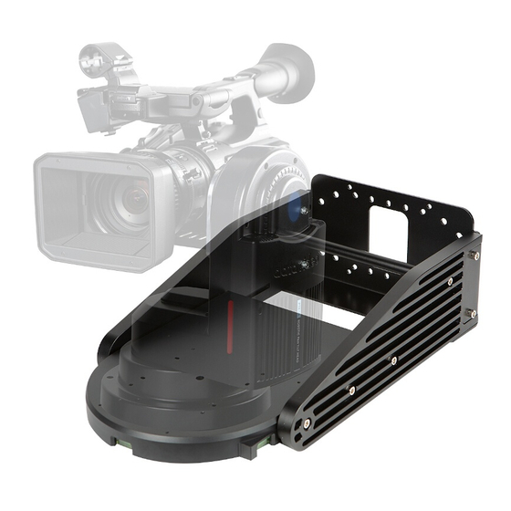
Page 8: Professional Wall Mount Kit For Datavideo Robotic Pan Tilt Head
No.1 to No. 4 order. Step 3. After the back plate (A) of the WM-10 is fixed to the wall, please screw the No.5 and No.6 screws with nuts to the left-side plate(C) for connecting the left side plate(C) to the back plate(A) of the WM-10 according to following diagram Figure 1. - Page 9 10 according to following diagram Figure 1. Step 5. Please place the round rod into the space of the WM-10. Step 6. Please align the left side of the round rod to the screw hole of the left side plate according to the following diagram Figure 1.
- Page 10 Step 13. Please align the PTR-10 or PTR-10T to the bottom plate(D) of the WM- Step 14. Please screw four screws from the bottom of the WM-10 bottom plate(D) according to the following diagram Figure 2 for fixing the PTR-10/PTR-...
- Page 11 Figure 1. WM-10 Assembly...
-
Page 12: Introduction Of The Bubble Level Meters Of The Wm-10
The WM-10 Professional Wall Mount for Robotic Pan Tilt Head provides users two Bubble Level Meters for measuring whether the WM-10 is installed horizontally or not. The two Bubble Level Meters are located at the bottom of the WM-10. ... -
Page 13: Important Notices For Installing Ptr-10/Ptr-10T Robotic Pan Tilt Head And Ptc-150 Series Cameras To Wm-10
Head and PTC-150 Series Cameras to WM-10 For installing PTR-10/PTR-10T For installing PTR-10/PTR-10T Robotic Pan Tilt Head to WM-10, it is recommended that all of the six screw holes on both side plates (including screw holes 13,14,15 & 16,17,18) must be screwed by using screws. - Page 14 For installing the PTR-10/PTR-10T to the WM-10, please screw four screws (No. 9, No. 10, No. 11 & No. 12) from the bottom of the bottom plate according to following diagram. Figure 2 Installing PTR-10/PTR-10T to WM-10(must be screwed from bottom)
-
Page 15: For Installing Ptc-150
For installing PTC-150 For installing PTC-150 series camera to the WM-10, it is recommended that users can screw the first or the third (13 or 15/16 or 18) screw hole on both side plates. And then the PTC series camera can be moved forward and backward by using internal rails which are located at both side plates. - Page 16 Step 4. Please install the PTC-150 camera to the Ceiling Lower Covering Plate according to following diagram. Step 5. Please install the PTC-150 camera module to the WM-10 according to following diagram.
-
Page 17: Weight
FEC. Weight Weight of the WM-10 3.95 Kg = 8.70 lb Maximum Load Weight Limit 10Kg * Please note that the WM-10 wall mount kit can be applied to the PTR-10/PTR-10T and PTC-150 series. -
Page 18: Dimensions
Dimensions Unit: mm... -
Page 19: Wm-10 Accessory List
WM-10 Accessory List WM-10 Accessory List Item Back Plate Side Plate (L) Side Plate (R) Bottom Plate Round rod Expansion screw Hexagon socket screw (M5 x 20mm) Screw Nut (M5) Screw with spring washer (M3 x 10mm, for mounting PTR-10/10T) -
Page 20: Service And Support
Datavideo Technologies Co., Ltd. All rights reserved 2020 G082062864E1 Jan-09.2020 Ver:E1...
Need help?
Do you have a question about the WM-10 and is the answer not in the manual?
Questions and answers