
Subscribe to Our Youtube Channel
Related Manuals for Gardner Denver TR20


Summary of Contents for Gardner Denver TR20
- Page 1 Installation, Operating & Maintenance Manual (Original Instructions) TR20 SCREW COMPRESSOR Models TR20 Rear ACW TR20 Rear CW 4990497003 November 2016...
-
Page 2: Table Of Contents
Schedule ................22 Change Gear Case Oil ........... 22 Valves .................. 23 Silencers/Pipework ............23 Air Inlet Filter - cyclonic ..........24 Alternative Oils ..............24 Service Maintenance sheet......... 25 4990497003 Date: 11/2016 TR20 Installation, Operating & Maintenance Manual Page 2... -
Page 3: Health & Safety
Relief Valve Check This procedure should be carried out every month to clear the valve seat and check the valve is functional. (Ear protection is recommended) 4990497003 Date: 11/2016 TR20 Installation, Operating & Maintenance Manual Page 3... -
Page 4: General
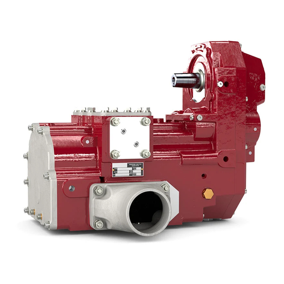
General Product general description The TR20 is a robust, high flow, oil free, contactless, low maintenance screw compressor designed for the contaminant free discharge of a wide range of product types including the following: 1. Granular, pellet and random particle products at 1-1.5 bar g (e.g. -
Page 5: Available Packages
Reactive, Separate Ancillaries NOTE A number of optional/locally supplied items are pictured, please refer to pages 14 & 15 for details of package contents. Figure1. Standard Packages (1 & 2 ) 4990497003 Date: 11/2016 TR20 Installation, Operating & Maintenance Manual Page 5... -
Page 6: Dimensions, Performance Data, And Operating Environment
General Dimensions, Performance data & Operating Environment Dimensions The dimensions of the basic TR20 are shown in figure 2 below. Performance The performance details and power requirements of the compressor are shown on CAUTION the product data sheet. For additional information, the constant running torque does not exceed:... -
Page 7: Installation
The basic compressor is supplied with an eyebolt attached for lifting. the machine. When the machine has been installed, the eyebolt should be removed. Any equipment used for lifting should be rated accordingly. Figure 3. Lifting 4990497003 Date: 11/2016 TR20 Installation, Operating & Maintenance Manual Page 7... -
Page 8: Mounting
Installation Mounting NOTE The TR20 should be installed vertically utilising all three mounting feet on one side of the machine. The drive direction is specific to machine and is shown on the machine The compressor has three itself (arrow indicating rotation next to input shaft). Additionally, the machine has mounting feet on each side discharge flanges on both sides and above. -
Page 9: Lubrication
Figure 5. Mounting Details - separate ancillary packages NOTE Lubrication The TR20 is supplied complete with oil. Taper washers should be used if mounting channels When the compressor has been mounted, the oil level should be re-checked as... -
Page 10: Pto And Prop Shaft Drive Alignment
Key, Parallel Rectangular Round End 10 x 8 x 50 Long Socket Head Cap Screw M12 x 40 Long NOTE Cap Screw (Item 5) should be tightened to a torque of 88Nm. Figure 7b. DIN Friction Coupling 4990497003 Date: 11/2016 TR20 Installation, Operating & Maintenance Manual Page 10... - Page 11 12° (see figure 8). NOTE Figure 7c. SAE Friction Coupling Also check the prop shaft manufacturers’ information for the permitted installed angle. Figure 8. Drive Alignment 4990497003 Date: 11/2016 TR20 Installation, Operating & Maintenance Manual Page 11...
-
Page 12: Pipework
NOTE • A flexible element is recommended in the discharge pipework (and inlet pipework when necessary) to prevent distortion of the TR20 from the fabricated Tighten item 1 fig. 9 to a pipework through chassis movement and heat expansion. -
Page 13: Ancillaries
(as shown in fig 10 ). It is pre-set, wired and leaded (tamper proof ) and fitted to protect the TR20 (rather than the system which should be protected by the vehicle tank relief valve) against Fig 10. -
Page 14: Package 1 Layout/Parts
Friction Coupling (K1310/DIN100) Gasket - Outlet Port Storz Coupling - 3” BSP Outlet Blanking Flange Inlet Blanking Flange Secondary Outlet Gasket Secondary Outlet Flange Figure 10a Absorptive, separate ancillaries. 4990497003 Date: 11/2016 TR20 Installation, Operating & Maintenance Manual Page 14... -
Page 15: Package 2 Layout/Parts
Gasket - Outlet Port Shear Coupling (K1310/DIN100) Outlet Blanking Flange Storz Coupling - 3” BSP Inlet blanking flange Secondary Outlet Gasket Secondary Outlet Flange Figure 10b Reactive, separate ancillaries. 4990497003 Date: 11/2016 TR20 Installation, Operating & Maintenance Manual Page 15... -
Page 16: Pre-Commissioning Check List
These should be removed and replaced with a temperature probe and a pressure probe for commissioning only. (see Fig. 11) If Gardner Denver supplied flanges are not used, the installer must provide 2 x 1/4” BSP tappings adjacent to the inlet and outlet ports for the commissioning test probes. -
Page 17: Commissioning Procedure
Commissioning Commissioning Procedure All procedures and temperature readings should be taken via the 4 probes fitted in the TR20 inlet and outlet flanges. Tick when completed 1 Check that the discharge gate valve on the pipework is open. 2 Start the engine, depress the clutch and allow the vehicle gearbox parts to stop rotating (5 seconds should be sufficient). - Page 18 Commissioning Description Pressure Manometer Temperature Gauge Pressure Tapping (Inlet depression) Temperature Tapping (Inlet) Commissioning Filter Pressure Gauge Pressure Tapping (Discharge) Temperature Tapping (Discharge) Figure 12. Commissioning Tests 4990497003 Date: 11/2016 TR20 Installation, Operating & Maintenance Manual Page 18...
-
Page 19: Driver Operating Instructions
2.2 bar gauge. Where the operator will be subjected to prolonged exposure To prevent high shaft torque and material blow-back, the TR20 should never be to noise, it is recommended that started directly against a pressurised tank. Mid-delivery re-starting should only be ear protection is provided. -
Page 20: Driver Training
• Unloading valve Routine Maintenance Instruct the driver regarding: • Gearbox oil - topping-up and replacement • Air filter - cleaning/replacing • Pipe connections - checking • Relief valve function 4990497003 Date: 11/2016 TR20 Installation, Operating & Maintenance Manual Page 20... -
Page 21: Commissioning Test Sheet
Commissioning 4990497003 Date: 11/2016 TR20 Installation, Operating & Maintenance Manual Page 21... -
Page 22: Maintenance
4. Clean and then refit drain plugs and re-fill the gearcase with approximately 2.5 litres of oil. 5. Ensuring that the TR20 is level, check oil level by removing a fill plug. There should be a slight leakage of oil with the plug removed. -
Page 23: Valves
The silencers and pipework should be inspected for signs of damage or corrosion. When paintwork is damaged, clean off any corrosion and treat with rust inhibitor before repainting. Use paints that can withstand temperatures of 180°C. 4990497003 Date: 11/2016 TR20 Installation, Operating & Maintenance Manual Page 23... -
Page 24: Air Inlet Filter - Cyclonic
Figure 14a. Replacing Air Filter Alternative Oils NOTE The TR20 is supplied filled with GD AEON S150 synthetic oil. Other ISO 150 Poly alpha ISO 150 EP grade oils from Olefin (PAO) grade oil with EP (extreme pressure) additives can theoretically be used, different manufacturers can be but may affect the long term reliability of the machine. -
Page 25: Service Maintenance Sheet
For the annual/ 500 operational hours service, initial the box as each check is completed. MONTH DATE DATE DATE DATE DATE Oil & filter change Air Filter Check Valve Relief Valve Silencers Pipework 4990497003 Date: 11/2016 TR20 Installation, Operating & Maintenance Manual Page 25... - Page 26 Gardner Denver Ltd PO Box 178, Springmill Street, Bradford, West Yorkshire, UK BD5 7HW Tel: +44 (0)1274 718100 Fax: +44 (0)1274 655272 Email: gdtransportsales@gardnerdenver.com Web: www.gd-transport.com © 2016 Gardner Denver Ltd. 4990497003 Date: 11/2016 TR20 Installation, Operating & Maintenance Manual Page 26...
Need help?
Do you have a question about the TR20 and is the answer not in the manual?
Questions and answers