Table of Contents
Advertisement
Quick Links
Advertisement
Table of Contents
Troubleshooting

Related Manuals for ZONARE Z.ONE PRO


Summary of Contents for ZONARE Z.ONE PRO
- Page 1 ZONARE z.one Ultrasound System Service Manual...
- Page 2 ©2019 Shenzhen Mindray Bio-Medical Electronics Co., Ltd. All rights Reserved. ZONARE, the ZONARE logo, ZS3 and z.onepro are all trademarks of shenzhen mindray Bio-Medical Electronics Co., Ltd. All other trademarks are the property of their respective holders. The z.one Ultrasound System is covered by one or more of the following patents: 6,251,073; 6,569,102; 6,618,206; 6,663,567;...
-
Page 3: Table Of Contents
TABLE OF CONTENTS INTRODUCTION ............................8 TECHNICAL SUPPORT ............................8 EMAIL: TECHSUPPORT@ZONARE.COM ......................8 SALES SUPPORT: 1-877-966-2731, SALESSUPPORT@ZONARE.COM ............ 8 PURPOSE ..............................9 Product Overview ............................. 9 Definitions/Acronyms ............................9 Documentation Conventions ......................... 11 SAFETY ............................... 13 WARNINGS & Cautions ..........................13 SYSTEM SPECIFICATIONS ........................ - Page 4 ZONARE MODULE COVER INSTRUCTIONS ..................... 45 System Verification .......................... 46 z.one BASIC SYSTEM CONFIGURATION ....................... 49 Entering “Institution” Name ........................... 49 Configuring “Barcode” Scanner ........................50 Configuring “Audio/Video” ..........................51 Entering “Time/Region” Information ......................52 Entering “Trackball” Configuration ....................... 53 Configuring “Imaging”...
- Page 5 Technical Support Contact Information ..................... 146 TECHNICAL SUPPORT ............................ 146 EMAIL: TECHSUPPORT@ZONARE.COM ....................146 SALES SUPPORT: 1-877-966-2731, SALESSUPPORT@ZONARE.COM ..........146 Troubleshooting ............................147 System Status LED & Error Code Definitions ..................152 Battery Performance – Charge Times - Reconditioning ................. 161 17 REPLACEMENT PROCEDURES ......................
- Page 6 DVD Drive – Removal/Replacement ......................198 Transducer TCON Board – Removal/Replacement ................200 System ................................202 Display ................................203 Accessories ..............................204 Transducers ..............................205 User Interface ..............................207 Module & Cart Electronics ........................... 208 Internal Cabling ............................. 209 Power Module ............................... 210 Miscellaneous Cart Items ..........................
- Page 7 TABLE OF FIGURES 1: M ..........................42 IGURE AIN SHIPPING CONTAINER REMOVAL 2: L ..............................42 IGURE OADING RAMP LOWERING 3: R ..........................42 IGURE EMOVABLE SECTION OF SHIPPING BASE 4: R ..........................43 IGURE EMOVING PROTECTIVE STORAGE BAG 5.1 & 8.2 : D ........................
-
Page 8: Introduction
INTRODUCTION ............ZONARE Contact Information SHENZHEN MINDRAY BIO-MEDICAL ELECTRONICS CO., LTD. Mindray Building, Keji 12th Road South, High-Tech Industrial Park, Nanshan, Shenzhen, 518057,P.R.China Technical Support North America: Phone support: 877-913-9663 or 650-316-3199 Email: techsupport@zonare.com Sales support: 1-877-966-2731, salessupport@zonare.com www.zonare.com Europe and Asia:... -
Page 9: Purpose
(which includes CW) and the streamlined Special Procedures user interface. Available with the system are one or more ZONARE Curvilinear, Endocavity, Linear, or Phased array transducers allowing for many clinical applications. Accessories include, but are not limited to the ZONARE ZPAK Battery and off-the-shelf components: bar code reader, foot pedal, printers, biopsy guides, ECG cables and a wireless Ethernet interface. - Page 10 BMP: ....Bit MaP C-Mode: ..Color Flow Mode (Doppler) D-Mode: ..Doppler (Pulsed Wave) Mode DICOM: ..Digital Imaging and COmmunication in Medicine DSP: ....Digital Signal Processing ESD: ....Electro Static Discharge EV: ....Endo Vaginal FPGA: .... Field Programmable Gate Array FRU: ....
-
Page 11: Documentation Conventions
Applies to EU Member States only: this system should not be treated as household waste. ZONARE meets the WEEE Standard. For more information on returning or recycling this system, please contact Mindray or the distributor from whom you purchased the system. - Page 12 Symbol Description Consult the Instructions for Use ZONARE serial number Authorized representative in the European Community Catalog number Shipping & Storage: Fragile Shipping & Storage: Keep dry Shipping & Storage: Temperature limits Shipping & Storage: This side UP Shipping& Storage: Do not stack above this container Shipping &...
-
Page 13: Safety
WARNINGS & Cautions It is not possible for ZONARE to anticipate every condition and situation in which ZONARE ultrasound system will be used. The following warnings and cautions represent typical situations that require special attention. User knowledge and experience with a specific application and environment must also be taken into consideration in order to help ensure the safety of personnel and equipment. - Page 14 (tissue ablation devices). Do not use transducers connected to the ultrasound system on patients while HF surgical devices are in use. If using IEC 60601 compliant equipment that was not provided by ZONARE, it is required that total leakage currents be tested and validated to be below the IEC 60601 limits.
- Page 15 Do not leave the battery in direct sunlight. Do not use a damaged battery. Charge the battery at room temperature. The battery should only be charged within the z.one System or a ZONARE provided battery charger. z.one Service Manual...
- Page 16 Use only the recommended patient cable supplied by ZONARE. Make sure that bare parts of the electrodes and the patient do not come in contact with conductive parts, such as metal examination beds, trolleys, and similar items.
- Page 17 ZONARE’s safety integrity. Any equipment not supplied by ZONARE must be approved by ZONARE. Use of non- Mindray -approved equipment may result in an unsafe condition, impair operation of the ultrasound system, impair diagnostic capabilities, and void your warranty or service contract coverage.
- Page 18 Use of peripherals or other equipment not provided by ZONARE may result in system damage or degraded performance. Carefully review the labeling of any such equipment before connecting to the ZONARE system. Improper setting of imaging controls may obscure diagnostically valuable information in the display.
- Page 19 Wide variability in CD and DVD quality may prevent the system from reliably writing to and reading from some commercially available discs. ZONARE has tested the CD and DVD in the table below and currently recommends their use. For up-to-date CD/DVD recommendations, go to: http://www.zonare.com/support/accessories/media.
- Page 20 Precautions – TEE Transducer TEE: Perform an electrical leakage test prior to each use of the transducer. See the TEE Maintenance Guide or the TEE Leakage Test Quick Reference Guide for details. TEE: Examine the transducer prior to each use. See the TEE Maintenance Guide or the TEE Quick Reference Guide (K90056) for details.
- Page 21 WIRELESS: Data transmission and reception rates are limited to by the bandwidth of the user’s network infrastructure. A Quality of Service (QOS) level is determined by the number of users on the network, the data being transferred by the users, distance of the ZONARE system to the wireless access point and other factors.
-
Page 22: System Specifications
Know how to recognize acoustic artifacts in image Consult AIUM recommended protocols & equipment specifications SYSTEM SPECIFICATIONS This section contains system and accessory specifications. For information on the specifications for ZONARE authorized peripherals, refer to the manufacturers’ documentation. General system specifications Type Parameter... - Page 23 Height, min (in operating 128 cm (50.5 in.) use) Height, min (display 104 cm (41 in.) lowered for transport) Width 51 cm (201.in.) Depth 72 cm (28.2 in.) Type Parameter Value IO connectors Ethernet (1 port) RJ-45 – 10/100BaseT USB 2.0 (3 ports) USB-Type A (Vbus 5.0V, 0.5A max) Serial Port...
-
Page 24: Display
Type Parameter Value (AES), 802.1x (EAP), Supports WPA & WPA2 Enterprise, EAP- TLS/MSCHAPV2, EAP-TTLS/MSCHAPv2, EAP-TTLS(MD5), EAP-PEAPv0/MSCHAPv2, LEAP - Zero host security footprint - Supports Certificate, delivery and management Network Addressing ABDG-BR-DP501, Client Bridge Translation (NAT) ABDG-ET-DP501, NAT 3 Router Antenna ABDG-BR-DP501, Client Bridge ABDG-ET-DP501, NAT 3 Router Regulatory Compliance... - Page 25 (weight) Operational Operating time duration Up to 1.5 hours (fully charged) Physical Height 75 mm (3 in.) (dimensions) Width 260 mm (10 in.) Depth 355 mm (14 in.) Transducers C9-3 .......(I.D. 130) Penetration Depth 18 cm Number of Elements 128 ...
- Page 26 L10-5..... (I.D. 64) Penetration Depth 10 cm Number of Elements 128 Field of View 38 mm Ultrasound Bandwidth 10-5 MHz L8-3 ...... (I.D. 65) Penetration Depth 10 cm Number of Elements 128 Field of View 38 mm ...
-
Page 27: Standards And Compliance
P4-1c .......(I.D. 6) Penetration Depth 30 cm Number of Elements 64 Field of View 84 degrees Ultrasound Bandwidth 4-1 MHz A2CW .....(I.D. 514) Number of Elements 2 Ultrasound Frequency 2.0MHz Ultrasound Bandwidth A5CW .....(I.D. 513) ... - Page 28 IEC 60601-1-2: 2007 Certification Specification Compliance CISPR 11 – RF emissions Group 1, Class A z.one system is suitable for use in all establishments other than domestic and those directly connected to the public low- voltage power supply network that supplies buildings used for domestic purposes.
-
Page 29: System Overview
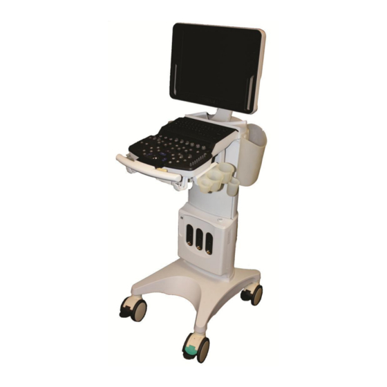
System Overview SYSTEM OVERVIEW Major System Assemblies Speakers 17” Display User Interface Cable management Storage Bins Hooks Gel Bottle Holder/ Transducer holders 2 USB ports Control Panel Height Adjust Left front wheel (black) And rear wheels – Wheel lock Power Button Multi-Transducer Port (MTP) Right Front Wheel (Green) -
Page 30: User Interface Overview
User Interface Overview Figure 1.1 - z.one Full Featured User Interface is shown above. Figure 1.2 - z.one Special Procedures (SP) User Interface is shown above. z.one Service Manual Page 30 of 217... - Page 31 5.1.1 USER INTERFACE FUNCTIONS Note: Not all controls are available on the SP user interface. Features and functions not directly accessible via hard key are still available however, via menus. System Control Description Setup Used to bring up the SYSTEM SETUP configuration menu F1 –F4 Function keys, user configurable in System Setup menu M-mode...
- Page 32 FREQUENCY Enables increasing/decreasing transmit frequency Menu Press to display menu list. STORE2 Press to store the displayed image to the alternate storage device. STORE1 Press to store the displayed image to the primary storage device. “SET” Used to toggle the function of active items on display FREEZE Halts or re-starts active imaging on the display OPTIMIZE...
- Page 33 Undo (Calc) Deletes active Calculation tool from the display REPORT (Calc) Brings up the Calculation report page Trackball Used for positioning the cursor, defining size/position of ROI in color mode, positioning measurement tools, reviewing cine-loop images and navigating form/tables/worksheets/reports HARMONICS Activates tissue harmonics imaging mode DGC Slide pots Changes gain of image at discrete depths PRINT...
-
Page 34: Keyboard Functions
Keyboard Functions Figure 2: z.one keyboard keys and function KEYBOARD: SPECIAL FUNCTION CONTROLS System Control Description This is a toggle key. The first press will display the Patient Information page. NEW PATIENT The second press will return to the imaging display. If there is an exam in progress, pressing this key will display the in-progress CURRENT EXAM exam's images, most recently stored image displayed first. - Page 35 System Control Description This key only works when in in-progress exam review or archived exam review. Pressing this key will toggle between the following image formats: 2 x 2, FORMAT displaying 2 rows of 2 images (4 images); 3 x 2, displaying 2 rows of 3 images (6 images);...
-
Page 36: On-Screen "Dashboard" System Status Icons
On-Screen “Dashboard” System Status ICONs If the system is equipped with the on-board battery option, a battery icon will be displayed in the upper- left hand corner of the LCD display of the z.one Icon Function Status Description Battery Status System running on AC Power, and Battery is fully charged. - Page 37 Icon Function Status Description DVD Media DVD media inserted, but not available for image storage DVD Media DVD media inserted and is available for image storage DVD Media Image storage to DVD media is occurring DVD Media DVD is inserted but is FULL Removable Removable storage media (USB) is being initialized Media (USB)
- Page 38 Icon Function Status Description Network Network connected and active Network Network disconnected Network Network transfer has an error (Re-Queuing of job, etc) preventing transfer Wireless Wireless network connected and active Network Wireless Wireless Network disconnected Network Wireless Wireless Network transfer has an error (Re-Queuing of job, Network etc) preventing transfer Wireless signal strength: 1% –...
-
Page 39: Accessory Components
They have been verified for optimum reliability and performance. If you purchase your own USB memory stick, ZONARE is not responsible for any errors associated with file corruption or file-transfer time increases. For a list of USB memory sticks approved by ZONARE, go to www.zonare.com/support/accessories. -
Page 40: Rear I/O Panel
Rear I/O Panel Figure 3: Rear I/O Panel 5.1.2 FUNCTIONS: I/O CONNECTORS Function Direction Ethernet 10/100BaseT - (Network) Input/Output Serial Port - eSATAp Input/Output USB Port Input/Output HDMI Connector (video and audio) Input/Output z.one Service Manual Page 40 of 217... -
Page 41: System Uncrating & Installation Procedures - Update Entire Section
If any problems are found, make notes of any discrepancies and immediately report to the shipping carrier and to ZONARE’s shipping department representative. All installation and set-up of equipment should be done following this official ZONARE product installation procedure. -
Page 42: Figure 1: Main Shipping Container Removal
Figure 1: Main shipping container removal 9. Remove the clear packing tape that is used to secure the foldable wooden loading ramp in its upward- facing shipping position. Lower the ramp on its hinges. Figure 2: Loading ramp lowering 10. Remove the clear packing tape that secures the front support to the base during shipping. Grasp the removable front support section of the wooden shipping base (at the bottom-front of the system), pull it directly outwards away from the z.one system, and set aside. -
Page 43: Figure 4: Removing Protective Storage Bag
Figure 4: Removing protective storage bag 12. Locate the left front caster on the z.one and press down on the upper black tabs to release the break. (Figure 8.2). You can leave the directional lock caster as is (right front/green) Figure 5.1 &... -
Page 44: Mechanical Inspection
Ensure the LCD display monitor rotates and adjusts properly Ensure the z.one module is securely attached in the Cart. Immediately report any mechanical discrepancies to ZONARE. z.one Service Manual Page 44 of 217... -
Page 45: System Installation
System Installation ZONARE MODULE COVER INSTRUCTIONS WARNING Ensure system is powered OFF. Place AC circuit breaker, located at the rear of the cart in the off “0” position. Disconnect the main AC power cord from the rear of the cart or unplug from the wall source. -
Page 46: Z.one System Verification
Check to ensure all peripherals, software level, and serial numbers correspond with sales order. Make note of any missing items or discrepancies, and immediately report to ZONARE. WARNING To prevent possible damage to the electronics of the system from condensation, the following... - Page 47 Verify the socket of the AC power cord is fully inserted into the inlet in the back of the cart. Connect the plug of the AC power cord into a Hospital Grade receptacle. System is in the “1” (ON, pushed in on the LEFT) Make sure the AC Main Circuit Breaker on the z.one position (see illustration below).
- Page 48 Test and Verify USB Peripheral Connectivity and Functionality (if applicable) 7. Verification is complete – return system to normal operation. z.one Service Manual Page 48 of 217...
-
Page 49: Basic System Configuration
BASIC SYSTEM CONFIGURATION Entering “Institution” Name 1. Press the “SETUP” key on the User Interface and use the trackball to select Tools menu. TOOLS Menu 2. Using the trackball to backlight SYSTEM SETUP selection, and press one of the SET keys bring up this menu. -
Page 50: Configuring "Barcode" Scanner
DISPLAY Sub-Menu INSTITUTION Sub-Menu 4. Using the alpha-numeric keyboard, enter Institution name (Note: Field is limited to 20 character positions) 5. Place the arrow cursor over the APPLY soft-button displayed in this menu, and press one of the SET keys to save new settings. -
Page 51: Configuring "Audio/Video
Operator ID 3. If the system is setup to interface with a DICOM Worklist server for populating patient exam scheduling, check the “Worklist Cache” option , within the Barcode Worklist Option selection. Enabling this option will result in the system using the scanned-in barcode parameter (Patient ID, Accession Number, or Operator ID) for identifying the patient, to reference the cached Worklist data for auto-populating various fields in the Patient Information page. -
Page 52: Entering "Time/Region" Information
matching the target peripheral device (external DVI monitor, etc). The two external video format options available are: Standard: 1280 x 1024 format (entire screen of z.one Image Only: 800 x 600 format (image area only) 4. Once all the desired values have been selected, place the arrow cursor over the APPLY soft-button displayed in this menu, and press one of the SET keys to save new settings. -
Page 53: Entering "Trackball" Configuration
Entering “Trackball” Configuration 1. Within the Display selection, use the Menu Control to backlight Trackball selection, press one of the SET keys to bring up this menu. DISPLAY Sub-Menu TRACKBALL Sub-Menu Cine Trackball Configuration: This menu allows for configuring the behavior of the trackball to users preferences, independently for a variety of Cine modes. -
Page 54: Configuring "Imaging" Parameters
Strip Cine Trackball: (M-Mode or Spectral Doppler modes) Description: Controls the rate at which the time axis sweep is advanced in response to each sweep of trackball movement by the User. Cursor Sensitivity Strip Cursor: (PW/CW Doppler modes) Description: Controls the sensitivity of the movement of the PW cursor line, via trackball movement by the User. - Page 55 1. For each Transducer type in the pull-down menu, configure the power-up default application type and preset type that are desired. 2. Select the desired behaviors to occur post transducer change: Preserve Exam & Preset If checked, the system will retain the current Exam Type and Preset, when transitioning to selection of a different active transducer.
-
Page 56: Archive Menu Functions
ARCHIVE MENU FUNCTIONS “Media” & “Store/Print” Setup 1. Using the TAB button advance the menu screen to select TOOLS 2. Using the Menu Control, arrow down to backlight the Archive selection, and press one of the SET keys to bring up this menu. SYSTEM SETUP Sub-Menu ARCHIVE... - Page 57 “MEDIA” CONFIGURATION 1. Within the ARCHIVE selection, use the trackball to backlight Media selection, press one of the SET keys to bring up this menu. ARCHIVE Sub-Menu STORAGE MEDIA Sub-Menu 2. Make any changes desired to the settings for still and clip image compression, and defined modality. In most cases using the factory default settings will perform well on a customer system.
- Page 58 “STORE/PRINT” BUTTON CONFIGURATION 1. Within the ARCHIVE menu, use the Menu Control to backlight Store/Print selection, press one of the SET keys to bring up this menu. ARCHIVE Sub-Menu IMAGE STORE/PRINT BUTTONS Sub-Menu 2. Based upon what functions are desired to occur when the PRINT and STORE buttons on the are pressed, configure the settings in this menu.
-
Page 59: Exam Export" Options
Exam in Progress: Results in each new DICOM image immediately being placed into the DICOM Queue for transfer to the target network/print device, each time the corresponding STORE/PRINT key is depressed. Exam Completed: Images are buffered during each STORE key depression, and later placed as a group into the DICOM Queue for network/print transfer. -
Page 60: Exam Management" Setup
EXAM EXPORT Sub-Menu 8. Configure the Exam Export Options settings to reflect the desired formatting for the target images upon export. 9. To save the new settings, select APPLY from the main menu, and press one of the SET keys save new settings. - Page 61 EXAM MGMT Sub-Menu 3. Configure the “Exams are Restarted Using” selection to reflect the desired grouping of images upon restarting of a previous exam on the Customer’s system. Prior Series: Appends new images onto the series of images previously captured. IMPORTANT “Prior Series”...
- Page 62 stored) will only be retained in post-rebuilt exam, if the “READ” option for the Helper files is “unchecked”. Rebuild Patient Exam Database - Content: This option allow for specifying the granularity of the exam database rebuild process that is initiated with the “REBUILD”...
- Page 63 WARNING Initiating the “ERASE” function will completely delete ALL patient exams (all stored images) on the internal ARCHIVE storage. DO NOT perform this function unless the system’s User has confirmed that all needed exams/images have been exported/transferred to another medium, or are no longer needed. Due to this operation performing individual “deletes”, the “ERASE”...
- Page 64 Full: ......Comprehensive screening of target media device (longer) -------------------------------------------------------------------------------------------------------------------------- Study Description Option: Auto Update The “Auto Update” option being selected results in the “Study Description” field (DICOM Tag: 0008,1030), on the Patient Demographics page, being automatically populated with source information provided from the DICOM Worklist server (if info is provided).
-
Page 65: Archive "Export" Options
Non-DICOM: Exam data stored on output target device in a non-DICOM (cannot be re-imported or viewed on ZONARE) format, as selected in non-DICOM export option area. Hard Drive Verify Options: Minimum: Basic level checksum verification only (fastest) ... -
Page 66: Serial Port" Setup - (Export Calc Report Data)
IMPORTANT For use of DVD media type for Exports, only one brand/model of DVD media has been tested and approved to be compatible for use with the ZONARE system. The approved DVD media type is as listed below: Taiyo Yuden brand DVD media ONLY! “Serial Port”... - Page 67 The three (3) types of Calc report data that can be exported, via the USB ports, are as listed below. Configuring which report type(s) will be exported is performed on the SYSTEM SETUP ->CALCS -> EXPORT/PRINT menu. OB/GYN Calc Output ...
- Page 68 SERIAL PORT Sub-Menu 3. If desired, check the box to select the USB port as the target for EXPORT function of OB/GYN report data. 4. If desired for report data to be exported in sync with DICOM image transfers to the PACS system over the network, check the box for “Link Serial Connect to Ethernet Connect”.
-
Page 69: Dicom Configuration
Prior to system installation at any medical facility utilizing a DICOM network environment, a “Pre-Install Survey Form” (ZONARE P/N: F00044) should have been completed. This form is used for obtaining, in advance, detailed networking and DICOM configuration values (IP addresses, AE Titles, etc.) from the IT/PACS System Administrator at the facility. -
Page 70: Parameter Definitions
Parameter Definitions The table below provides some guidance regarding the type of information required for the DICOM configuration of the various menus (“General”, “Printers”, Network Store”, “MPPS” and “Worklist”) on the system. DICOM Configuration Definition: Parameters: AE Title The official “name” (Application Entity) assigned to system (by the network e.g., “Zonare1”... - Page 71 DICOM Configuration Definition: Parameters: Limit by Modality Filtering by modality (US, CT, MRI, et cetera) of scheduled patient examination data generated by the Worklist server. Set according to department requirements. None None: Show entries for all modalities. US (ultrasound) US: Show entries for ultrasound exams only.
- Page 72 DICOM target devices. Scheduled Station AE Title Identity (Application Entity Title) assigned to the ZONARE ultrasound system, for use in filtering patient exam scheduling data provided by the Worklist server. Value to be provided by PACs Admin, to meet department requirements.
-
Page 73: Pre-Install Survey Form
Password: _____________________ General System / DICOM Setup Parameters Level Parameter Name User Site Value/Setting Default / Special Info Application (AE) Title – (Zonare System) User option ZONARE Station Name – (Zonare System) User option ZONARE User option TCP Timeout (sec.) User option Queue Timeout (sec.) - Page 74 Level Parameter Name User Site Value/Setting Default / Special Info User option Max PDU Receive Size 16384 User option Max PDU Send Size 16384 User option Color Mode Color Grayscale Color User option Number of Copies High User option Print Priority Selections: (2x2, 1x1, 1x2, 2x1, 2x3, 3x2, User option Image Display Format...
- Page 75 Level Parameter Name User Site Value/Setting Default / Special Info User option Reconciliation Reconcile patient/exam information unchecked - Rewrites Patient Info into all images in exam, based on last frame stored, prior to re- send to PACS User option Object Type Still/Single-Frame Image Always checked (grayed) Cine/Multi-Frame Image...
- Page 76 Level Parameter Name User Site Value/Setting Default / Special Info User option Maximum Entries Cached User option Filter Cached Entries Filter Cached Entries On (checked) User option Query on Display Query on Display Off (unchecked) Media – Storage Setup Parameters Level Parameter Name User Site Value/Setting...
-
Page 77: Dicom" Configuration Procedure - Menus
“DICOM” Configuration Procedure - Menus Refer to the “Survey Form” (on the previous pages), for detailed information of all the values that NOTE: are offered in the z.one menus, for selection within the various fields, in each of the following configuration screens. - Page 78 Using the trackball and scroll down to backlight SYSTEM SETUP selection, and press one of the SET keys to bring up the main menu, then select the ARCHIVE option, followed by the LOCATION option. SYSTEM SETUP Sub-Menu ARCHIVE Sub-Menu Within the Location selection, use the Menu Control to backlight selection, and press one of Manage the SET keys...
- Page 79 Enter in the desired user-defined name to be used for the new “Location” To save the new Location, select APPLY from the main menu, and press one of the SET keys Open each of the configuration pages (Network, DICOM General, etc) for parameters that are savable under the Location manager, and enter in the desired settings.
- Page 80 SYSTEM SETUP Sub-Menu DICOM Sub-Menu Within the DICOM selection, use the Menu Control to backlight selection, and press the GENERAL SELECT button to bring up this menu. DICOM Sub-Menu DICOM GENERAL Sub-Menu Using the alpha-numeric keyboard, enter in the required DICOM configuration values/settings in the appropriate fields, as specified in the information previously provided in the “Pre-Installation Site Survey Form”, by the medical facility’s IT System Administrator.
- Page 81 DICOM “PRINTERS” CONFIGURATION 1. Within the DICOM selection, use the Menu Control to backlight selection, and press one PRINTERS of the SET keys to bring up the DICOM Printer Administration menu. DICOM Sub-Menu PRINTER Administration Sub-Menu 2. To create an entry for a new printer to be added to the DICOM connectivity for the z.one , use the Menu Control to backlight from the main menu, and press one of the SET keys...
- Page 82 3. Using the alpha-numeric keyboard, enter in the DICOM configuration values/setting in the appropriate fields, as specified in the information previously provided in the “Pre-Installation Site Survey Form”, by the medical facility’s IT System Administrator. 4. To save the new settings, select APPLY from the main menu, and press one of the SET keys save new settings.
- Page 83 4. To save the new settings, select APPLY from the main menu, and press one of the SET keys save new settings. DICOM” MPPS” (MODALITY PERFORMED PROCEDURE STEP) CONFIGURATION 1. Within the DICOM selection, use the Menu Control to backlight MPPS (Modality Performed Procedure Step) selection, press Select button to bring up this menu.
- Page 84 DICOM” WORKLIST” CONFIGURATION 1. Within the DICOM selection, use the Menu Control to backlight Worklist selection, press Select button to bring up this menu. DICOM Sub-Menu DICOM WORKLIST CONFIG Sub-Menu 2. Using the alpha-numeric keyboard, enter in the DICOM worklist values/setting in the appropriate fields, as specified in the information previously provided in the “Pre-Installation Site Survey Form”, by the medical facility’s IT System Administrator.
-
Page 85: Network" Setup
“Network” Setup The “NETWORK” configuration menu allows for configuring the TCP/IP networking parameters that will be assigned to define the identity of the system on the hospital’s network. 1. Use the Setup button and trackball to advance menu screen to select TOOLS menu, then select SYSTEM SETUP. -
Page 86: Ftp" Setup
Quatech AirborneDirect device that is connected to the Ethernet port on the ZONARE system, it will require 30 to 60 seconds to detect and then associate with the user's wireless network. Once a wireless network connection is established, the ZONARE system will reflect the connection state by showing the network ICON on screen, in an uncrossed state. - Page 87 Using the trackball scroll down to backlight ARCHIVE selection, and press one of the SET keys bring up this menu. Using the trackball scroll down to backlight selection, and press one of the SET keys to bring up this menu. FTP Store selection, and press one of the SET keys Using the trackball scroll down to backlight...
- Page 88 Using the trackball scroll down to backlight Apply selection in the main menu, and press one of the SET keys to save the serial port configuration setup, and exit. z.one Service Manual Page 88 of 217...
-
Page 89: Advanced System Setup Configuration
ADVANCED SYSTEM SETUP CONFIGURATION “Security” Setup Menus If the security password is lost or forgotten, there is NO master password available to Warning recover system access. To restore use of the system, it will be necessary to perform a complete re-installation of system software. -
Page 90: Power Save" Setup Menu
Under the Logon Password field, enter in the desired security access password. (NOTE: You will need to enter it in a second time in the “CONFIRM” field, to ensure accuracy). To save the new Security settings, select Apply on the main menu, and exit. “Power Save”... - Page 91 running off the z.one ’s internal Z-PAK battery. External Power Configuration of power saving action when the system is running off AC wall power The two configurable Power Save behaviors offered are: Title Function Sleep when idle Screen display is “Blanked”, after configured time period has elapsed System performs a complete sequenced “Power-Down”...
-
Page 92: Functional Descriptions
FUNCTIONAL DESCRIPTIONS System Capabilities 64-hardware - 128/192-synthetic channel system Supports B-Mode, M-Mode, Color, Power Doppler, PW 17” full-screen, 1280 x 1024 resolution, Display Full-sized alpha-numeric user keyboard Discrete function user controls Software mode assignable user controls ... - Page 93 11.1.2 USER INTERFACE ASSY, Z.ONE P/N: 86700-00 (86702-00 FOR SP VERSION) QWERTY keyboard OLED soft-function displays Trackball assembly DGC controls Discrete functional controls 11.1.3 DISPLAY, Z.ONE P/N: 89051-00 System display Speakers 11.1.4 ELECTRO AND MECHANICAL ASSEMBLIES 11.1.5 BRAKE MECHANISM - WHEEL The system has 2 different types of casters.
-
Page 94: Figure 6.1: Directional / Swivel Caster Figure 7.2: (X3) Breaking Caster
Press lower tab to lock and press upper tab to release break/direction feature. Figure 6.1: Directional/swivel Caster Figure 7.2: (X3) Breaking Caster 11.1.6 HEIGHT ADJUSTMENT MECHANISM The system utilizes a gas spring mechanism that enables the user to optimize the vertical position (height) of the user interface panel and LCD Display for optimum comfort and viewing during operation. -
Page 95: System Diagrams
SYSTEM DIAGRAMS BEGINS ON NEXT PAGE z.one Service Manual Page 95 of 217... -
Page 96: Power Block Diagram
Power Block Diagram Figure 21: Power Block Diagram z.one Service Manual Page 96 of 217... -
Page 97: Cabling Diagram
Cabling Diagram z.one Service Manual Page 97 of 217... -
Page 98: System Block Diagram
Figure 22: Cabling Diagram System Block Diagram Figure 23: Overall System Block Diagram z.one Service Manual Page 98 of 217... -
Page 99: Peripherals & Accessories
IMPORTANT For use of DVD media type for Exports, only one brand of DVD media has been tested and approved to be compatible for use with the ZONARE system. The approved DVD media type is Taiyo Yuden brand. Before deleting any exam data from the system, always verify that the data was successfully transferred to the CD/DVD by viewing it on an external reader/player. - Page 100 In order to eject this type of incompatible media, it will be necessary to perform a manual override “EJECT”. This is accomplished by holding down the “RECORD” button on the user interface panel of the z.one , until the DVD/CD is ejected. 13.1.2 OPERATION The exporting/importing of exam data (images) to/from the DVD/CD burner on the z.one performed in the ARCHIVE review menu (pressing the ARCHIVE key).
-
Page 101: Black & White Printer
Black & White Printer The procedure provides instructions to install and setup the SONY UP-D711 Black and White printer on the z.one system Prior to beginning the initial mounting/installation, ensure the system is powered-down (Backlight for On/Off button will be dark.). 13.1.3 UNPACKING AND MOUNTING INSTRUCTIONS 1. -
Page 102: Figure 10: Printer Bracket Mounting To Z.one
3. Use a Philips screwdriver to install the four (4) 33104-00 screws that attach the printer/bracket assembly to the user interface base. Threaded holes are in the UI casting on each side of the DVD assembly (as shown below). Figure 10: Printer Bracket Mounting to z.one Cart NOTE: The printer comes out of the box with M3 Phillips head screws installed in its threaded mounting holes, as placeholders or thread protectors. - Page 103 Slide printer forward to its mounting position in the bracket. (Mounting holes in bracket will align with threaded holes in bottom of printer – in centers of round pads. Top front printer corners will be approximately in alignment with the lower front surface of the DVD cover, as shown below).
- Page 104 Dress printer cables up inside the printer bracket and secure with the cable-tie (30133), as shown below Page 104 of 217 z.one Service Manual...
-
Page 105: Figure 12: Operator Controls (Up-D711)
13.1.4 OPERATOR CONTROLS Figure 12: Operator Controls (UP-D711) Power ON/OFF Switch Printer Lamp – Lights while printing Feed Button – Hold down to feed paper. The paper will only advance while the button is pressed. Paper Lamp – Lights when tray is empty or paper not aligned correctly. Alarm Lamp –... - Page 106 13.1.5 SETUP PROCEDURE 1. Connect the USB cable with the symbol facing up into the back of the printer. 2. Connect the DC power cable in to the back of the printer. 3. Power-On the system. 4. Turn the printer on by pressing the button.
- Page 107 7. Make sure the paper is set straight. 9. Close the door and press until it locks. 13.1.6 SETUP PROCEDURE 1. Access the New Printer menu, using the path System Setup->Archive->DICOM->Printers->New Page 107 of 217 z.one Service Manual...
- Page 108 2. Using the pull-down menu, under the “TYPE” selection, select the USB printer. The menu will change to the limited setup page for a USB style printer (as shown below) 3. Type into the “Nick Name” field, the name of the printer: “SONY UP-D711” 4.
- Page 109 2. Under the “Network/USB Printer” function for the “Print” button, check the box to the left of the drop-down menu, enable this function 3. In the drop-down menu for this function, select the “SONY UP-D711” selection 4. Select “APPLY” from the main menu, to save the changed settings 13.1.8 PRINT VERIFICATION: 1.
-
Page 110: Color Printer
Color Printer 13.1.9 INSTALLATION NOTES: SPECIAL NOTE The Sony UP-D25MD Color Printer is oversize and is therefore not a peripheral that can be “mounted” on z.one system. A separate external location (rolling cart, tabletop, etc) must be made available for storage of this printer. The system software on the z.one system contains the necessary drivers to support operation and printing to the Sony UP-D23MD and UP-D25MD Color Printers. -
Page 111: Network Report Printer
Network Report Printer 13.1.11 PROCEDURE NOTES: The intent of this procedure is to provide instructions, for use in the field, for setup and use of a Post Script-3, PS3 (or above) style, HP LaserJet Network Printer, for OB, Vascular, or Cardiac Report printing, on the system. - Page 112 2. Connect one end of the network crossover cable to the HP LaserJet printer, and the other end to the Ethernet (RJ-45) port on the system. 3. Power on the HP LaserJet printer 4. Open the paper tray on the printer, and install the desired paper. 5.
- Page 113 NETWORK Installations Only: To meet regulatory requirements for user safety, Ethernet “Network” connectivity is the only method recommended for attaching the HP LaserJet printer to the system. In this configuration a direct cable connection will be used between the printer and the z.one (using a “crossover cable”).
- Page 114 Network Configuration Page 2. Using the arrow cursor and SET key, check the box for “USE SPECIFIED” 3. In the data entry box to the right of the “USE SPECIFIED” checkbox, enter in an IP Address that is one greater then the value of the HP LaserJet printer (i.e printer: 192.168.1.1, z.one 192.168.1.2) 4.
- Page 115 SYSTEM SETUP Sub-Menu Using the trackball scroll down to backlight the Keys selection, and press one of the SET keys to bring up the configuration menu. For the desired Function Key (F1 – F4) selection, select the MICROPHONE function from the pull-down menu To save the Function Key assignment, select APPLY from the main menu, and press one of the SET keys...
-
Page 116: Pedal Footswitch
Pedal Footswitch A remote 2-pedal footswitch is optionally available for connection to the system via any available USB port. The left and right pedals may be individually configured to one of forty-four possiblilities including Freeze and Store . The two normal user interface buttons/functions used for the optional footswitch control; are as follows: o FREEZE o STORE... -
Page 117: Software Procedures
SOFTWARE PROCEDURES Backup Operations Backing up customized User “Presets” and “System” settings: 1. If there are customized User “Presets” and/or customized User “System” settings that are desired to be backed up, insert a target USB stick for backup into the USB port on the front or rear of the system. -
Page 118: Restore Operations
RESTORE Operations: 1. With the same USB stick still inserted, go to the Setup “PRESET ADMIN” menu and perform the “RESTORE PRESETS” and “RESTORE SYSTEM” operations. 2. The restore operations (in 5.0 > SW) provide capability for selecting the granularity for the specific parameters that will (or will not) be used during the Restore operations. - Page 119 RESTORE SYSTEM: The selectable options for the “RESTORE SYSTEM” operation, and a description of what parameters are included in each item, are listed below: Annotation/Body Patterns: User Annotation and customer Body Markers Calculation Setup: User Calculation setup parameters ...
-
Page 120: Standard Software Installation Procedure
Standard Software Installation Procedure 1. Connect a transducer to the system (if not currently attached) 2. Press the Power On/Off button to power the system on 3. Allow the system to complete a normal boot operation (less then 1 minute) 4. - Page 121 NOTE: The main application install process should complete in approximately 5 minutes. 11. After file installation is completed, the system will run a brief install verification process. The following screen will appear during this verification 12. At the completion of a successful software installation/verification process, a dialogue box with the following message should appear on the LCD Display screen 13.
-
Page 122: Clean" Software Install Procedure
“Clean” Software Install Procedure 1. Press the Power On/Off button to power the system on 2. Allow the system to complete a normal boot operation (less then 1 minute) 3. Insert the USB Memory Stick (containing system software installer files) into any one of the four USB ports at the rear of the z.one , pressing lightly to ensure it is seated in the connector 4. -
Page 123: Zonare Ftp Site
This tool is intended to allow direct access for downloading of file provided by ZONARE Tech Support, (like downloads of new System Software). The site is also provides space for uploading files to ZONARE Tech Support (i.e. image files for review). - Page 124 A single short press activates the User Diagnostics Panel. A long press (1 sec.) stores the current logs; the system beeps as logs are stored. An extended press (> 3 sec.) will initiate an immediate manual capture of the system error logs. 2.
- Page 125 ZONARE’s network server for uploading or downloading connection between the z.one files. Performing any of these procedures requires contacting ZONARE Technical Support to received specific information on IP address and log in used to make the connection. The features in the User Diagnostics Panel are described...
- Page 126 Check FTP for latest available software. Software Updates If new version available, then option to download to USB media from FTP site. Firmware Updates Check for firmware updates for cart assemblies Press Maintenance button to perform available updates. ...
- Page 127 Software Upgrade Options FTP Address 12.40.200.87, user name 50 SW and password support are supplied by ZONARE. Click Ping button to test connectivity to software folder on FTP site. Select the Auto notify of software updates to check FTP server for the latest software revisions and then select the number of days until next check.
- Page 128 You can select daily, every xx weeks on yy day of the week. Select Auto Logging Time to have logs automatically sent at a certain time of day. Select Error Logging to have logs automatically sent when error occurs.
- Page 129 VWALL: 24V +/- 5% (only when AC present) Battery Voltage: 14 – 21V Battery Temperature: 27° C / 0 to 45° C Charging State: OFF ------------------------------------- 0 SOFT_START ------------------------ 1 TOP_OFF ----------------------------- 2 RAPID_CHARGE ------------------- 3 TRICKLE ----------------------------- 4 MAINTENANCE -------------------- 5 RECONDITION ---------------------- 6...
- Page 130 Enables internal processes where on-screen warning Monitor Memory Use messages are displayed, and/or a forced system restart is performed, if maximum available block size drops below certain thresholds. Memory status checking will occur at each of the following intervals/events: 1) Storing an image 2) Activating/Connecting a transducer 3) Starting or Ending an exam...
- Page 131 Total: Total available memory size in scanner (in Used: Total currently used memory size in scanner (in MB) MaxBlock: Largest memory block size (in MB) Enable Debug Console Allows (if checked) or disables (if unchecked) access to the System Console window (ALT-GR / Shift / Z keys) for entering low-level commands for service.
-
Page 132: System Maintenance
Do not immerse the battery in water or allow it to get wet. Do not put the battery into a microwave oven or pressurized container. Use only ZONARE batteries. Store the battery between 32F and 120F (0 and 50C). -
Page 133: User Diagnostics Panel
ZONARE’s network server for uploading or downloading connection between the z.one files. Performing any of these procedures requires contacting ZONARE Technical Support to received specific information on IP address and log in used to make the connection. The features in the User Diagnostics Panel are described Page 133 of 217 z.one... - Page 134 Parameter Description System area The current software revision and system serial number appear here. Click the Details button for PC board revision information. Check FTP for latest available software. Software Updates If new version available, then option to download to USB media from FTP site.
- Page 135 Export logs to USB memory stick or other external media Clear log files from disk Manually push error logs to FTP server Page 135 of 217 z.one Service Manual...
-
Page 136: (Exam) Preset Mgmt/System Setup
To access the User Diagnostic Panel 1. While viewing an imaging display, press the Service key on the QWERTY keyboard: A single short press activates the User Diagnostics Panel. A long press (1 sec.) stores the current logs; the system beeps as logs are stored. ... - Page 137 2. Insert the presets/system backup removable media into the USB port at the rear of the z.one system. 3. When a popup window appears saying Install media detected. Do you wish to install new software? highlight No and press one of the SET keys 4.
-
Page 138: Software Upgrade/Installation
Calcs. Software Upgrade/Installation ZONARE periodically releases new software for your system. The upgrade procedure is easy and you can do it yourself. Total installation time is approximately 15 minutes. The method for accessing system software upgrades for installation at a user site is directly dependent upon the network and computer equipment present at the site. -
Page 139: Installing System Software
Quickly press the Service key on the QWERTY keyboard. Go to Setup button | System Setup | Diagnostics. Go to System Setup | Diagnostics. Installing System Software To Install System Software 1. Power on the z.one system 2. - Page 140 Cloth with thread made of steel Other coarse tools Do not autoclave, immerse, or attempt to sterilize the LCD display. To Clean Front Glass 1. Before cleaning, turn off the AC circuit breaker on the z.one system to remove all power from the unit.
- Page 141 After each use, remove and dispose of any used cover/sheath. Wipe off any excess gel from the transducer and clean it properly. Air dry the z.one system. WARNING: To avoid electrical shock before cleaning the z.one system, turn off the AC circuit breaker at the rear of the system.
-
Page 142: Transducer Maintenance
Be sure to check pins before connecting transducer to the z.one system. If pins are bent, broken, or missing, do not use the transducer and call ZONARE Technical Support. 15.1.1 INSPECTING TRANSDUCERS Inspect transducers at least weekly for signs of wear or damage. - Page 143 Endocavity probes: Mindray recommends performing the Immersion Method of disinfection after each patient exam. The use of a soft cloth thoroughly moistened with an approved disinfectant is recommended for cleaning the strain relief, transducer housing and cable. NOTE: The transducers cannot be sterilized. When sterility is required, use a sterile transducer cover/sheath and sterile ultrasound/coupling transducer gel.
- Page 144 IMMERSION METHOD NOTE: all Transducers may be immersed except for the Aux CW transducer. Disconnect the transducer from the system. If present, remove the transducer cover/sheath and discard. Use a soft cloth dampened with mild soap (Liquinox) and water solution to remove particulate, ultrasound coupling gel, or body fluids.
-
Page 145: Figure 13: Transducer Immersion Limits
Figure 13: Transducer immersion limits 15.1.4 ZONARE-APPROVED TRANSDUCER DISINFECTANTS NOTE: For the latest list of transducer disinfectants approved by ZONARE, go to http://www.zonare.com/support/care or refer to Page 145 of 217 z.one Service Manual... -
Page 146: System Troubleshooting
FRU’s (Field Replaceable Units). Technical Support Contact Information ZONARE Contact Information SHENZHEN MINDRAY BIO-MEDICAL ELECTRONICS CO., LTD. Mindray Building, Keji 12th Road South, High-Tech Industrial Park, Nanshan, Shenzhen, 518057,P.R.China... -
Page 147: Troubleshooting
Caution: Bent, broken, or missing pins on the transducer connector may cause poor image quality, including possible mirror image artifact. Be sure to check pins before connecting transducer to the ZONARE ultrasound system. If pins are bent, broken, or missing, do not use the transducer and call ZONARE Technical Support. - Page 148 STATUS Definition Solid: System has AC Mains applied and 5V standby is active. “AC Present” OFF: No AC detected, circuit breaker off OFF: No battery installed, or completely depleted Blinking: Battery charging (or reconditioning) in- “Battery” process Solid: Battery is fully charged “Controller Solid: uCPU is up Status”...
- Page 149 6. If either component fails to start up after these steps, contact Mindray Tech Support. 16.1.2 PERIPHERAL PROBLEMS 17” Display monitor, no video Power down the system, then switch off circuit breaker (at rear of system) to remove power to system electronic.
- Page 150 ZONARE Technical Support If the printer fails to print after these steps, contact Mindray Tech Support. 16.1.3 TRANSDUCER PROBLEMS Transducer not recognized by system (no B-mode imaging) To ensure a positive connection, disconnect the transducer and reconnect it.
- Page 151 Unable to modify existing User Preset (grayed out) Make sure the desired user preset was previously (i.e., before attempting to modify it) selected as the active preset. System will not communicate with target DICOM” Store” or “Print” device ...
-
Page 152: System Status Led & Error Code Definitions
System Status LED & Error Code Definitions 16.1.6 REAR I/O PANEL – SYSTEM STATUS LAMPS The seven (7) system status indicator lamps located on rear of the system (panel just above the main AC circuit breaker) can be used to assist in troubleshooting problems with the system. The definition of the each lamp is as shown in the table below: STATUS Definition... - Page 153 16.1.7 SYSTEM ERROR MESSAGE CODES Error Code Subsystem Message for Error log User Error Message Action on Action NOTE: Various messages EUSCONTROL ostr.str() from function box 0xa00d0401 "Detected ADC Error. See 0xa00e0401 DIAGNOSTICS Detected Bad Channel In ADC Test. Logs for more errors." Continue "ADC Test Error In Setup: 0xa00e0402...
- Page 154 Error Code Subsystem Message for Error log User Error Message Action on Action THERMALSER XMT_V5NA over warning "System Overheat Warning: 0xaf050435 VICES Temperature Limit Finish exam and shutdown." Continue THERMALSER XMT_VSUPR over warning "System Overheat Warning: 0xaf050436 VICES Temperature Limit Finish exam and shutdown."...
- Page 155 Error Code Subsystem Message for Error log User Error Message Action on Action "Internal System Error has 0xe00a0405 IMAGING Failed to set HV limits to PIC occurred. " Restart "Internal System Error has 0xe00a0406 IMAGING Failed to set QDAC voltage to target occurred.
- Page 156 Error Code Subsystem Message for Error log User Error Message Action on Action "Internal System Error has 0xe00a0426 IMAGING HV0N Not in limits occurred. " Restart "Internal System Error has 0xe00a0427 IMAGING HV0P Not in limits occurred. " Restart "Internal System Error has 0xe00a0428 IMAGING HVCW Not in limits...
- Page 157 Error Code Subsystem Message for Error log User Error Message Action on Action VICES shutting down system." THERMALSER Exceeded maximum system error "System Temperature Limit 0xef050404 VICES count exceeded." Shutdown THERMALSER "Battery Temperature Limit 0xef050406 VICES Battery temperature error Exceeded. Replace battery." Shutdown THERMALSER "System Temperature Limit...
- Page 158 Error Code Subsystem Message for Error log User Error Message Action on Action VICES THERMALSER Received Temp Alert with unknown "System Temperature Limit 0xef05043d VICES error exceeded." Shutdown THERMALSER "Temperature Limit 0xef050440 VICES Failed to Set Temperature Limits Failure." Shutdown THERMALSER "System Temperature Sensor 0xef050450...
- Page 159 Error Code Subsystem Message for Error log User Error Message Action on Action VICES THERMALSER PWR_LV sensor communication "System Temperature Sensor 0xef050461 VICES error Communication Error." Shutdown THERMALSER PWR_TSUPR sensor communication "System Temperature Sensor 0xef050462 VICES error Communication Error." Shutdown THERMALSER DIG_HYDRA sensor communication "System Temperature Sensor...
- Page 160 Error Code Subsystem Message for Error log User Error Message Action on Action system." FRONT_END_ "Internal System Error has 0xef080401 POWER Low Voltage failure occurred occurred. " Shutdown FRONT_END_ "Internal System Error has 0xef080402 POWER Relay Voltage failure occurred occurred. " Shutdown FRONT_END_ "Internal System Error has...
-
Page 161: Battery Performance - Charge Times - Reconditioning
Error Code Subsystem Message for Error log User Error Message Action on Action "Software install failed. Software install failed. Please Re- Please Re-install the system 0xef100410 install the system software software." Restart "Software license expired. Software license expired. Please Re- Please Re-install the system 0xef100412 install the system software. - Page 162 Charging Fast Charge Rate (5A): ..................5.0 hours (total) Step #1: ......................... 3.0 hours – main charge Step #2: ......................... 2.0 hours – final top-off charge Trickle-Charge Rate (i.e., hot battery state) ............ 16.0 Hours (worst-case) Recondition & Full Charge State: Optimum (battery in cool state, and initial charge level near full) ....
-
Page 163: Replacement Procedures
REPLACEMENT PROCEDURES The procedures described in this section of the Service Manual should be performed ONLY by a ZONARE trained service personnel (Service Engineer, Biomed, etc.). Recommended Tools Tool Description Size Where used Screwdriver, flat blade, medium tip, std. length 3mm blade, 6”... -
Page 164: Z.one Module - Removal/Replacement
Module – Removal/Replacement z.one Identify the process for replacing the z.one Module. Overview of Procedure: Remove Cosmetic Cover Remove z.one Module Replace z.one Module Reassemble Cosmetic Cover Verification of System Parts Required: 88001-00 Module Equipment / Tools Required: ... - Page 165 Open Chassis Cosmetics: 1. Ensure the system is powered “OFF”. 2. Place AC circuit breaker, located at the rear of the cart, in the “OFF” position. 3. Disconnect the main AC power cord from the rear of the cart or unplug from the wall source. 4.
- Page 166 Replace z.one Module: 1. Align replacement z.one Module so that narrow end is on the bottom and top surface is below the convex plastic tab. 2. Push z.one Module into place. 3. Insert the clasps into the slots and tighten by turning the flaps clockwise. 4.
- Page 167 Verification of System: Reconnect the main AC power cord from the rear of the cart or plug into the wall source. Place AC circuit breaker, located at the rear of the cart, in the “ON” position. Ensure the system is docked. Energize the system.
-
Page 168: 17" Display - Removal/Replacement
17” Display – Removal/Replacement Required Parts 89051-00 Display Assy, z.one Overview of Procedure Removal of Display Assy Installation of Display Assy Verification of LCD Display & Speakers Required Tools/Equipment #1 Phillips Screwdriver Removal Procedure Ensure the system is powered “OFF”. Place AC circuit breaker, located at the rear of the system, in the “... -
Page 169: Figure 16: Display Cover Figure 21: Display Cover Removed
Figure 16: Display Cover Figure 21: Display Cover removed Remove the screws Power Video holding the cable retainers in place. Note: these retainers are not the same size. Power is slightly larger. Disconnect the two PWR and Video Cables cables by pulling down. (see below) Note: the power cable (left) has a locking connector which will have to Cable retaining screws... - Page 170 The display will drop slightly onto the brackets. There is a tab on each bracket that fits into the slot in the monitor to keep the display from falling. Carefully remove the monitor (see above) Set the display aside. Installation: Carefully place the display on the hinge brackets shown below.
- Page 171 3. Ensure the system is docked in the cart. 4. Energize the system. 5. Verify that the LCD display is functioning correctly by watching the boot and verifying that normal imaging is displayed after fully booted. 6. Attach a transducer (if not already connected) and enable PW mode. 7.
- Page 172 Cart Battery – Removal/Replacement Required Parts P/N: 85031-00 Assy, Battery Pack, Gen II Cart Required Tools/Equipment #2 Phillips Screwdriver 4mm Hex Key Overview of Procedure Removal Battery Pack Re-installation of Battery Pack Verification of system operation Battery Pack Removal: Place AC circuit breaker, located at the rear of the system, in the “OFF”...
- Page 173 Remove Second Remove First Loosen Remove the larger screw, located on the right side of the mounting of the Battery Pack to the bottom of the system (leaving the last two (2) screws, on the left side of the battery pack, still in place). Slightly loosen (but DO NOT REMOVE) the remaining two (2) large screws (on the left side of the battery pack), while supporting the weight of the battery pack with your hand.
- Page 174 Battery Pack Re-Installation: Insure the main AC power cord to the rear of the system is NOT connected to wall source. While holding the battery pack in position, plug the power connector into the receptacle on the bottom of the power supply. While still supporting the weight of the battery pack attach the power cable to the mating connector on the bottom side of the power supply module on the system.
- Page 175 b. B. Flip the cart circuit breaker “on” by pushing in the “1”. System Verification: 1. Power on the system and perform a series of basic user operations, to verify normal system functionality. 2. Verify that the battery status ICON, on the upper-left corner of the display of the system, shows a current status.
-
Page 176: Power Module - Removal/Replacement
Power Module – Removal/Replacement Required Parts P/N: 88012-00 ..Power Supply Module Overview of Procedure Removal/Replacement of Power Supply Module System verification Required Tools • 4mm Allen Head Wrench #1 Phillips Screwdriver Procedure Power Supply Module Removal: 1. - Page 177 Remove six (6) of the eight (8) mounting screws as shown below. 8. Partially remove the lower two (2) mounting screws retaining the power module to the bottom of the system and allow them to help support supply while the cables are being disconnected. 9.
- Page 178 10. Reach in and disconnect the five (5) cable connections. Note where each cable connects for reassembly (see figure for assistance). NOTE: The cables marked above have a locking connector. You need to grasp the hood and slide towards you before pulling connector to disconnect. 11.
- Page 179 Installation: 1. Reconnect the cables to the replacement Power Supply Module. 2. Tuck cables back into chassis and position Power Supply Module for installation. 3. Reinstall the eight (8) screws. Ensure that the Power Supply Module is securely connected. 4. Reattach the AC power cord to the socket at the rear of the Power Supply Module. 5.
-
Page 180: User Interface - Removal/Replacement
3. Verify that the LCD display is functioning correctly by watching the boot and verifying that normal imaging is displayed after fully booted. 4. Attach a transducer (if not already connected) and enable PW mode. 5. Turn PW Gain up to obtain a filled in spectral trace with excess noise (this will generate white noise for the speakers) 6. - Page 181 3. Disconnect the main AC power cord from the rear of the system or unplug from the wall source. 4. Remove the eight (8) Phillips screws that secure the UI to the cast UI base. This will need to be accomplished from below using a Phillips screwdriver.
- Page 182 5. While lifting the User Interface and exposing the underside of the UI, disconnect the USB and power cables from the UI assembly connectors on the bottom side of the User Interface PCB as shown below. USB and Power Cables 6.
- Page 183 3. Disconnect the trackball from the trackball cable (on the UI side of the cable) and leave the other end connected to the Trackball. Pull the cable free so that the top-right screw is visible. (for connector location - See Figure 3) 4.
- Page 184 QWERTY Keyboard Removal/Replacement: (if changed separately) 1. Ensure the User Interface is removed per previous steps of User Interface Removal Procedure above. 2. Set the user interface (keys facing down) on a surface that will not damage the surface of the User Interface.
- Page 185 Verify that the User Interface keys are functioning correctly by testing each of the keys. Verify that the Softkey OLED displays are correct and functioning correctly based on the selected mode. Verify the trackball functions correctly – testing both the horizontal and vertical axis. ...
-
Page 186: Oled Assembly (Ui Assy) - Removal/Replacement
OLED Assembly (UI Assy) – Removal/Replacement Required Parts 86901-00 ....... Assy, OLED2 Display Board Overview of Procedure Removal and re-installation of User Interface Assy Replacement of OLED Display Board System verification Required Tools/Equipment #1 Phillips Screwdriver Procedure UI Removal: 1. - Page 187 UI Screw locations 5. While lifting the User Interface and exposing the underside of the UI, disconnect the USB and power cables from the UI assembly connectors on the bottom side of the User Interface PCB as shown below. USB and Power Cables OLED Display Board Removal/Replacement: Page 187 of 217 z.one...
- Page 188 1. Ensure the User Interface is removed per steps 1 thru 5 of User Interface Removal Procedure above. 2. Set the user interface (keys facing down) on a surface that will not damage the surface of the User Interface. 3. Disconnect the USB cable from the User Interface assembly (location 1, shown below) 4.
- Page 189 3. Energize the system. 4. Attach a transducer (if not already connected) 5. Verify that the System is functioning correctly by performing a basic test. This test is comprised of the following: 6. Verify that the User Interface keys are functioning correctly by testing each of the keys. 7.
-
Page 190: Dock Module - Removal/Replacement
Dock Module - Removal/Replacement Required Parts P/N: 85019-00 Assy, Dock Module Required Tools/Equipment 4mm Allen Head Wrench #1 Phillips Screwdriver Overview of Procedure Remove Module Open Cosmetics (for chassis access) Remove / Replace Dock Board ... - Page 191 Hook Screws Locate the two screws on each bottom corner of the Dock Board. Unscrew the higher one on each side. Unscrew each of the screws in the top corners of the Dock Board. The Dock Board is now free. Disconnect all wires where they connect to the Dock Board.
- Page 192 The Dock Board may now be removed completely from the cart Repeat all steps in reverse order to reassemble Dock Board. Reconnect all five wires as they were (See figure above). Replace z.one Module and plastic covering. System Verification: 1. Reconnect the main AC power cord from the rear of the system or plug into the wall source. 2.
- Page 193 5. Attach a transducer (if not already connected) 6. Verify that the System is functioning correctly by performing a basic test. This test is comprised of the following: Verify LCD display is functioning correctly by watching the boot and verifying that ...
-
Page 194: Gas Spring - Removal/Replacement
Gas Spring – Removal/Replacement Required Parts P/N: 33073-00 Assy, Gas Spring, Gen II Cart Required Tools/Equipment #2 Phillips Screwdriver 5mm Allen Hex wrench 13mm socket, used on a ratcheting wrench 9/32” Nut Driver or wrench Prerequisite Procedures to Be Performed: ... - Page 195 Spring Clips 2. Slide the plastic cosmetic sleeve downward as far as it will go, letting it slide over the bottom panel insert. 3. Pull the lift release lever and position the User Interface lift to its LOWEST position. 4. Remove the two Phillips-head screws that retain the lower access cover panel. 5.
- Page 196 NOTE: DO NOT pull the lift release handle while sliding (lifting) the User Interface housing upward, as the bottom gas spring point is currently disconnected, and should raise free of its mounting) Raising the User Interface to this position should also allow the bottom of the gas spring to clear (outside) of the attachment bracket.
- Page 197 Gas spring & Power Supply Module Re-Installation: 1. Reverse all of the previous steps for installing the replacement gas spring, and re-installing the power supply module. System Verification: 1. Reconnect the main AC power cord from the rear of the system or plug into the wall source. 2.
-
Page 198: Dvd Drive - Removal/Replacement
DVD Drive – Removal/Replacement Required Parts P/N 88020-00 Assy, DVD/CD Drive w/Adapter Cable P/N 33886-00 Raw, DVD/CD Drive Required Tools/Equipment #2 Phillips Screwdriver Small flat blade screwdriver Overview of Procedure Remove and replace DVD Drive ... - Page 199 - DVD: CD “-R” Type (Not + type) - CD: Reference http://www.zonare.com/support/accessories/media/ for compatible media System Verification: 1. Reconnect the main AC power cord from the rear of the system or plug into the wall source. 2. Place AC circuit breaker, located at the rear of the system, in the “1” (ON) position.
-
Page 200: Transducer Tcon Board - Removal/Replacement
P/N: (as required per transducer type): ......TCON Board – Pre-programmed Different TCON board types (part numbers) exist for the full range of ZONARE transducers. Below is a table specifying TCON board part numbers applicable for each transducer. 85010-00... - Page 201 Connector Disassembly: Remove four Phillips-head screws that retain connector bottom to connector top housing Remove connector bottom from housing Remove two Phillips-head screws that retain T-CON/MUX board to housing Disconnect MUX even and odd connectors from T-CON/MUX board Remove old T-CON/MUX board T-CON/MUX Board Installation –...
-
Page 202: System
Parts catalog System Number Part Number Description 89000-00 z.one Ultrasound System Display Accessories Transducers User Interface Module & Cart Internal Electronics Cabling Power System Cart Misc Page 202 of 217 z.one Service Manual... -
Page 203: Display
Display Number Part Number Description Display, 17”, z.one 89051-00 89050-00 Display Arm Assembly, z.one MR115-02366-00 Overlay Display, z.one 34311-30 Cable, Power to Display 34202-00 Cable, Video to Display Page 203 of 217 z.one Service Manual... -
Page 204: Accessories
Accessories Number Part Number Description 33574-30 Tray 33575-30 Saddle Bags (2) 89052-00 Left-Right Transducer Holders, z.one 89053-00 EV Transducer Holder, z.one 33592-00 Assy, Cable, ECG Patient 3-Lead, AHA 33593-00 Assy, Cable, ECG Patient 3-Lead, IEC 33524-00 Assy, Cable, ECG Trunk Cable to 3-Lead 33525-00 Pads, ECG 88036-00... -
Page 205: Transducers
Transducers Item Part # Description E9-4 – Endo Vaginal 84002-30 84003-30 L10-5 - Linear Array 84004-30 P4-1c - Phased Array 84006-30 P10-4 84007-30 L8-3 84009-30 C6-2 85795-30 C9-3 86333-30 C4-1 85333-30 L14-5W 85888-00 P8-3 TEE - TransEsophageal A2CW – CW Doppler 86000-00 A5CW –... - Page 206 17.1.1 TRANSDUCER ACCESSORIES Item Part # Description Z150 Biopsy Kit, 16 gauge Z151 Biopsy Kit, 18 gauge Z152 Biopsy Kit, 22 gauge Z153 Biopsy Kit, 16 gauge Z154 Biopsy Kit, 18 gauge Z155 Biopsy Kit, 22 gauge Z156 Biopsy Kit, 16 gauge Z157 Biopsy Kit, 18 gauge Z158...
-
Page 207: User Interface
User Interface Number Part Number Description 86700-00 Assy, User Interface, z.one 86901-00 Assy, OLED2 Board 86597-00 Assy, QWERTY Low Profile 86596-00 Assy, Trackball Only, z.one 88032-00 Assy, Power Distribution (under UI) 34570-00 USB Hub, z.one (under UI) 33432-00 Knobs, Outer Mode Key, z.one 33453-00 Knobs, Inner Mode Cap, M-mode, z.one 33454-00... -
Page 208: Module & Cart Electronics
Module & Cart Electronics Number Part Number Description 88001-00 Assy, Module, z.one 88019-00 Assy, Dock Board, z.one 88029-00 Assy, On/Off Board, z.one 33886-00 Raw, DVD Drive, z.one 34307-00 Assy, Adaptor SATA, z.one 33886-00 Assy, Raw Drive +RW SATA, z.one 34355-00 Cover, DVD, z.one 38030-00 Cover, Module, z.one... -
Page 209: Internal Cabling
Internal Cabling Number Part Number Description 34311-00 Cable, Pwr Module to Dock Bd, Pwr 34201-00 Cable, Pwr Module to Dock Bd, Comm 85160-00 Cable, Pwr Module to On/Off, Comm 34311-10 (2) Cable, Pwr Module to Pwr Dist Bd (PDB), Pwr 34492-00 Cable, Pwr Dist to Printer, Pwr 34533-00... -
Page 210: Power Module
34311-30 Cable, Pwr Dist Bd (PDB) to Display, Pwr, z.one 34313-00 Cable, Pwr Dist Bd (PDB) to UI, Pwr, z.one 34311-20 Cable, Pwr Dist Bd (PDB) to DVD, Pwr, z.one 33905-00 Cable, USB, UI to DVD, z.one 85170-00 Cable, Ethernet Extension, z.one Power Module Number Part Number... -
Page 211: Miscellaneous Cart Items
Miscellaneous Cart Items Number Part Number Description Directional Caster, z.one Locking Caster, z.one Gas Spring Peripherals Item Part # Description 40013-00 SONY, UP-711MD B/W Printer 40012-00 SONY, UP-D25MD, Color Printer 40011-00 Barcode Reader Page 211 of 217 z.one Service Manual... -
Page 212: Options And Upgrading Package
33064-00 2-Pedal Footswitch Options and Upgrading Package Item Part # Description 115-061332-00 Field upgrade to Shared Service Page 212 of 217 z.one Service Manual... -
Page 213: Index
INDEX 2D, 9, 53, 74 I/O Connectors, 40 Idle Mode, 90 Immersion Method, 144 Battery Status, 36, 128, 180 Block Diagram – Power Module (Basic), 96 Block diagram, overall system, 98 Keyboard functions, (Detailed), 34 BMP, 10, 125, 133 Keyboard Layout, 34 C4-1, 25, 200, 205 L10-5 Linear, 26 C6-2, 25, 200, 205... - Page 214 Taiyo Yuden, 66, 99 UI Controls, detailed (ZS3), 31 Tools, Listing, 163, 168, 172, 180, 186, 190, 194, 198 USB, 19, 22, 23, 37, 39, 40, 47, 48, 50, 56, 62, 66, 67, 68, 77, Transducers, 25, 142, 205, 206 81, 86, 92, 101, 102, 106, 108, 109, 110, 116, 117, 118, 120, Troubleshooting, 146, 147, 152 121, 122, 123, 126, 134, 135, 136, 137, 138, 139, 149, 167,...
-
Page 215: Document Title: Z.one Service Manual
Document Title: z.one Service Manual Revision Revision Description of Change (Revision History) Author(s) Date Initial Release D. Lisauskas 6/2014 Updates for 6.3 Project D.Lisauskas 10/2015 Manufacturer Change 1/2017 Adding Echocardiography Option (FRU) Jiang Yunjun Document Owner: Manual Team Page 215 of 217 z.one Service Manual... - Page 217 P/N: 046-007478-00 (4.0)
Need help?
Do you have a question about the Z.ONE PRO and is the answer not in the manual?
Questions and answers