Table of Contents
Advertisement
Quick Links
Advertisement
Table of Contents
Troubleshooting

Related Manuals for ZONARE Z.one Ultra SP


Summary of Contents for ZONARE Z.one Ultra SP
- Page 2 REVISION HISTORY DESCRIPTION DATE Initial Release of Service Manual for Z.ONEULTRA SP Product 9/09 Updated Release to Support 4.3 SW Product Changes 1/10 Page 2 of 244 Q00180 Rev B "Note: Copies are uncontrolled documents - For revision verification see the Master Documentation List"...
-
Page 3: Table Of Contents
TABLE OF CONTENTS INTRODUCTION............................9 Purpose ..............................10 Product Overview ..........................10 Product Features ..........................11 Definitions/Acronyms .......................... 11 Documentation Conventions......................13 SAFETY ............................... 15 WARNINGs During Service/Operation..................... 15 Battery WARNINGs ..........................16 CAUTIONs During Service......................... 16 Battery CAUTIONs ..........................17 USB Memory Stick CAUTIONs ...................... - Page 4 Accessory Components........................32 SmartCart SP Major Assemblies (shown with MTP Multi- probe Option)........33 SmartCart SP User Interface Controls (Overview)................. 34 SP Cart User Interface Controls (Detailed) ..................35 SmartCart SP Keyboard Controls (Detailed)................... 39 Scan Engine User Interface Controls (Detailed)................42 SmartCart SP Rear I/O Panel: Layout &...
- Page 5 SCAN MODULE: “Clean” Software Install Procedure (“Docked”) ......... 139 16.4 SCAN MODULE: “Clean” Software Install Procedure (“Undocked”) ........140 16.5 FTP Site Access: Software/File Downloads from Zonare ............. 142 16.6 “DIAGNOSTIC” Panel Operations ....................142 16.7 CLEANING AND DISINFECTING PROCEDURES................. 151 SmartCart SP..........................
- Page 6 MAINTENANCE – CALIBRATION PROCEDURES ............... 157 Foreword ............................157 18.1 List: Maintenance Procedures...................... 157 18.2 List: Calibration Procedures ......................157 18.3 Z-PAK “RECONDITION” Procedure - (SmartCartSP).............. 158 18.4 UI Lift (Gas spring) Release Cable Adjustment - (SmartCart SP).......... 159 18.5 Touchscreen Calibration - (Scan Engine) ..................
- Page 7 TABLE OF FIGURES 1: L – S ......................27 IGURE ABEL ODULE ERIAL 2: L – S ......................28 IGURE ABEL NGINE ERIAL 3: L 1) - S ..............28 IGURE ABEL NGINE ATTERY ERSION ERIAL 4: L 2) - S .
- Page 8 Page 8 of 244 Q00180 Rev B "Note: Copies are uncontrolled documents - For revision verification see the Master Documentation List"...
-
Page 9: Introduction
INTRODUCTION • USA, Canada, Asia ZONARE Medical Systems, Inc. 420 N. Bernardo Mountain View, CA 94043 Toll-free line (in USA only) live-voice support: ..........1-877-913-9663 Standard line (USA & International) live-voice support: ........1-650-316-3199 Tech Support fax line ................... 1-650-230-2817 Customer Support E-Mail: ....... -
Page 10: Purpose
Purpose This manual’s purpose is to provide information to assist service personnel in performing the service, maintenance, and repair procedures that may be required to support ZONARE’s Z.ONEULTRA SP Diagnostic Ultrasound System product. Product Overview ZONARE’s Z.ONEULTRA SP Ultrasound System provides a full-featured, cart-based ultrasound system, in a very lightweight package. -
Page 11: Product Features
• MTP Bolster Plate (or MTP) • Misc cables and mechanical assemblies The Z.ONEULTRA SP Ultrasound System is offered with two different configurations of scanner electronics. One version being a standalone portable use “Scan Engine” (with local LCD display and user interface controls), and the other being a “brains only”... - Page 12 HSSL: .... High Speed Serial Link LCD: ....Liquid Crystal Display LED: ....Light Emitting Diode M:....M-Mode (Motion Mode - Tissue) NTSC:.... National Television Standards Committee (video standard) PAL: ....Phase Alternation by Line (video standard) PRF:....Pulse Repetition Frequency PW: ....
-
Page 13: Documentation Conventions
Documentation Conventions This following alert conventions are used in this manual: 1.5.1 Alert Messages 1. A WARNING indicates that PERSONAL INJURY OR DEATH may occur to patient and/or user if the user does not observe the provided information. WARNING 2. A CAUTION indicates that DAMAGE TO EQUIPMENT may occur if the user does not observe the provided information. - Page 14 Caution: ESD sensitive This symbol indicates that the equipment is not Category AP, and therefore must not be used in the presence of flammable liquids or gasses. Type BF patient applied part (B= body, F= floating applied part). This symbol indicates that the equipment does not utilize a floating double insulated isolation connection, and therefore must not be connected to external equipment that is not protectively earthed (DO NOT connect to class II equipment).
-
Page 15: Safety
To prevent possible damage to the electronics of the system from condensation, the following warning must be observed: Anytime that any Zonare equipment (Scan Engine, SmartCart SP or minCart) is being moved from an environment that differs greatly in temperature and/or humidity, from the environment... -
Page 16: Battery Warnings
− Ultra Recharge battery only using Scan Engine in a docked condition in Z.ONE SuperCar or miniCartt, or remotely using ZONARE Z.ONE battery charger. − Do not use a damaged battery. − Inspect the battery for damage before charging or placing the battery in the Ultra Z.ONE... -
Page 17: Battery Cautions
USB Memory Stick CAUTIONs CAUTIONS USB Memory Sticks that are purchased from outside sources (besides Zonare) may not be compatible for use in the Z.ONEULTRA SP . USB Memory Sticks which are labeled as “U3 Smart... -
Page 18: System Specifications
SYSTEM SPECIFICATIONS This section contains Z.ONEULTRA SP system and accessory specifications. For information on the specifications for ZONARE authorized peripherals, refer to the manufacturers’ documentation. System Dimensions SmartCart SP (with Scan Module installed) • Height: - Max operational: 157.5 cm (62 in) - Min operational: 128 cm (50.5 in) -
Page 19: Image Archive Or Export Storage
• +/- 90 rotation • 30 backward tilt • Full 90 forward tilt into secure transport position • Advanced setup parameters via on-screen menu • Integrated system programmed video settings • Multi-Transducer Port (3 Connectors) - Option Scan Module • 640x480 video format (HDMI port) •... -
Page 20: Transducers
• DICOM RLE: 15,900 images • BMP: 6650 images ------------------------------------------------------------------------------------------------------------------------- SmartCart SP - Internal: - Internal Hard Drive (120GB version specs referenced below) • DICOM uncompressed: 300,000 images • DICOM RLE: 944,000 images • BMP: 399,0000 images - Slimline Internal DVD+RW / CD-RW Drive •... - Page 21 • Field of View 65 degrees • Radius of Curvature 50 mm • Ultrasound Bandwidth 6-2 MHz C5-2 Convex ..........(I.D. 128) • Penetration Depth 24 CM • Number of Elements • Field of View 65 degrees • Radius of Curvature 50 mm •...
- Page 22 L8-3 Linear..........(I.D. 65) • Penetration Depth 10 CM • Number of Elements • Field of View 38 mm • Ultrasound Bandwidth 8-3 MHz EV9-4 Transvaginal........ (I.D. 144) • Penetration Depth 14 CM • Number of Elements • Field of View 135 degrees •...
-
Page 23: Accessories/Options
• Ultrasound Frequency 2.0 MHz • Ultrasound Bandwidth A5CW Doppler-Only (New @ 4.1SW) .. (I.D. 513) • Number of Elements • Ultrasound Frequency 5.0 MHz • Ultrasound Bandwidth Accessories/Options • 2-Pedal Footswitch (Freeze/Store) • 2-Bay Battery Charger • AC Power Adapter •... -
Page 24: System Power
• Ambient relative humidity of up to 80%, non-condensing System Power • SmartCart SP - 90 – 120V @ 6A (max) - 200 – 240V @3A (max) - Line Frequency: 50 – 60Hz - 250 W-h - Nickel Metal Hydride (NiMH) battery pack - (Option) System Power Protection •... - Page 25 • Scanner Power Board DC Supplies Voltage Purpose Total Current +1.2V DSP Power 2.3 A Digital FPGA (Digital Board) +1.5V 11.2 A Striker (Analog Board) FPGA busses +1.8V 7.4 A ADC’s ADC’s and AFE’s DDR SDRAM 0.30 A +2.5V CPU, FPGA’s, etc. 2.5 A +3.3V Vfan...
-
Page 26: Temperature, Humidity, Pressure Limits
- CHARGE Mode ......1.0 hour (dependent current charge state) - RECALIBRATE Mode....14 hours (discharge->charge->discharge-fully charge) • Bays: - Left Bay ......... Recalibrate or Charge operation - Right Bay........Charge operation only • AC Power Adapter (Scan Engine) • Models: - Z316 : Domestic Version.... -
Page 27: Safety Standards
The following figures depict the labeling that is required by various regulatory authorities, and describe their location. Contact ZONARE if any of these labels are missing or damaged beyond legibility. The Z.ONEULTRA SP labels herein are for reference only and are not shown to scale. -
Page 28: Figure 2: Label, Scan Engine - Serial/Part No
Figure 2: Label, Scan Engine – Serial/Part No. Figure 3: Label, Scan Engine Battery (Version 1) - Serial/Part No. Figure 4: Label, Scan Engine Battery (Version 2) - Serial/Part No. Figure 5: Label, 100V-240V SmartCart SP Rear Panel - Serial/Part No. Page 28 of 244 Q00180 Rev B "Note: Copies are uncontrolled documents - For revision verification see the Master Documentation List"... -
Page 29: Figure 5: Label , Smart Cart Sp Z-Pak Battery
Figure 6: Label, SmartCart SP Z-Pak Battery Figure 7: Label, Linear Array Transducers - Serial/Part No. Figure 8: Label, Curved Array Transducers - Serial/Part No. Figure 9: Label, Endo Cavity Transducer - Serial/Part No. Figure 10: Label, Phased Transducers - Serial/Part No. Page 29 of 244 Q00180 Rev B "Note: Copies are uncontrolled documents - For revision verification see the Master Documentation List"... -
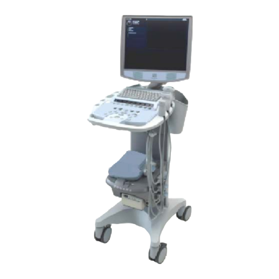
Page 30: Top-Level Product Overview
Figure 11: Label, Specialty Transducers - Serial/Part No. Figure 12: Label, AC Power Battery Adapter Figure 13: Label, AC Power Adapter Power Supply TOP-LEVEL PRODUCT OVERVIEW 4.1 Major Assembly Identification Page 30 of 244 Q00180 Rev B "Note: Copies are uncontrolled documents - For revision verification see the Master Documentation List"... -
Page 31: Transducers
SmartCart SP Scan Module Scan Engine Figure 14: Major Assembly Illustrations Z.ONEUltra 4.2 Transducers Linear Curved Phased Endo-Cavity Figure 15: Transducer Illustrations Page 31 of 244 Q00180 Rev B "Note: Copies are uncontrolled documents - For revision verification see the Master Documentation List"... -
Page 32: Accessory Components
4.3 Accessory Components USB Memory Stick Lithium-Ion Battery Pack 2-Pedal Footswitch AC Power Adapter Battery Charger, 2-Bay Page 32 of 244 Q00180 Rev B "Note: Copies are uncontrolled documents - For revision verification see the Master Documentation List"... -
Page 33: Smartcart Sp Major Assemblies (Shown With Mtp Multi- Probe Option)
4.4 SmartCart SP Major Assemblies (shown with MTP Multi- probe Option) Page 33 of 244 Q00180 Rev B "Note: Copies are uncontrolled documents - For revision verification see the Master Documentation List"... -
Page 34: Smartcart Sp User Interface Controls (Overview)
SmartCart SP User Interface Controls (Overview) Figure 16: SmartCart SP User Interface Controls (Overview) Page 34 of 244 Q00180 Rev B "Note: Copies are uncontrolled documents - For revision verification see the Master Documentation List"... -
Page 35: Sp Cart User Interface Controls (Detailed)
SP Cart User Interface Controls (Detailed) Figure 17: SP Cart User Interface Layout Page 35 of 244 Q00180 Rev B "Note: Copies are uncontrolled documents - For revision verification see the Master Documentation List"... - Page 36 4.6.1 SP Cart User Interface Functions Number System Control Description SETUP Used to bring up the system setup configuration menu. F1 –F2 Function keys, user configurable in System Setup menu EXAM TYPE Brings up selection of exam types to the OLED display windows. Transducer (MTP) Used to bring the available transducers to the OLED display windows, for selection of a desired transducer from the 3-Port...
- Page 37 Doppler (Pulsed Wave), toggle activates/de-activates Color (Doppler) Mode, toggle activates/de-activates B- Mode/2-D (Tissue mode) SELECT Activates currently highlighted selection in the on-screen menu. CALC Brings up the Calculations menu page. MEASURE Multi function key: 1) Brings up dynamic caliper (live) or Calc menu (frozen) 2) Toggles on/off the Auto-Dop Trace function, in PW Doppler mode OPTIMIZE...
- Page 38 “SET” Used to toggle the function of active items on display (equivalent to a “mouse click”) FREEZE Halts or re-starts active imaging on the display Trackball Used for positioning the cursor, defining size/position of ROI in color mode, positioning measurement tools, reviewing cine-loop images and navigating form/tables/worksheets/reports DEPTH Adjusts (Up/Down) the imaging depth of the display...
-
Page 39: Smartcart Sp Keyboard Controls (Detailed)
4.7 SmartCart SP Keyboard Controls (Detailed) Figure 18: SmartCart SP Keyboard Layout Page 39 of 244 Q00180 Rev B "Note: Copies are uncontrolled documents - For revision verification see the Master Documentation List"... - Page 40 KEYBOARD: SPECIAL FUNCTION CONTROLS System Control Description This is a toggle key. The first press will display the Patient Information page. NEW PATIENT The second press will return to the imaging display. If there is an exam in progress, pressing this key will display the in-progress CURRENT EXAM exam's images, most recently stored image displayed first.
- Page 41 Pressing Del Text will remove all text annotations and arrow graphics DEL WORD | DEL TEXT displayed. Pressing Shift+Del Word will delete the most recently entered text annotation, whether it be free text, POT, or List entry. Pressing Home will move the text annotation cursor to its default home position.
-
Page 42: Scan Engine User Interface Controls (Detailed)
Scan Engine User Interface Controls (Detailed) Figure 19: Scan Engine User Interface Layout (Detailed) 4.8.1 Scan Engine User Interface Functions Number System Control Description GAIN Controls the overall gain for B-Mode and Color Doppler Turns on the virtual DGC graphic Page 42 of 244 Q00180 Rev B "Note: Copies are uncontrolled documents - For revision verification see the Master Documentation List"... - Page 43 DEPTH Adjusts the imaging depth shown on the display 4, 16 FREEZE Halts or re-starts active imaging 5, 17 STORE Stores current image to the internal archive storage and sends images to device(s) previously specified in System Setup menu (DICOM printer, DICOM store, local Printer). When USB digital printer is selected, key press initiates sending a printed image to the B/W (or Color) printer PRINT...
- Page 44 F1, F2 Function keys, user configurable in System Setup menu OPTIMIZE Dual function: “ZST” Sound Speed Correction and/or “AutoOpt” (DGC) Advances through four (4) on-screen main menus (Imaging, Presets, Patient Info, Tools) 15, 16 see item 4 and 5 above SELECT Activates the currently highlighted selection in the on-screen menu.
-
Page 45: Smartcart Sp Rear I/O Panel: Layout & Functional Definitions
SmartCart SP Rear I/O Panel: Layout & Functional Definitions Figure 20: SmartCart SP Rear I/O Panel 4.9.1 Functions: I/O Connectors Function Direction DVI Digital Video (Using HDMI connector) Output USB Ports (4) Input/Output Ethernet 10/100BaseT - (Network) Input/Output 4.10 Scanner Rear I/O Ports: Layout & Functional Definitions Figure 21: Scanner Rear I/O Connections 4.10.1 Functions: I/O Port Connectors Jack #... -
Page 46: Aved: Audio-Video Extension Device - I/O Panel: (Option)
DVI Video - – [HDMI connector] Output +12VDC Input - (Zonare AC Power Adapter only!) Input 4.11 AVED: Audio-Video Extension Device - I/O Panel: (Option) Figure 22: AVED Option - I/O Panel (SmartCart SP) 4.11.1 Functions: I/O Connectors Function Direction... -
Page 47: System Uncrating & Installation Procedures
Shipping containers should be inspected for damages, and the “Tip-n-Tell” indicator for signs of mishandling during shipment. If any problems are found, immediately notify the shipping carrier. All installation and set-up of equipment should be done following official ZONARE product installation procedures. -
Page 48: Figure 22: Main Shipping Container Removal
Figure 23: Main shipping container removal 9. Remove the clear packing tape that is used to secure the foldable wooden loading ramp in its upward-facing shipping position. Lower the ramp on its hinges. Figure 24: Loading ramp lowering 10. Remove the clear packing tape that secures the front support to the base during shipping. Grasp the removable front support section of the wooden shipping base (at the bottom-front of the system), pull it directly outwards away from the Z.ONEULTRA SP, and set aside. -
Page 49: Mechanical Verification
Figure 26: Removing protective storage bag 12. Pull up to the top position on the brake pedal (at the front of the Z.ONEULTRA SP), to release locking of the SmartCart SP’s wheels. Figure 27: Brake release of wheels 13. Rotate the wheels from their 90 degree angled storage position, to be inline with the loading ramp and enable rolling the system out of crate. -
Page 50: System Installation
1. Check to ensure all peripherals, software level, and serial numbers correspond with sales order. Make note of any missing items or discrepancies, and immediately report to ZONARE. 2. Check the two AC power rating labels, located by the system power receptacle and inside the rear cover by the AC outlet box, to verify power rating matches AC power level present at installation site. -
Page 51: Figure 27: Battery Pack Installation
Figure 28: Battery Pack Installation 5.6.3 Docking Scanner onto SmartCart SP STEPS: 1. Place the Scan Engine (or Scan Module) in the molded area on the docking plate, so that it will align itself in the cradle. 2. Gently pull the unit towards you until you hear a clicking sound from the release lever securing the system into place. - Page 52 The SmartCart SP has the ability to be powered by AC or battery (IF the Z-PAK NOTE: battery pack “Option” is ordered). When the SmartCart SP is fully charged the battery should allow for normal system operation for more than 1 hour. When the scan engine is docked into the SmartCart SP, its internal battery is subject to being charged.
- Page 53 4. Using the underside of your finger, gently press-and-release (do not “HOLD”) the green- colored (rubber membrane) Power On/Off Switch at the back/left corner of the scan engine, to initiate the start of a power OFF sequence. Power On/Off Swtich The system will NOT immediately power down, as the Scan Engine will perform a properly NOTE: ordered shutdown sequence (taking approximately 10 seconds).
-
Page 54: Figure 29: Ac Power Adapter
However to allow for extended standalone operation of the Scan Engine, an AC Power Pack is available from Zonare as an alternate power source. The output connector of the AC Power Pack is plugged into the DC power port on the rear of the Advanced Hardware Scan Engine. - Page 55 There are no User or Field Service repairable components within the 2-Bay Battery Charger. Any defective units should be returned to the Zonare factory for repair/replacement. The Lithium-Ion battery packs, used to power the Scan Engine during standalone (undocked) use, have expected charge retention of approximately 1 hour (during full-use of the Scan Engine).
-
Page 56: Figure 30: 2-Bay Battery Charger
Figure 31: 2-Bay Battery Charger 5.6.7.1 “Recalibrating” Battery Packs Recommended Intervals: The Z.ONEULTRA SP battery pack contains Lithium-Ion battery cells as well as an electronic “fuel” gauge that keeps track of the charge and discharge cycles of the battery cells. During frequent charge/discharge cycles, it is possible for this fuel gauge to loose its synchronization to the actual charge remaining in the battery. - Page 57 11. During the “Recalibrate” process, the left status LED flashes ORANGE. Once the “Recalibrate” process is completed, this same LED will intermittently flash between ORANGE and GREEN. NOTE: - The “Recalibrate” process may require 14 hours to fully complete - The battery pack should NOT be removed prior to completion of the “Recalibrate” process, as the battery will be at an unknown level of charge 5.6.7.2 Charging Scan Engine Battery Packs...
-
Page 58: Transporting - Shipping The Scanner
5.7 Transporting - Shipping the Scanner STEPS: 1. If a transducer is attached to Scaner, disconnect it and store in an appropriately safe/protected manner 2. Ensure that the system is powered off 3. Undock the Scanner from the SmartCart SP 4. -
Page 59: Basic System Configuration
BASIC SYSTEM CONFIGURATION 6.1 Basic System Configuration Procedures • Entering “INSTITUTION” (Hospital) Name 1. Using the MENU button , bring up the menu and select Tools menu. TOOLS Menu 2. Using the Menu Control, arrow down to backlight SYSTEM SETUP selection, and press the SELECT button to bring up this menu. - Page 60 DISPLAY Sub-Menu INSTITUTION Sub-Menu 4. Using the alpha-numeric keyboard, enter Institution name (Note: Field is limited to 20 character positions) • Configuring “AUDIO/VIDEO” Setup • Within the Display selection, use the Menu Control to backlight Audio/Video selection, press Select button to bring up this menu. DISPLAY Sub-Menu AUDIO/VIDEO...
- Page 61 • Select the desired A/V setup parameters from the menu. This is done by using the trackball to move the arrow pointer (in conjunction with the SET key), or using the TAB key on the alpha-numeric keyboard to advance to each successive field, and the ENTER key to make selections.
- Page 62 • Entering “TIME/REGION” Information 1. Within the Display selection, use the Menu Control to backlight Time/Region selection, press Select button to bring up this menu. DISPLAY Sub-Menu TIME (DATE) Sub-Menu 2. Using the alpha-numeric keyboard, enter in the current date/time information. The TAB key on the alpha-numeric keyboard is used for advancing to each successive field.
- Page 63 • Entering “TRACKBALL” Configuration 1. Within the Display selection, use the Menu Control to backlight Trackball selection, press Select button to bring up this menu. DISPLAY Sub-Menu TRACKBALL Sub-Menu Cine Trackball Configuration: (Applicable to SmartCart systems ONLY) This menu allows for configuring the behavior of the trackball to users preferences, independently for a variety of Cine modes.
- Page 64 Cine Scroll Sensitivity • 2D Cine Trackball: (B-Mode or B-Mode/Color modes) Description: Controls the number of frames that are advanced in response to each swept trackball movement by the User. • Strip Cine Trackball: (M-Mode or Spectral Doppler modes) Description: Controls the rate at which the time axis sweep is advanced in response to each sweep of trackball movement by the User.
- Page 65 3. For each Transducer type in the pull-down menu, configure the power-up default application type and preset type that are desired. 4. Select the desired default Doppler settings. 5. Select the desired default Auto-Opt/ZST settings 6. Select the desired “DUAL” mode preset behavior setting 7.
-
Page 66: Archive Menu Functions
ARCHIVE MENU FUNCTIONS 7.1 “Media” & “Store/Print” Button Configuration 1. Using the TAB button advance the menu screen to select TOOLS 2. Using the Menu Control, arrow down to backlight the Archive selection, and press the SELECT button to bring up this menu. SYSTEM SETUP Sub-Menu ARCHIVE... - Page 67 • “MEDIA” Configuration 1. Within the ARCHIVE selection, use the Menu Control to backlight Media selection, press Select button to bring up this menu. ARCHIVE Sub-Menu STORAGE MEDIA Sub-Menu 2. Make any changes desired to the settings for still and clip image compression, and defined modality.
- Page 68 • “STORE/PRINT” Button Configuration 1. Within the ARCHIVE menu, use the Menu Control to backlight Store/Print selection, press Select button to bring up this menu. ARCHIVE Sub-Menu IMAGE STORE/PRINT BUTTONS Sub-Menu 2. Based upon what functions are desired to occur when the PRINT and STORE buttons on the Z.ONE are pressed, configure the settings in this menu.
-
Page 69: Exam Management" Menu
• Exam Completed: Images are buffered during each STORE key depression, and later placed as a group into the DICOM Queue for network/print transfer. The process for beginning the transfer of the images is automatically started when the Operator ends the current exam. 7. - Page 70 EXAM MGMT Sub-Menu 3. Configure the “Exams Restarted Using” selection to reflect the desired grouping of images upon restarting of a previous exam on the Customer’s system. • Prior Series: Appends new images onto the series of images previously captured. IMPORTANT “Prior Series”...
- Page 71 • Rebuild Patient Exam Database - Content: This option allows for specifying the granularity of the exam database rebuild process that is initiated with the “REBUILD” menu selection below. NOTE: The exam database content granularity selections (described below) does not have any effect (is not applicable) for rebuilds where the targeted device (via the pull- down selection) is an “External”...
- Page 72 Some Transducer file To prevent Users from accidentally performing this operation a “Service Password” prompt will appear prior to this “FORMAT” operation activating. Contact Zonare Technical Support in order to obtain the service password and assistance on this operation. Due to the erasing of some transducer files, reloading of system software will be required after performing this “FORMAT”...
-
Page 73: Serial Port" Setup - (Export Calc Report Data)
will completely reformat the media; erasing all contents. Due to the operation being a complete” FORMAT” where no individual files are accessed, it is completed very quickly. Select the desire media device using the provided pull-down menu. 7.3 “Serial Port” Setup - (Export Calc Report Data) The SERIAL PORT configuration menu allows for configuring the system to be able to “EXPORT”... - Page 74 6. Using the page TAB button to advance menu screen to select TOOLS menu; then select SYSTEM SETUP, then select ARCHIVE. SYSTEM SETUP Menu ARCHIVE Menu 7. Using the Menu Control, arrow down to backlight SERIAL PORT selection, and press the SELECT button to bring up this menu.
- Page 75 9. If desired for OB report data to be exported in sync with DICOM image transfers to the PACS system over the network, check the box for “Link Serial Connect to Ethernet Connect”. 10. Using the Menu Control, arrow down to backlight Apply selection in the main menu, and press the SELECT button...
-
Page 76: Dicom Configuration
Prior to installation of the Z.ONEULTRA SP at any medical facility utilizing a DICOM network environment, a “Pre-Install Survey Form” (ZONARE P/N: F00044) should have been completed. This form is used for obtaining, in advance, detailed networking and DICOM configuration values (IP addresses, AE Titles, etc.) from the IT/PACS System Administrator at the facility. -
Page 77: Dicom" Configuration Parameter Definitions
8.2 “DICOM” Configuration Parameter Definitions: The table below provides some guidance regarding the type of information required for the DICOM configuration of the various menus (“General”, “Printers”, Network Store”, “MPPS” and “Worklist”) on the Z.ONEULTRA SP. DICOM Configuration Parameters: Definition: Z.ONEULTRA SP AE Title The official “name”... - Page 78 DICOM Configuration Parameters: Definition: Log Level Defines the level of detail information that will be displayed in the DICOM Queue. Maximum entries cached Set according to department requirements. A higher number provides access to more scheduled exams, but increases the time required to search for the exam of Enter a number between 0 and 999 interest.
- Page 79 DICOM target devices. Scheduled Station AE Title Identity (Application Entity Title) assigned to the Zonare ultrasound system, for use in filtering patient exam scheduling data provided by the Worklist server. Value to be provided by PACs Admin, to meet department requirements.
-
Page 80: Z.oneultra Sp Pre-Install Survey Form (Sample Only)
General System / DICOM Setup Parameters Level Parameter Name User Site Value/Setting Default / Special Info User option Application (AE) Title – (Zonare System) ZONARE User option Station Name – (Zonare System) ZONARE User option TCP Timeout (sec.) User option Queue Timeout (sec.) - Page 81 User option Color Mode Color Grayscale Color User option Number of Copies User option Print Priority High User option Image Display Format Selections: (2x2, 1x1, 1x2, 2x1, 2x3, 3x2, 3x3, 3x4, 3x5, 4x3, 4x4, 4x5, 4x6, 5x4, 5x5, 5x6, 5x7) User option Medium Type Medium...
- Page 82 IQ Scan/Raw Data unchecked SR Document unchecked unchecked SR Private Data Key Image Note/Key Object Selection unchecked Document User option Release Association After storing each image in the exam After storing each image After storing the entire exam MPPS (Modality Performed Procedure Step - DICOM) Setup Parameters (if applicable) Level Parameter Name User Site Value/Setting...
- Page 83 Media – Storage Setup Parameters Level Parameter Name User Site Value/Setting Default / Special Info User option General: Modality Selections – Circle one if desired: (AU, BI, CD, CR, CT, DD, DG, DX, ECG, EPS, ES, FID, GM, HC, HD, IO, IVUA, KO, LS, MG, MR, NM, OP, OT, PR, PT, PX, REG, RF, RG, RTDOSE, RTIMAGE, RTPLAN, RTRECORD, RWV, SM, SMR, SR, ST, TG,...
-
Page 84: Dicom" Configuration Procedure - Menus
8.4 “DICOM” Configuration Procedure - Menus Refer to the “Survey Form” (on the previous pages), for detailed information of all the NOTE: values that are offered in the Z.ONEULTRA SP menus, for selection within the various fields, in each of the following configuration screens. •... - Page 85 Using the Menu Control, arrow down to backlight SYSTEM SETUP selection, and press the SELECT button to bring up the main menu, then select the ARCHIVE option, followed by the LOCATION option. SYSTEM SETUP Sub-Menu ARCHIVE Sub-Menu Within the Location selection, use the Menu Control to backlight selection, and Manage press the SELECT button...
- Page 86 CREATE Sub-Menu Enter in the desired user-defined name to be used for the new “Location” To save the new Location, select APPLY from the main menu, and press the SET key Open each of the configuration pages (Network, DICOM General, etc) for parameters that are savable under the Location manager, and enter in the desired settings.
- Page 87 SYSTEM SETUP Sub-Menu DICOM Sub-Menu Within the DICOM selection, use the Menu Control to backlight selection, and GENERAL press the SELECT button to bring up this menu. DICOM Sub-Menu DICOM GENERAL Sub-Menu Using the alpha-numeric keyboard, enter in the required DICOM configuration values/settings in the appropriate fields, as specified in the information previously provided in the “Pre-Installation Site Survey Form”, by the medical facility’s IT System Administrator.
- Page 88 • DICOM “PRINTERS” Configuration 1. Within the DICOM selection, use the Menu Control to backlight selection, and PRINTERS press the SELECT button to bring up the DICOM Printer Administration menu. DICOM Sub-Menu PRINTER Administration Sub-Menu 2. To create an entry for a new printer to be added to the DICOM connectivity for the Z.ONE, use the Menu Control to backlight from the main menu, and press the SELECT button to bring up the...
- Page 89 3. Using the alpha-numeric keyboard, enter in the DICOM configuration values/setting in the appropriate fields, as specified in the information previously provided in the “Pre- Installation Site Survey Form”, by the medical facility’s IT System Administrator. 4. To save the new settings, select APPLY from the main menu, and press the SET key save new settings.
- Page 90 3. Using the alpha-numeric keyboard, enter in the DICOM configuration values/setting in the appropriate fields, as specified in the information previously provided in the “Pre- Installation Site Survey Form”, by the medical facility’s IT System Administrator. 4. To save the new settings, select APPLY from the main menu, and press the SET key save new settings.
- Page 91 • DICOM” WORKLIST” Configuration 1. Within the DICOM selection, use the Menu Control to backlight Worklist selection, press Select button to bring up this menu. DICOM Sub-Menu DICOM WORKLIST CONFIG Sub-Menu 2. Using the alpha-numeric keyboard, enter in the DICOM worklist values/setting in the appropriate fields, as specified in the information previously provided in the “Pre- Installation Site Survey Form”, by the medical facility’s IT System Administrator.
-
Page 92: Network" Setup
8.5 “Network” Setup The “NETWORK” configuration menu allows for configuring the TCP/IP networking parameters that will be assigned to define the identity of the Z-ONE on the hospital’s network. 1. Using the page MENU button to bring up the menu, then select the TOOLS menu, then select SYSTEM SETUP. - Page 93 The Quatech AirborneDirect Wireless Ethernet Bridge supports WiFi 802.11b/g wireless standards and connects to the ZONARE system through a 10 Base-T network interface. This device supports WEP (64/128 bit) and WPA encryption standards, and LEAP for network authentication (LEAP required the Quatech device to be configured with a static 128 bit key;...
- Page 94 Quatech AirborneDirect device that is connected to the Ethernet port on the ZONARE system, it will require 30 to 60 seconds to detect and then associate with the user's wireless network. Once a wireless network connection is established, the ZONARE system will reflect the connection state by showing the network ICON on screen, in an uncrossed state.
-
Page 95: Advanced System Setup Configuration
ADVANCED SYSTEM SETUP CONFIGURATION 9.1 “Security” Setup Menus WARNING If the security password is lost or forgotten, there is NO master password available to recover system access. To restore use of the it will be necessary to perform a complete re- Z.ONEULTRA SP installation of system software. - Page 96 3. Select the desired level of security control, by clicking on the bullet to the left of the desired offering in the menu. ACCESS CONTROL Sub-Menu 4. Under the Logon Password field, enter in the desired security access password. (NOTE: You will need to enter it in a second time in the “CONFIRM”...
-
Page 97: Power Save" Setup Menu
9.2 “Power Save” Setup Menu • Configuring “Power Save” Configuration 1. Within the System Setup screen, use the Menu Control to backlight Power Save selection, press Select button to bring up this menu. SYSTEM SETUP Sub-Menu POWER SAVE Sub-Menu The three different categories of power operation mode configurations in this menu are: Title Definition Scan Engine Battery... - Page 98 2. For each of the power configurations, select the desired power saving option, and enter the desired time interval, from the menu. Unchecking the “Enabled” box, for either option, disables that time-out function NOTE: 3. Place the arrow cursor over the APPLY soft-button displayed in this menu, and press the SET key to save new settings.
-
Page 99: General Procedures
10 GENERAL PROCEDURES 10.1 Installing USB Memory Stick, into the Scan Engine STEPS: 1. Open the access cover door, at the rear of the Scan Engine 2. Hold the USB Memory stick properly aligned with the USB port connector on the Scan Engine. -
Page 100: Functional Descriptions
11 FUNCTIONAL DESCRIPTIONS 11.1 Overall System 11.1.1 Features Overview SYSTEM OVERALL: 64-hardware - 128/192-synthetic channel system • Supports B-Mode, M-Mode, Color, Power Doppler, PW, CW modes • SMARTCART SP: 19” full-screen, 1280 x 1024 resolution, Display • Full-sized alpha-numeric user keyboard •... - Page 101 • Internal CompactFlash Storage (Primary image archive) • USB 2.0 Full-speed port • +12V/6A DC power input port • DVI (HDMI connector) digital video output port 11.1.2 Electronics Overview (Scanner) • Digitally programmable transmit control • Pulser - Transmitter • Analog front end •...
-
Page 102: Smartcart Sp
• SmartCart SP Z-PAK battery fuel gauge • PIC Power Supply Controller logic • External system status LEDs (5) 3. Scanner Deck (Pallet) Assy (w/MTP) .......Zonare P/N: 85118-00 System Functions: • Mechanical docking and locking mechanisms • Optical sensors for scan engine docking detection •... - Page 103 • Discrete functional controls 5. OLED Display Board ............Zonare P/N: 85095-00 System Functions: • OLED soft-function displays 6. MTP Bolster Plate – Service FRU........Zonare P/N: 85123-00 System Functions: • Multi Transducer Port switching relays 11.2.2 Electro and Mechanical Assemblies 1. Brake Mechanism - Wheel Description: The SmartCart SP has 3 different swivel/lock positions of the foot pedal on the front wheels.
-
Page 104: Figure 32: Smart Cart Sp: Brake Mechanism
• In the fully down position of the foot pedal the brake mechanism will lock the front wheels from rotation. This prevents undesired movement of the SmartCart SP during system operation. In addition to locking the brake, the front wheels may be rotated to a 90-degree angle, prior to locking foot pedal down, to provide additional system stability during shipping. -
Page 105: Power & Signal Distribution Diagrams
12 POWER & SIGNAL DISTRIBUTION DIAGRAMS BEGINS ON NEXT PAGE Q00180 Rev B Page 105 of 244 "Note: Copies are uncontrolled documents - For revision verification see the Master Documentation List"... -
Page 106: Smartcart Sp Power Module Block Diagram (Basic)
12.1 SmartCart SP Power Module Block Diagram (Basic) Figure 35: SmartCart SP: Power Module Block Diagram (Basic) Q00180 Rev B Page 106 of 244 "Note: Copies are uncontrolled documents - For revision verification see the Master Documentation List"... -
Page 107: Smartcart Sp Power Module Block Diagram (Detailed)
12.2 SmartCart SP Power Module Block Diagram (Detailed) Figure 36: SmartCart SP: Power Module Block Diagram (Detailed) Q00180 Rev B Page 107 of 244 "Note: Copies are uncontrolled documents - For revision verification see the Master Documentation List"... -
Page 108: Smartcart Sp Main Board Cable Connection Diagram (Original Dvd Configuration)
12.3 SmartCart SP Main Board Cable Connection Diagram (Original DVD Configuration) Figure 37: SmartCart: Main Board Cable Connection Diagrams (Original DVD Configuration) Q00180 Rev B Page 108 of 244 "Note: Copies are uncontrolled documents - For revision verification see the Master Documentation List"... -
Page 109: Smartcart Main Board Cable Connection Diagram (Ide/Sata Adapter Dvd Configuration)
12.4 SmartCart Main Board Cable Connection Diagram (IDE/SATA Adapter DVD Configuration) Figure 38: SmartCart: Main Board Cable Connection Diagrams (IDE/SATA Adapter DVD Configuration) Q00180 Rev B Page 109 of 244 "Note: Copies are uncontrolled documents - For revision verification see the Master Documentation List"... -
Page 110: Functional Block Diagrams
13 FUNCTIONAL BLOCK DIAGRAMS BEGINS ON NEXT PAGE Q00180 Rev B Page 110 of 244 "Note: Copies are uncontrolled documents - For revision verification see the Master Documentation List"... -
Page 111: Smartcart Sp Overall System Block Diagram
SmartCart SP 13.1 Overall System Block Diagram Figure 39: Overall System Block Diagram - Z.ONEUltra Q00180 Rev B Page 111 of 244 "Note: Copies are uncontrolled documents - For revision verification see the Master Documentation List"... -
Page 112: Assembly Diagrams
14 ASSEMBLY DIAGRAMS 14.1 SmartCart SP: Power Module Functional Identification Figure 40: SmartCart SP: Power Module Functions Diagram Q00180 Rev B Page 112 of 244 "Note: Copies are uncontrolled documents - For revision verification see the Master Documentation List"... -
Page 113: Peripherals & Accessories
15 PERIPHERALS & ACCESSORIES 15.1 DVD/CD Burner - (Internal)" 15.1.1 General Info: The Z.ONEULTRA SP (SmartCart SP) includes an internal DVD/CD burner that is used for exporting of ultrasound images. The port for accessing the DVD/CD drive for insertion/removal of media, is located at the front of the SmartCart SP, just below the scan engine docking area. -
Page 114: Aved - Audio Video Extension Device Box - (Option)
(primarily analog) to support connection to additional peripheral devices. The connection of the AVED box and the Zonare Z.ONEULTRA SP is made through a single HDMI- >HDMI cable. The AVED box receives its operating power (+5V), controls, and digital video and audio information via this single cable that attaches directly between the external HDMI port on the rear of the SmartCart SP, and the HDMI Input port on the AVED box (as shown below). - Page 115 Only the HDMI->HDMI cable provided by Zonare should be used, as cables of additional length may result in loss of operation of the AVED; due to voltage drop induced by the added impedance. SPECIAL NOTE The S-Video and Composite video outputs (output #6 and #9 in the I/O Panel Diagram on the following page) on the AVED box only support video formats of a maximum resolution of 800 x 600.
-
Page 116: Figure 39: Aved: Audio Video Extension Device I/O Panel Diagram
The AVED box converts the digital video and audio information from the SmartCart SP into a variety of analog video formats, and analog and digital audio outputs. The I/O ports, and their functions on the AVED, are listed below. The VCR CTL remote trigger output is generated by pressing of the “RECORD” key on the User Interface of the SmartCart SP. - Page 117 Composite Video (Analog) - (800x600 mode only!) Output Q00180 Rev B Page 117 of 244 "Note: Copies are uncontrolled documents - For revision verification see the Master Documentation List"...
- Page 118 15.2.3 AVED Activity/Status LED – Codes: There is a single LED on the AVED box that is used to display the current operating status of the I/O activities. The status is indicated via a series of codes of flashing sequences. Below is a listing of the activity code states: 3 short “On”...
- Page 119 Using the TAB button advance the menu screen to select TOOLS Using the Menu Control, arrow down to backlight the System Setup selection, and press the SELECT button to bring up the main menu. SYSTEM SETUP Sub-Menu Using the Menu Control, arrow down to backlight the Keys selection, and press the SELECT button to bring up the configuration menu.
-
Page 120: Sony Up-D897 Usb Digital Printer
To save the Function Key assignment, select APPLY from the main menu, and press the SET to save new setting. 15.3 SONY UP-D897 USB Digital Printer 15.3.1 Procedure Notes: The intent of this procedure is to provide instructions, for use in the field, for the setup of the SONY UP-D897 Digital (USB 2.0) B/W Printer, on a SmartCart SP or miniCart. - Page 121 STEPS: 1. Following the steps below, using the front panel display menu and Jog Dial control, configure the initial user settings on the UP-D897 printer to match those shown in Figure 1, on the following page. “LOCK”ALERT The MENU operations on the Sony UP-D897MD printer have a special hidden “LOCK” function that if active will completely disable making any changes to the menu settings on the printer.
-
Page 122: Figure 40: Menu Settings (Up-D897)
NOTE: The setup menu will exit, and automatically return to the normal “Ready” printer state, when no new user actions are made on the jog dial for approximately 20 seconds. Setting Name Description Zonare Recommended Value BEEP Audible Tone CLEAN Initiate head cleaning operation n/a –... - Page 123 15.3.3 Printer Menu Configuration Process: STEPS: 1. Access the New Printer menu, using the path System Setup->Archive->DICOM->Printers->New 2. Using the pull-down menu, under the “TYPE” selection, select the USB printer. The menu will change to the limited setup page for a USB style printer (as shown below) 3.
-
Page 124: Figure 41: Operator Controls (Up-D897)
2. Under the “Network/USB Printer” function for the “Print” button, check the box to the left of the drop-down menu, enable this function 3. In the drop-down menu for this function, select the “SONY UP-D897” selection 4. Select “APPLY” from the main menu, to save the changed settings Operator Controls Figure 43: Operator Controls (UP-D897) Power ON/OFF Switch... - Page 125 JOG Dial (menu control) CONTRAST BRIGHTNESS RECEIVING (indicates active print data transfer) FEED (one-time push feeds paper, or holding during print cancels job) COPY (prints another copy of previously transferred image) OPEN (one-time push opens paper door, or holding during print cancels job) CUT (cuts paper after image is printed) 15.3.5 Print Verification: STEPS:...
-
Page 126: Sony Up-D23Md Color Printer
15.4 SONY UP-D23MD Color Printer 15.4.1 Installation Notes: SPECIAL NOTE The Sony UP-D23MD Color Printer is oversize and is therefore not a peripheral that can be “mounted” within the chassis of the . A separate external location Z.ONEULTRA SP (rolling cart, tabletop, etc) must be made available for storing of this printer. The system software on the Z.ONEULTRA SP system contains the necessary drivers to support operation and printing to the Sony UP-D23MD Color Printer. -
Page 127: Hp Laserjet Network (Report) Printer
5. Verify a printed image is produced on the UP-D23MD when the “Print” key on the SmartCart SP is depressed. NOTE: Refer to the SONY UP-D23MD Operators Manual, for detailed information on proper operation of this device. 15.5 HP LaserJet Network (REPORT) Printer 15.5.1 Procedure Notes: The intent of this procedure is to provide instructions, for use in the field, for setup and use of a Post Script-3, PS3 (or above) style, HP LaserJet Network Printer, for Report printing, on a Z.ONEULTRA... - Page 128 1. Connect the AC power cord to the printer, and the other end to an active AC Power outlet 2. Connect one end of the network crossover cable to the HP LaserJet printer, and the other end to the Ethernet (RJ-45) port on the Z.ONEULTRA SP. 3.
- Page 129 • Print/Export on End of Exam: (as desired by User) • Select “APPLY” in the menu, to save the settings NETWORK Installations Only: To meet regulatory requirements for user safety, Ethernet “Network” connectivity is the only method recommended for attaching the HP LaserJet printer to the Z.ONEULTRA SP. In this configuration a direct cable connection will be used between the printer and the Z.ONEULTRA SP (using a “crossover cable”).
- Page 130 Network Configuration Page 14. Using the arrow cursor and SET key, check the box for “USE SPECIFIED” 15. In the data entry box to the right of the “USE SPECIFIED” checkbox, enter in an IP Address that is one greater then the value of the HP LaserJet printer (i.e printer: 192.168.1.1, Z.ONEULTRA SP: 192.168.1.2) 16.
-
Page 131: 2- Pedal Footswitch
15.6 2- Pedal Footswitch 15.6.1 Information: An optional USB-style remote footswitch is available for use on the system, to enable the User to initiate several normal user operations, while their hands are previously occupied in the scanning of the patient. The two normal user interface buttons/functions that are assigned (not programmable) for optional footswitch control;... -
Page 132: Software Procedures
16 SOFTWARE PROCEDURES 16.1 Standard Software Installation/Upgrade Procedure CAUTION If performing software upgrades with the Scan Engine out of the Cart (un-docked) it is extremely important to ensure that the battery has a minimum of 50% charge capacity, PRIOR to beginning this software upgrade procedure. If the charge is too low, either replace the existing battery with a properly charged one, or temporarily dock the Scan Engine in the Cart, (with the Cart’s having AC power applied and the circuit breaker in the “On”... - Page 133 7. A final “Welcome to Install” screen should appear 8. Press the “SELECT” key again to begin the software installation process. 9. The in-process installing status screen should appear, with a bar graph indicating a dynamic percent completion status NOTE: The main application install process should complete in approximately 5 minutes. 10.
-
Page 134: Advanced" Software Installation Procedure
16.2 “Advanced” Software Installation Procedure SPECIAL INFO − In cases where the revision level of the software on the Z.ONEULTRA SP is being transitioned in a non-standard fashion, or has become corrupted and the system will not boot to perform a normal software installation process, the following advanced software installation steps should be used. - Page 135 16.2.2 Advanced Install Operations: SPECIAL NOTE: Pressing one of the following keys on the keyboard of the Scan Engine (or SmartCart SP if Scan Engine is “docked”), will bring up additional key functions into the on-screen menu (as shown above) Pressing the OPTIMIZE key will assign F1 to: “Clean SW Install”...
- Page 136 Installs software from USB Memory Stick, over-writing Optimize (erasing) existing User Presets and System (configuration) Clean SW Install Presets, with Zonare default values. NO formatting of the media is performed. The “C” and “D” partitions of the internal media of the Scan Optimize -> Measure...
-
Page 137: Scan Module: Standard Software Installation/Upgrade Procedure
16.3 SCAN MODULE: Standard Software Installation/Upgrade Procedure ATTENTION The Scan Module MUST be docked in the Cart in order to perform a Standard (user setting auto backed-up/restored). Any software install performed with the Scan Module undocked, will execute as a “Clean” install process (no user settings retained). - Page 138 NOTE: The main application install process should complete in approximately 5 minutes. 18. After file installation is completed, the system will run a brief install verification process. The following screen will appear during this verification 19. At the completion of a successful software installation/verification process, a dialogue box with the following message should appear on the LCD Display screen 20.
-
Page 139: Scan Module: "Clean" Software Install Procedure ("Docked")
16.4 SCAN MODULE: “Clean” Software Install Procedure (“Docked”) 1. Press the Power On/Off button to power the system on 2. Allow the system to complete a normal boot operation (less then 1 minute) 3. Insert the USB Memory Stick (containing system software installer files) into any one of the four USB ports at the rear of the SmartCart, pressing lightly to ensure it is seated in the connector 4. -
Page 140: Scan Module: "Clean" Software Install Procedure ("Undocked")
USB Memory Stick, PRIOR to performing this form of software installation on the Scan Module. 1. Attach a Zonare AC Power Adapter (option) to the DC power input port on the rear of the Scan Module, or have the Scan Module physically docked on Scanner Deck of SmartCart. - Page 141 5. The LED on the USB Memory Stick will begin flashing, to indicate the start of the software installation process. 6. The LED will intermittently continue to flash during the entire duration of the software installation • Total install time: Approx 4 minutes The Scan Module will automatically power off, to indicate the completion of the software installation.
-
Page 142: Ftp Site Access: Software/File Downloads From Zonare
16.6 FTP Site Access: Software/File Downloads from Zonare SPECIAL INFO − Zonare’s “TECH SUPPORT”FTP site area is provided to enable global access by Customers, Distributors, and Service personnel. − This tool is intended to allow direct access for downloading of file provided by Zonare Tech Support, (like downloads of new System Software). - Page 143 NOTE − EXTENDED “Serivce”key press will initiate an immediate manual capture of system “LOG” files. Normal Menu Path Method: 1. Using the “Tab” button and Menu Control on the Scan Engine (or SmartCart SP) user interface, advance to the “Tools” menu and then sequence through the following selection: Tools tab -->...
- Page 144 ZONARE • Checking for availability of software upgrades from remote ZONARE FTP site • Remote (over the internet) software upgrade of the Z.ONEULTRA SP from the ZONARE FTP site • Forcing a system REBOOT, to the BOOT-APP screen (for Scan Module “Clean SW Installs”)
- Page 145 The additional functions available beyond the main page of the User Diagnostic Panel, in these three sub-menus, are as defined below: • SETTINGS o FTP Access Setup – (IP Addressing) Software Upgrades Log File Transfer o Auto-Log File Reporting Configuration Q00180 Rev B Page 145 of 244 "Note: Copies are uncontrolled documents - For revision verification see the Master Documentation List"...
- Page 146 • MAINTENANCE o Firmware Upgrades – Z-PAK Maintenance – Scan Module SW Load (Service Reboot) • SERVICE o Service Password (Enable Proprietary Function Access) 16.7.3 PC Board Version Information 1. Using the trackball, position the arrow cursor over the DETAILS box 2.
- Page 147 FTP access. 1. On the Diagnostic page, in the “ZONARE SUPPORT” area on the screen, ensure that the following FTP remote access parameters are configured for the proper serial number of the Scan Engine in the Z.ONE.
- Page 148 16.7.5 MANUAL Log File Capture (Store) – Download to ZONARE 1. Using the trackball, position the arrow cursor over the Store Current Logs box 2. Press the “SET” button to initiate the creation of the LOG directory and the writing (“Capture”) of the log files to the internal CompactFlash storage media.
- Page 149 4. To download the log folder contents (which also contains the stored .BMP Image file) to the ZONARE Tech Support, enter the proper IP Address, User Name, and Password values in the entry boxes on the screen (values as provided by ZONARE Tech Support) NOTE: The Scan Engine must be docked in the SmartCart SP and the Z.ONEULTRA SP...
- Page 150 16.7.8 Remote Software Upgrade (download) from ZONARE site NOTES: PRIOR to beginning a remote software download/installation process, it is necessary to contact Zonare Technical Support, for assistance in setting up the necessary software files on the FTP site, for each remote software upgrade session.
-
Page 151: Cleaning And Disinfecting Procedures
17 CLEANING AND DISINFECTING PROCEDURES 17.1 SmartCart SP 17.1.1 Cleaning SmartCart SP LCD Display CAUTION • Take care not to damage or scratch the glass or LCD panel. • Do not apply pressure on the glass or LCD panel. • Do not apply or spray liquid directly to the glass, panel or cabinet as excess liquid may cause damage to internal electronics. -
Page 152: Scan Engine
External Case: CAUTION • Do NOT expose the external case to any of the following: − Cidex − Betadine − Alcohol (Isopropyl and Ethyl) − Ammonia based cleaners (Windex) − Aquasonic Gel 1. Power down the Z.ONEULTRA SP ultrasound system 2. -
Page 153: Transducers
: • Immersion Solutions Only disinfectants listed below are tested and approved for use on the ZONARE transducers specified above. No other products should be used, as damage to the transducer may result. • CIDEX •... - Page 154 There are two methods of cleaning and disinfection available for the Z.ONE transducers. Ultra • For external-use transducers (CLA and LA), ZONARE recommends performing the “wipe method” (described next) after each exam. In addition, ZONARE recommends performing the immersion method disinfection weekly.
-
Page 155: Figure 44: Transducer Immersion Limits
CAUTIONS During immersion disinfection, never immerse the transducers longer than the maximum specified time (as per the Operator Manual instructions) of 45 minutes. Damage may occur to the transducer housing and/or components if disinfection times exceed these recommended limits. Using a non-recommended cleaning or disinfectant solution, incorrect solution strength, or immersing the transducer deeper or longer than indicated can damage the transducer. - Page 156 7. Follow the instructions on the disinfectant label for the duration of transducer immersion; do NOT exceed the 1 hour maximum ZONARE-specified limit. 8. Following the instructions on the disinfectant label, thoroughly rinse all areas of the transducer below the immersion level.
-
Page 157: Maintenance - Calibration Procedures
18 MAINTENANCE – CALIBRATION PROCEDURES 18.1 Foreword Being a digital front-end imaging system, and non-mechanical device, the Z.ONEULTRA SP has a very limited number of routine maintenance and calibration procedures that will be required. The maintenance procedures currently described in this manual, are very basic in nature, and may therefore be performed by the Operator, as well as normal Service personnel. -
Page 158: Z-Pak "Recondition" Procedure - (Smartcartsp)
18.4 Z-PAK “RECONDITION” Procedure - (SmartCartSP) STEPS: 9. Ensure the AC circuit breaker, at the rear of the SmartCart, is in the On (“1” pressed IN) position. 10. Fully boot up the system and then press the “SERVICE” key (third key from top-right) on the SmartCart, to bring up the DIAGNOSTIC page. -
Page 159: Ui Lift (Gas Spring) Release Cable Adjustment - (Smartcart Sp)
18.5 UI Lift (Gas spring) Release Cable Adjustment - (SmartCart SP) 18.5.1 Gaining access to cable adjuster STEPS: 1. Ensure the Z.ONEULTRA SP is powered “OFF”. 1. Place AC circuit breaker, located at the rear of the SmartCart SP, in the “OFF” position. 2. -
Page 160: Touchscreen Calibration - (Scan Engine)
NOTE 2: If the cable is too tight (the lift is not staying locked in position when the release lever handle is fully released – aka “drifting”), rotate the adjuster barrel in the clockwise (opposite to what is shown in the illustration above) direction just far enough to resolve the “drifting”... - Page 161 2. In a single-firm contact motion, touch (and hold) the stylus to the center of the 1 target point until the Z.ONEULTRA SP detects this contact, and moves the calibration target point graphic to the next (2 ) calibration position. 3.
-
Page 162: Display Monitor Adjustment - User Settings
18.7 Display Monitor Adjustment – User Settings 18.7.1 SmartCart SP Display User Settings Adjustment There are no local adjustment knobs on the LCD Display used on the SmartCart SP. The display settings of the monitor are controlled remotely (via the DVI video cable connection), by an on- screen Audio/Video control menu on the system. - Page 163 Visually inspect the output of the LCD Display, to confirm the desired video levels are achieved. Repeat the above steps, if required Grayscale Test Pattern: 1. Using the “Tab” button and Menu Control on the user interface, advance to the “Tools” menu 2.
-
Page 164: System Troubleshooting
FRU’s (Field Replaceable Units). 19.2 Technical Support Contact Information • USA, Canada and Asia ZONARE Medical Systems Inc 420 N. Bernardo Avenue Mountain View, CA 94043 Toll-free live-phone support: ..... 1-877-913-9663 (5:00AM – 5:00PM, Pacific Standard Time) Tech Support FAX line ...... - Page 165 Tech Support Phone ......(+49) 9131-974 94-0 (8:00AM – 5:00PM) Tech Support e-mail ......info@zonare.de Corporate web site......www.zonare.com FTP site (Tech Support Window): − URL ..........ftp://12.40.200.87 • Enter the following User Name and Password information: User Name: (call Tech Support for current login information)
-
Page 166: Troubleshooting
Bent, broken, or missing pins on the transducer connector may cause poor image quality, including possible mirror image artifact. Be sure to check pins before connecting transducer to the ZONARE ultrasound system. If pins are bent, broken, or missing, do not use the transducer and call ZONARE Technical Support. - Page 167 SmartCart SP or the Scan Engine. 9. If either component fails to start up after these steps, contact ZONARE Tech Support. SmartCart SP – System Power-Up Sequence 1. Turn off system (circuit breaker off or unplug), remove Scanner from SmartCart SP...
- Page 168 NOTE: BootLoad mode results in inability for system to check for scanner docking present, and does not illuminate any of the five system status LEDs on the rear panel of the SmartCart Turn off the SmartCart SP with another push of the On/Off button 5.
- Page 169 • Temporarily connect the AC power cord of the peripheral to a local AC receptacle, and test for operation of the peripheral. • If the peripheral fails to power on after these steps, contact ZONARE Tech Support. Local printer fails to print...
- Page 170 USB port on the Main Board in the SmartCart SP. • Ensure the AC power cable is securely connected at the rear of the printer. • If the printer fails to print after these steps, contact ZONARE Tech Support. 19.3.5 Transducer Problems Transducer not recognized by system (no B-mode imaging) •...
- Page 171 1 hour for fully charging of the battery. If not, repeat previous dock/un-docking cycle sequence. 19.3.7 Imaging Problems No/poor B-mode image • Ensure that the brightness and/or contrast settings of the LCD display are set close to factory default levels on the SmartCart SP. Default settings are indicated by the asterisk (*) in the pop- up menu.
- Page 172 19.3.8 General Operation Problems Function (F1-F2) key(s) do not operate • Using the on-screen menu, follow the path: TOOLS | SYSTEM SETUP | FUNCTION KEYS) to access the menu for the user configuration of the assignments of the function keys. •...
-
Page 173: System Status Led & Error Code Definitions
19.4 System Status LED & Error Code Definitions 19.4.1 SmartCart SP 19.4.1.1 On-Screen “Dashboard” System Status ICONs If the SmartCart SP is equipped with the on-board battery option, two (2) battery icons NOTE: will displayed on the upper-lefthand corner of the LCD display of the SmartCart SP. If there are two battery icons, the icon on the LEFT represents the SmartCart SP main battery and the icon on the RIGHT represents the Scan Engine battery (if present). - Page 174 Scan Engine Image storage is occurring to the Scan Engine internal media Internal Media Scan Engine >20% of Scan Engine internal media storage capacity Internal Media remaining Scan Engine 5-20% of Scan Engine internal media storage capacity Internal Media remaining Scan Engine <5% of Scan Engine internal media storage capacity remaining Internal Media...
- Page 175 Scan Engine or Storage operation is actively in-process to removable storage Cart Removable media (USB) Media (USB) Scan Engine or >20% of capacity of removable storage media (USB) still Cart Removable remains Media (USB) Scan Engine or 5-20% of capacity of removable storage media (USB) still Cart Removable remains Media (USB)
- Page 176 Wireless Network Wireless signal strength: 21% – 40% Wireless Network Wireless Network Wireless signal strength: 41% – 60% Wireless Network Wireless Network Wireless signal strength: 61% – 80% Wireless Network Wireless Network Wireless signal strength: 81% –100% Wireless Network Q00180 Rev B Page 176 of 244 "Note: Copies are uncontrolled documents - For revision verification see the Master Documentation List"...
- Page 177 19.4.1.2 Rear I/O Panel – System Status Lamps The five (5) system status indicator lamps located on rear of the SmartCart SP (panel just above the main AC circuit breaker) can be used to assist in troubleshooting problems with the system. The definition of the each lamp is as shown in the table below: STATUS Definition...
- Page 178 19.4.2 Scan Engine ................. *Power-On Switch LED ............**Scan Engine Activity LED : (Solid): Scan Engine is currently powered On : (Off): Scan Engine is currently powered down ***Battery Charge Level ................75-100% charged ................50-75% charged ................... 25-50% charged ..................
- Page 179 **SCAN ENGINE ACTIVITY LED – ERROR CODES: The MPC (Controller) in the Scan Engine blinks this LED at a 1Hz. Rate, formulating an error code (prior to initiating a system shutdown) if any of the following hardware error conditions occurs: 3 Blinks: ........
- Page 180 19.4.3 System Error Message Codes Action On Error Code Subsystem Message for Error Log User Error Message Error "Thermal Sensor Error: Please shutdown 0xa0060402 ThermalControl Sensor Error system." STOP "System Overheat Warning: Finish exam 0xa0060403 System Overhead Warning and shutdown." CONTINUE "Battery Overheat Warning: finish exam 0xa0060405...
-
Page 181: Scan Engine Fan Operation
Action On Error Code Subsystem Message for Error Log User Error Message Error 0xe00a0414 HV's Crossed "Internal System Error has occurred" RESTART 0xe00a0415 High Voltage "Internal System Error has occurred" RESTART 0xe00d0000 Imaging Pipeline Fault Event Occured. "Internal System Error has occurred" RESTART 0xe0100401 Router... -
Page 182: Battery Performance - Charge Times - Reconditioning
19.7 Battery Performance – Charge Times - Reconditioning 19.7.1 Foreword: The following information is intended to provide an overview on the battery-driven system operation times and charging intervals for the Z-PAK battery pack in the SmartCart, and the removable battery pack used inside the Scan Engine. -
Page 183: Repair Procedures
........5.0 Hours (approx) 20 REPAIR PROCEDURES 20.1 Foreword The repair procedures described in this portion of the Service Manual should be performed ONLY by a ZONARE trained service personnel (Service Engineer, Bio-Med, etc.). 20.2 Recommended Tools Tool Description Size Qty. -
Page 184: Hardware Service/Replacement Procedures (Smartcart Sp)
Socket Wrench Set, (10mm, 13mm) Multi-sizes 1 set SmartCart SP gas spring (13mm) Combination Wrench Set (Metric) 19mm miscellaneous Allen Wrench Set (Metric) 2.5mm, 5mm SmartCart SP gas spring Flashlight, Mini-Mag 6” size Illuminating tight access areas Magnetic pick-up tool Telescoping Retrieval of hardware 20.3 Hardware Service/Replacement Procedures (SmartCart SP) - Page 185 7. While supporting the display/display arm from swinging to the side, on a soft surface (carpet, etc.) tilt the Cart forward, until it is horizontal, resting on the two front push handles for support CAUTION The Cart may be heavy and care should be taken while tilting forward, use two people if necessary to avoid injury.
- Page 186 13. Once installation is complete, Tilt the Cart back up onto its wheels, and release the brake mechanism. 14. Verify smooth operation and pivoting of the Cart through all movements. 15. Verify that the brake functions correctly and that each caster locks and the brake functions when it is set.
- Page 187 Cable retention screw 5. Remove the (6) Phillips-head screws that are retaining the plastic display hinge back cover, and remove back cover and insert. 6. Remove the aluminum tape securing the video cable to the display. 7. Using the long straight slot screwdriver – loosen the display cable retention screw. 8.
- Page 188 9. Tilt the top of the display towards the rear of the cart to support the LCD Display while removing the last screw. 10. Taking weight off the display, slide it off the threaded studs on the metal hinge assy. 11.
- Page 189 1. Reconnect the main AC power cord from the rear of the SmartCart SP or plug into the wall source. 2. Place AC circuit breaker, located at the rear of the SmartCart SP, in the “ ” (On) position. 3. Ensure the scan engine is docked in the SmartCart SP. LED 1 will blink quickly and LED 5 will remain on.
- Page 190 • #2 Phillips Screwdriver – Stubby • #1 Phillips Screwdriver • 9/32” Nut Driver or wrench • 7/64” Allen Wrench • Wire Cutters Procedure Opening Chassis Cosmetics: STEPS: 1. Ensure the Z.ONEULTRA SP is powered “OFF”. 2. Place AC circuit breaker, located at the rear of the SmartCart SP, in the “OFF” position. 3.
- Page 191 6. Slide the outer cosmetic chassis sleeve down and grab the inner sleeve front panel along with the outer sleeve at the same time from above. 7. Lift both the Inner and Outer sleeve to gain access to the Scanner Deck retention screws. There is one spring clip in the center which holds the inner panel down.
- Page 192 Deck Screws Looking up from wheels to front handle from below. 4. Partially lift the Scanner Deck off the Electronics Enclosure and move to the right side. 5. Remove the Left CEE Cosmetic panel by the Main Board – loosen the two thumbscrews and lift straight up to remove.
- Page 193 9. Remove the two p-clamps and ty-wrap securing the cable bundle within the center column. 10. To remove the display cable from the netted stretch shielding through which it is routed (with other system cables) slide the netted stretch shielding together down its length, to cause the shielding to expand in diameter sufficiently to slide the Main Board end connectors out of the shielding.
- Page 194 3. Remove the tape securing the video cable to the display. 4. Using the long straight slot screwdriver – loosen the display cable retention screw (See Location A). 5. Remove the four (4) 9/32” Nuts with captive washers that attach the display to the metal hinge assembly.
- Page 195 6. Tilt the top of the display towards the rear of the cart to support the LCD Display while removing the last screw. 7. Slowly lift the Display off the metal hinge assy – while supporting it, gently remove the display cable from the display (this may need to be gently pried away with a screwdriver) 8.
- Page 196 Display Cables Reconnection & Scanner Deck Installation: STEPS: 1) Reattach the display arm ground cable, and column ground cables to their mounting point on the bottom of the upper support plate, using the retaining screw. 2) Reconnect the Display’s power and video cables to the appropriate connectors on the Main Board. CAUTION The J1 video connector on the Main Board is a VERY high-precision style connector, with very fine/fragile pins, and is surface-mounted to the PC board.
- Page 197 NOTE: IF the video connector on the replacement display arm assembly is of a different “type” (flat PC board type) then the original cable, install the “Cable Hold Down Bracket” P/N 33383-00 (provided with the new display arm kit) in the location as shown in the illustration below.
- Page 198 6) Reassemble the Scanner Deck area, by reversing the removal procedure. 7) Slide the chassis cosmetic sleeve and insert panel back into place on their respective spring clips. Verification of Display, Speakers, and Microphone: STEPS: 1) Reconnect the main AC power cord from the rear of the SmartCart SP or plug into the wall source. 2) Place AC circuit breaker, located at the rear of the SmartCart SP, in the “ON”...
- Page 199 10) Verification of microphone – TBD. 11) Verification is complete – return system to normal operation. 20.3.4 Z-PAK Battery - Removal/Replacement (SmartCart SP) Required Parts • P/N: 85031-00 Assy, Battery Pack, Gen II Cart Required Tools/Equipment • #2 Phillips Screwdriver •...
- Page 200 9. Remove the larger #3 Phillips-head screw, located on the right side of the mounting of the Battery Pack to the bottom of the SmartCart (leaving the last two (2) #3 Phillips-head screws, on the left side of the battery pack, still in place). 10.
- Page 201 13. Remove the larger #3 Phillips-head screw, located on the right side of the mounting of the Battery Pack to the bottom of the SmartCart (leaving the last two (2) #3 Phillips-head screws, on the left side of the battery pack, still in place). 14.
- Page 202 Warning: Be very careful to have the proper connector to socket orientation (note the rounded humps on one side, as shown below) when installing this cable. DO NOT FORCE connection, as this will damage connector and internal electronics. Note rounded “hump” side alignment between connector and socket NOTE: An arc may occur during connection.
- Page 203 • #2 Phillips Screwdriver Procedure Battery Pack Removal: STEPS: 1. Perform removal process as described in Z-PAK Battery Plate removal procedure (included previously in this section of the manual). Power Supply Module Removal: STEPS: 1. Ensure the Z.ONEULTRA SP is powered “OFF”. 2.
- Page 204 NOTE: Support the weight of the power supply with your free hand, while removing the final screw. 12. Gradually lower the Power Supply Module approximately 3” to provide access for disconnecting the cabling. 13. Reach in and disconnect the following cable connections. a.
- Page 205 Installation: STEPS: 1. Reconnect the Cables to the replacement Power Supply Module. 2. Route the printer AC power cable into the chassis, and out the front access panel. 3. Tuck cables back into chassis and position Power Supply Module for installation. 4.
- Page 206 20.3.6 Scanner Deck, w/Cables - Removal/Replacement (SmartCart SP) Required Parts • P/N: 85076-00 ....Assy, Scanner Deck, w/Cables – w/o MTP Option • P/N: 85118-00 ....Assy, Scanner Deck, w/Cables – w MTP Option • Small Cable Tie-wraps (Qty. 3) Required Tools/Equipment •...
- Page 207 Mount Screws Looking up from wheels to front handle from below. 7. Partially lift the Scanner Deck off the Electronics Enclosure and move to the right side. 8. Remove the Left CEE Cosmetic panel by the Main Board – loosen the two thumbscrews and lift straight up to remove.
- Page 208 STEPS: 1. Reconnect the main AC power cord from the rear of the SmartCart SP or plug into the wall source. 2. Place AC circuit breaker, located at the rear of the SmartCart SP, in the “1” (ON) position. 3. Dock the scan engine on the SmartCart SP, and ensure it latches securely. 4.
- Page 209 IMPORTANT NOTE There are two open holes (shown in the figure below with a red “X”) in the bottom of the UI panel that do NOT have screws inside. Be careful to NOT attempt to insert screws in these two holes, as the screw will fall up inside the UI housing UI Screws 5.
- Page 210 OLED Display Board Removal/Replacement: STEPS: 1. Ensure the User Interface is removed per steps 1 thru 5 of User Interface Removal Procedure above. 2. Set the user interface (keys facing down) on a surface that will not damage the surface of the User Interface.
- Page 211 STEPS: 1. Reconnect the main AC power cord from the rear of the SmartCart SP or plug into the wall source. 2. Place AC circuit breaker, located at the rear of the SmartCart SP, in the “1” (ON) position. 3. Ensure the scan engine is docked in the SmartCart SP. LED 1 will blink quickly and LED 5 will remain on.
- Page 212 STEPS: 1. Ensure the Z.ONEULTRA SP is powered “OFF”. 2. Place AC circuit breaker, located at the rear of the SmartCart SP, in the “ ” (OFF) position. 3. Disconnect the main AC power cord from the rear of the SmartCart SP or unplug from the wall source.
- Page 213 USB Cable Power Cable 6. Reverse the steps above to install the replacement User Interface. If replacement of the trackball is required, proceed to Trackball Replacement steps prior to re-installing the User Interface (Refer to section below). If replacement of the QWERTY keyboard is required, proceed to QWERTY Replacement steps prior to re-installing the User Interface (Refer to section below).
- Page 214 Figure 3 Trackball Bracket Screws Trackball Connector 5. Pull the trackball straight up and remove (do not lose the spacers for each of the trackball bracket screws – 4 total) NOTE: Check the two (2) small white DIP switches on the new trackball, prior to installation, to ensure they are BOTH in the “ON”...
- Page 215 STEPS: 1. Ensure the User Interface is removed per previous steps of User Interface Removal Procedure above. 2. Set the user interface (keys facing down) on a surface that will not damage the surface of the User Interface. 3. Disconnect the two (2) flex cables and single (1) LED driver cable from the QWERTY assembly (See Locations A).
- Page 216 6. Verify that the System is functioning correctly by performing a basic test. This test is comprised of the following: Verify that the User Interface keys are functioning correctly by testing each of the keys. • Verify that the Softkey OLED displays are correct and functioning correctly based on •...
- Page 217 4. Using the side of the hand – firmly knock the side of the chassis cosmetic sleeve loose. There are 3 spring clips that retain it at the top. If it does not come free – gently use the flat blade screwdriver to pry the cosmetics loose (use tape on the blade to avoid marring the chassis surface).
- Page 218 Mount Screws Looking up from wheels to front handle from below. 9. Partially lift the Scanner Deck off the Electronics Enclosure and move to the right side. 10. Remove the Left CEE Cosmetic panel by the Main Board – loosen the two thumbscrews and lift straight up to remove.
- Page 219 STEPS: 13. Disconnect the cables attached to the Main Board – some may require the flat blade screwdriver to unlock the locking tab. Video/Audio Connector 14. Once all the cables have been disconnected, ensure they are moved out of the way. Cut any tie- wraps that may have been retaining cables to the chassis.
- Page 220 Main Board Screws 16. Slide the Main Board towards the front of the cart and remove from the chassis. 17. Ensure that conductive gasket strips (moved from old Main Board, if necessary) are installed in the locations as shown, on the outside surface of the metal case of the Main Board Assy. Conductive Gaskets 18.
- Page 221 20. Reconnect the cables removed in Step 1 – figure below shows ribbon cable retaining tab position for adjacent cable installation. (Tab must be closed to get cable inserted) 21. Secure cables to the chassis with tie-wraps, in the same locations where they were originally removed.
- Page 222 CAUTION The J1 video connector on the Main Board is a VERY high-precision style connector, with very fine/fragile pins, and is surface-mounted to the PC board. As such, extreme care MUST be observed to ensure proper alignment of the cable prior to pressing into place, and only light pressure should be required for fully seating cable in connector receptacle.
- Page 223 24. Apply three strips of conductive adhesive backed tape to connect cover of Cart Main Module to the metal of the CEE Metal Framework. Note that each strip of tape is overlapping the previous strip 25. Reassemble the cosmetic panels in reverse order of removal and proceed to System Verification.
- Page 224 6. Verify that the System is functioning correctly by performing a basic test. This test is comprised of the following: Verify LCD display is functioning correctly by watching the boot and verifying that • normal imaging is displayed after fully booted. Verify Audio from the Display Assy –...
- Page 225 • System Verification MTP Bolster Plate Access/Removal-Replacement: STEPS: 1. Remove the two (2) Phillips head screws securing the right side of the lower cosmetic cover. The screws are located on the right side next to the printer mounting bay 2. With the right side lower cosmetic cover loosened, grasp the gray plastic Right CEE cosmetic panel (that surrounds the mock transducer storage ports) and remove it 3.
- Page 226 6. Remove MTP Bolster Plate from the system 7. Reverse all previous disassembly steps for completing installation System Verification: STEPS: 1. Reconnect the main AC power cord from the rear of the SmartCart SP or plug into the wall source. 2.
- Page 227 • P/N: 33073-00 Assy, Gas Spring, Gen II Cart Required Tools/Equipment • #2 Phillips Screwdriver • 5mm Allen Hex wrench • 13mm socket, used on a ratcheting wrench • 9/32” Nut Driver or wrench Prerequisite Procedures to Be Performed: • Main Power Supply Module - Removal Overview of Procedure •...
- Page 228 2. Slide the plastic cosmetic sleeve downward as far as it will go, letting it slide over the bottom panel insert. 3. Pull the lift release lever and position the User Interface lift to its LOWEST position. 4. Remove the two Phillips-head screws that retain the lower access cover panel. 5.
- Page 229 Raising the User Interface to this position should also allow the bottom of the gas spring to raise clear (outside) of the attachment bracket. 8. At the top of the gas spring, disconnect the release cable from the actuating mechanism, by first lifting the barrel adjuster out of the mounting slot, and then removing the cable end from its recess in the actuating lever.
- Page 230 STEPS: 1. Reverse all of the previous steps for installing the replacement gas spring, and re-installing the power supply module. System Verification: STEPS: 1. Reconnect the main AC power cord from the rear of the SmartCart SP or plug into the wall source.
- Page 231 STEPS: 1. Disconnect the main interface ribbon cable, and DC power cable, from their connectors at the rear of the DVD Drive. 2. Remove the two (2) Torx screws that secure the upper-mount brace that retains the DVD drive in position within the chassis 3.
- Page 232 4. Press the power button on the Scanner Deck to energize the SmartCart SP, and allow it to fully boot. 5. Attach a transducer (if not already connected), and ensure basic imaging operation. 6. Insert a blank DVD or CD (type as discussed in Note at top of this section) disk (label facing up) into the drive.
-
Page 233: Hardware Service/Replacement Procedures (Scan Engine)
20.4 Hardware Service/Replacement Procedures (Scan Engine) 20.4.1 Rear I/O Door Assembly - Removal/Replacement (Scan Engine) Required Parts • P/N: 80255-00 ... Rear I/O Door Assembly (Zonare) Required Tools • ESD protection equipment (wrist grounding strap, anti-static surface) • #2 Philips-head screwdriver... -
Page 234: Service Software Procedures
• Displays the firmware revision level of major PC boards in the Scan Engine • Configuration of the IP address, user name, and password for contact with Zonare FTP server • Capturing, Exporting, and Sending of system log files ADVANCED Menu Functions added: (ZONARE trained service personnel ONLY) •... - Page 235 Diagnostic Menu Path Method: 1. Using the “Tab” button and Menu Control on the Scan Engine (or SmartCart SP) user interface, advance to the “Tools” menu and then sequence through the following selection: Tools tab --> System Setup --> Diagnostics 2.
-
Page 236: Part Number Information
21 PART NUMBER INFORMATION 21.1 SmartCart SP 21.1.1 Major FRU Assemblies Number Part Number Description 86001-00 SmartCart SP, Top Level 85113-00 Display, 19” Flatscreen w/Overlay 86454-00 Assy, User Interface SP, w/Trackball 86XXX-00 Assy, User Interface SP, without Trackball 85095-00 Assy, OLED Display Board (for User Interface) 32854-00 Assy, QWERTY Keyboard (for User Interface) 85026-00... - Page 237 85025-00 Assy, Power Supply Module (complete) 85039-00 Assy, Hard Disk, 80/120GB 85136-00 Assy, DVD Drive (w/connector) 85086-00 Display arm, w/cables 85031-00 Z-PAK Battery Pack Assy (Option) *xx::....- 00 ENGLISH language overlay ...... - 03 GERMAN language overlay 21.1.2 Cables Number Part Number Description...
- Page 238 85135-00 Assy, Cable, CW Power Patch, SmartCart 33522-00 Assy, Cable, CW to ECG, Power & Control 21.1.3 SmartCart SP Miscellaneous Items Number Part Number Description 32865-00 Caster, 5 Inch, Dual Wheel, Directional/Brake Lock (Front) 32867-00 Caster, 5 Inch, Dual Wheel, Full Swivel (Rear) 32870-00 Gas Spring, SmartCart SP Q00180 Rev B...
-
Page 239: Scan Engine
21.2 Scan Engine 21.2.1 Major FRU Assemblies & Miscellaneous Item Part # Description 82001-xx* Assy, Complete, Scan Engine (Advanced Hardware) 80044-00 Battery Pack (1 –Gen, 4400 mAh version) 80269-00 Battery Pack (2 -Gen, 5200 mAh version) *xx::....- 00 512MB Internal Archive Storage (baseline) ...... -
Page 240: Scan Module
Description 80206 Stylus 31232 Feet, Rubber (3 used) 80068 Handle 31167 Cover, Trackball 80255-00 Rear Door Assembly (Zonare) 32666-00 256MB, USB Memory Stick 32669-00 2GB, USB Memory Stick 21.3 Scan Module 21.3.1 Major FRU Assemblies & Miscellaneous Item Part #... -
Page 241: Transducers
21.4 Transducers 21.4.1 Transducers (Complete Assemblies) Item Part # Description (Sales) : Service (Z101) : 84001-00 C5-2 - Convex Array (Z102) : 84003-00 L10-5 - Linear Array (Z103) : 84002-00 EV9-4 – Endo Vaginal (Z104) : 84005 P4-1 - Phased Array (Z106) : 84007 L8-3 - Linear Array (Z108) -
Page 242: Peripherals
(Z116-00) : 86000-00 A2CW – CW Doppler (Z118-00) : 86111-00 A5CW – CW Doppler (Z119-00) : 86333-00 C4-1 – Convex Array (Z114-00) : 86444-00 C9-4t – Specialty (Z121-00) : 85999-00 C8-3 – 3D Imaging (Z110-00) : 85333-00 LV14-5w - WALA (Z117-00) : 86555-00 LV12-4V - Veterinary 21.4.2 Transducers Accessories... -
Page 243: Index
(Z409-00) : 40005-00 SONY, UP-D897, USB (Digital) B/W Printer (Z412-00) : 40006-00 OLYMPUS, P-11, USB (Digital) Color Printer (Z415-00) : 40008-00 SONY, UP-D23MD, USB (Digital) Color Printer (Z336-00) : 33064-00 2-Pedal Footswitch 85105-00 Audio Video Extension Device (AVED) Box (Z345-00) : 85787-00 Audio Video Extension Device (AVED) w/Kit 22 INDEX AC Power Adapter, 55, 56 Date-Time, 63, 64... - Page 244 Peripherals, 115, 134 Power Module Assy, 103 Gas spring, 228 Power Supply Module, 113, 118 Grayscale test, 141, 144, 145, 148, 150, 151, 152, 162, 163, Powering-OFF, 53 164, 165, 236, 237 Powering-ON, 52 Print-Store, DICOM, 69 Procedures, service, 159 PW, 12, 13, 38, 44, 45, 101 Height, 19 Height adjuster, 105...
Need help?
Do you have a question about the Z.one Ultra SP and is the answer not in the manual?
Questions and answers