Advertisement
Advertisement
Table of Contents

Subscribe to Our Youtube Channel
Summary of Contents for Raceme Ultra
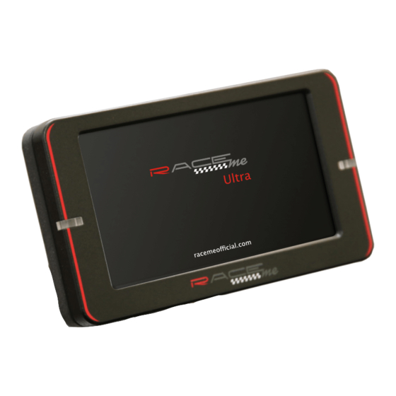
- Page 2 The following picture depicts all the parts of the Ultra and their respective names. Each Ultra has a Micro SD included and is preinstalled in the top left corner of the display. For Update purposes, it can be removed by lightly pushing down on it until it until it unclicks from the socket.
- Page 3 Plug the micro USB cord into the back of the display, taking special care in the orientation of the cord. There is a “B” printed on one side of the cord plug, which must be facing the bottom of the monitor. Improper orientation of this cord will result in a damaged cord and/ or socket and will NOT be covered under warranty.
- Page 4 The Controller then connects to the Communication Module via a DB-15 serial connection. This is an interference fit connection. What this means is that when the two boxes are pushed together, the tight fit of the plastic cases will hold them together. The DB-15 Connector on the other side of the Communication module will accept the OBD2 cable.
- Page 5 firewall. The recommended area for this is the shift cable boot to the left of the steering column as shown in the following picture. Once in the engine bay, locate the datalink connector. The location of the Datalink connector is the same in all trucks from 2010 –...
- Page 6 This will complete the connections of the Ultra. Turning the ignition to the “Run” position will “wake up” the Ultra. The Tuner is now ready to program the ECM. For further information on the programming process, please see our Programming manual.
Need help?
Do you have a question about the Ultra and is the answer not in the manual?
Questions and answers