Advertisement
Quick Links
BVO Model Number Information
Range
Fittings
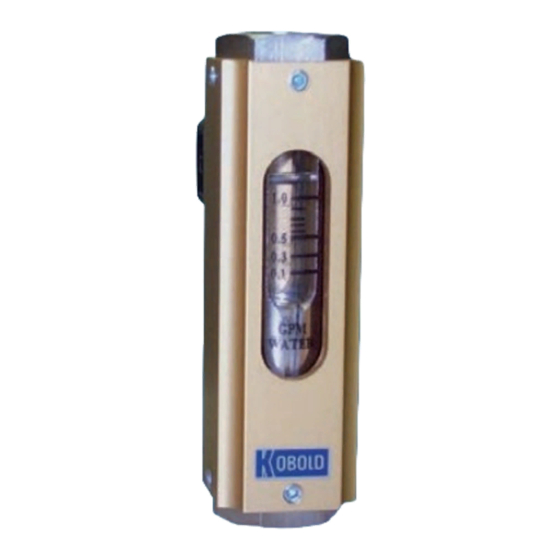
GPM Water
NPT
0.1-1.0
1/4"
0.2-2.0
1/4"
1.0-5.0
1/2"
1.0-13
1"
Option Suffix "U" SPDT switch in place of the N/O switch
Installation Precautions
User's Responsibility for Safety: it is the user's responsibility
to select the instrument that is appropriate for the application, to
install it per these installation instructions, to perform tests of
the installed system, and to maintain all components. The
failure to do so could result in property damage or serious
injury.
Temperature and Pressure: The BVO is designed for use in
application temperatures from -10 to 212°F, and pressures to
145 PSIG. Operation outside these limitations will cause
damage to the unit and possible personal injury.
Flammable, Explosive and Hazardous Applications: The
switch provided with the BVO is not of an explosion proof
design. If the unit is to be used in an area where risk of
explosion exists, the switch must be connected via an
appropriately selected and installed intrinsic safety barrier.
Specifications
Accuracy:
±12% of full scale
Repeatability:
±2% of full scale
Media:
Water-like liquids
Fittings:
NPT
Wetted Parts:
Brass Meters:
Nickel-Plated Brass, Buna-N, Glass
SS Meters:
304 SS, Viton, Glass
Temperature Range: -10 to 212°F
Maximum Pressure:
145 PSIG
Flow Direction:
Vertical, flow bottom to top
KOBOLD Instruments Inc.
1801 Parkway View Drive
Pittsburgh, PA 15205
1-412-788-2830
Fax: 1-412-788-4890
www.koboldusa.com
Pressure Loss
@ Max Flow
Brass
PSIG
0.9
BVO-6102
1.4
BVO-6106
1.1
BVO-6116
2.1
BVO-6150
Model Number
304 SS
BVO-6202
BVO-6206
BVO-6216
BVO-6250
Material Compatibility: Check your model number with the
wetted materials specification. Make sure that the model
which you have selected is chemically compatible with the
application liquids.
Proper Installation and Handling: Use a proper sealant with
all installations. Never overtighten the unit within the fitting.
Never use the housing to thread the unit into its fitting.
Always use only an appropriate sized wrench on the hex
portion of the body. Ensure that the piping is rigidly supported
at the inlet and outlet of the meter. Always check for leaks
prior to system start-up.
Make a Fail-safe System: Design a fail-safe system that
accommodates the possibility of switch failure as well as
operator error. In critical applications, KOBOLD recommends
the use of redundant backup systems and alarms in addition
to the primary system.
N/O Switch Specifications:
Max. Voltage:
Max. Current:
Max. Power:
Switching Hysteresis:
SPDT Switch Specifications:
Max. Voltage:
Max. Current:
Max. Power:
Switching Hysteresis:
BVO Series
Flowmeter and Switch
Installation Instructions
240 VAC, 200 VDC
1.5 Amp AC, 1.0 Amp DC
50 VA, 50 Watts
4-8 mm of float travel
240 VAC
0.8 Amp AC
30 VA
4-8 mm of float travel
bvo_manual FM Rev. 5/25/06
Advertisement

Related Manuals for Kobold BVO Series


Summary of Contents for Kobold BVO Series
-
Page 1: Installation Precautions
BVO is not of an explosion proof operator error. In critical applications, KOBOLD recommends design. If the unit is to be used in an area where risk of... -
Page 2: Electrical Connections
Electrical Connections Normally Open SPST Contact SPDT Contact Adjusting the Switch Setpoint Adjusting to Switch on Increasing Flow Adjust the setpoint as follows: Loosen the hold-down screws on the reed contact housing. Slide the contact upwards along its rail until it reaches the stop. Open the medium feed line and set flow to desired volume.