Table of Contents
Advertisement
Advertisement
Table of Contents

Related Manuals for Berges ACM-D2 Series


Summary of Contents for Berges ACM-D2 Series
- Page 1 Operating manual...
-
Page 3: Table Of Contents
BERGES electronic Table of contents Safety notes............3 1.1. - Page 4 Notes ..............59 Operating manual ACM-D2 Document: ACM/D2A-STD-E/A07 Edition: 29.05.1998 © 1998 BERGES electronic s.r.l. All rights reserved. ArtNr: 38005000EN Operating manual ACM-D2 29.05.98...
-
Page 5: Safety Notes
Conversions or changes carried out on or in the inverter and its components and accessories without express authority render all warranty claims null and void. Please contact BERGES if any conversions or changes are necessary, particularly in relation to the electric components. - Page 6 BERGES electronic The components of the power section and specific elements of the control section are connected to the voltage mains when the inverter is connected to the mains voltage. Touching these components involves mortal danger! Isolate the inverter from the mains before removing the front panel or the housing (e.g. by removing or deactivating on-site fuses or by deactivating a master switch isolating all poles etc.).
-
Page 7: Use Of The Inverter In Accordance With Its Intended Purpose
Only personnel informed about the functions and hazards of the inverter may be employed for the purposes of operation, maintenance and repair. Only items expressly approved by BERGES (e.g. mains filters and chokes etc.) may be used as accessories. The installer of the system is liable for any damage resulting from the use of accessories that have not been approved expressly by BERGES. -
Page 8: Technical Data (Input Voltage 1 X 220
BERGES electronic 4. Technical data (input voltage 1 x 220...240V) ACM-D2 Inverter 0.37kW 0.55kW 0.75kW 1.1kW 2.2kW Motor output 0.37 0.55 0.75 Output power 0.75 Rated device current 200% × 180 s (+/-15%) Overload capacity Output voltage 3 x 0...U (max. -
Page 9: Technical Data (Input Voltage 3 X 380
BERGES electronic 5. Technical data (input voltage 3 x 380...415V) ACM-D2 Inverter 0.75kW 1.1kW 1.5kW 2.2kW 3.0kW 4.0kW 5.5kW Motor output 0.75 Output power Rated device current 11.7 200% × 180 s (+/-15%) Overload capacity Output voltage 3 x 0...U (max. -
Page 10: Technical Data (Input Voltage 3 X 380
BERGES electronic 6. Technical data (input voltage 3 x 380...460V) ACM-D2 Inverter 7.5kW 11.0kW 15.0kW 22.0kW 30.0kW 37.0kW Motor output 11.0 15.0 22.0 30.0 37.0 Output power 16.5 22.5 Rated device current 15.6 22.5 200% × 180 s (+/-15%) Overload capacity Output voltage 3 x 0...U... -
Page 11: Power-Derating In Function Of The Switching Frequency
BERGES electronic 7. Power-derating in function of the switching frequency ACM-D2 0,37-2,2kW/230V ACM-D2 1,1-4,0kW/400V ACM-D2 5,5kW/400V ACM-D2 7,5kW/400V ACM-D2 11kW/400V (kHz) ACM-D2 15kW/400V ACM-D2 22-37kW/400V (kHz) Nominal power Output power Switching frequency Ambient conditions: T = 45°C 29.05.98 Operating manual ACM-D2... -
Page 12: Dimensional Data Acm-D2 0.37 Kw - 5.5 Kw
BERGES electronic 8. Dimensional data ACM-D2 0.37 kW - 5.5 kW Additional mounting bracket: Only for ACM-D2 5,5kW ACM-D2 0.37 - 2.2kW ACM-D2 0.75 - 5.5kW Dimensions (in mm) ACM-D2 (1x230V) ACM-D2 (3x400V) 0.37 0.55 0.75 1.1 1.5 2.2 0.75 1.1 1.5 2.2 3.0 4.0 5.5... -
Page 13: Dimensional Data Acm-D2 7.5 Kw - 22.0 Kw
BERGES electronic 9. Dimensional data ACM-D2 7.5 kW - 22.0 kW ACM-D2 7.5 - 11.0kW ACM-D2 15.0 - 22.0kW Dimensions (in mm) ACM-D2 (3x400V) 11.0 15.0 22.0 54.25 54.25 Ø7 Ø7 Ø6 Ø6 154.75 154.75 29.05.98 Operating manual ACM-D2... -
Page 14: Dimensional Data Acm-D2 30.0 Kw - 37.0 Kw
BERGES electronic 10. Dimensional data ACM-D2 30.0 kW - 37.0 kW ACM-D2 30.0 - 37.0kW Dimensions (in mm) ACM-D2 (3x400V) 30.0 37.0 35.5 65.5 98.5 Ø7 Ø7 ACM-D2 30.0 - 37.0kW Operating manual ACM-D2 29.05.98... -
Page 15: Installation Examples
BERGES electronic 11. Installation examples 11.1. Exemple 1: ACM-D2 0.37 kW - 2.2 kW (1 x 230V) 1) The GND terminals (10, 12 and 14) are floating and serve, among other things, as the reference potential for shielded cables of the control inputs. This potential must be grounded directly either at the control side (PLC or similar) or at the inverter (PE to one of the terminals 10, 12 or 14). -
Page 16: Exemple 2: Acm-D2 0.75 Kw - 37.0 Kw (3 X 400V)
BERGES electronic 11.2. Exemple 2: ACM-D2 0.75 kW - 30 kW (3 x 400V) 1) The GND terminals (10, 12 and 14) are floating and serve, among other things, as the reference potential for shielded cables of the control inputs. This potential must be grounded directly either at the control side (PLC or similar) or at the inverter (PE to one of the terminals 10, 12 or 14). -
Page 17: Installation
−5 °C to +45 °C and at a relative humidity of up to 90%. Formation of condensation must be avoided! Please contact BERGES if the above values are exceeded. A heat build-up at the inverter during operation must be prevented. The internal air circulation may possibly be insufficient if the unit is installed in a control cabinet with a small volume. -
Page 18: Motor Connection
BERGES electronic Frequency inverters must not be connected via a residual-current-operated circuit- breaker as the sole protective measure! The single exception below permits connection of a frequency inverter via a residual-cur- rent-operated circuit-breaker as the sole protective measure: Installation of a residual-current-operated circuit-breaker of the newest design for frequency in- verters up to 4kVA (input voltage 1x230V) with MOBILE connection.This residual-current-... -
Page 19: Interference Suppression Measures/Emc (Electromagnetic Compatibility)
Other measures may be necessary to reduce or suppress interference if the mains voltage is ‘‘contaminated’’. No generally valid recommendations can be given in such cases. Please consult BERGES if all recommended interference suppression measures should not produce the desired result. -
Page 20: Mains Back-Up Fuses
BERGES electronic Other loads connected to the mains may produce voltage spikes that may interfere with functioning of the inverter or may even damage it. Chokes or main filters can be used on the mains side to protect the inverter against voltage spikes (resulting from switching large loads to the mains, for example). -
Page 21: Series Autotransformer
BERGES electronic 12.6. Series autotransformer A series autotransformer is dimensioned as follows (guide value): Rated inverter output × 2 = Transformer output in kVA. Attention must be paid to the voltage increases in no-load condition when using isolating transformers. 12.7. Ventilation For all inverters, the permissible ambient temperature of 45 °C must not be exceeded. -
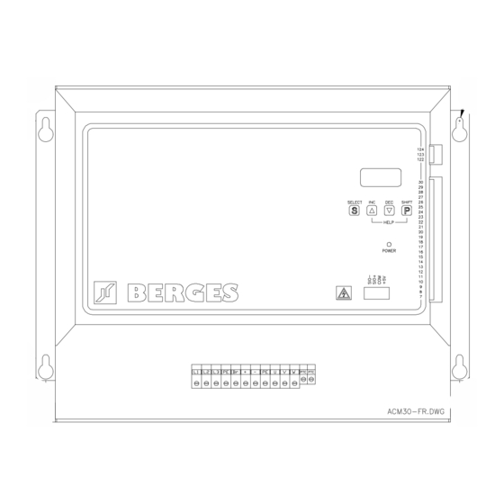
Page 22: Control Terminals
Input high, corresponds to EIA Standard RS 485. SIO+ Input low, corresponds to EIA Standard RS 485. SIO− Serial interface Ground (earth-free). Power supply (for BERGES options only). Inverter status Error Normal operation : 123, 124 closed. signalling Error : 122, 123 closed. -
Page 23: Power Terminals
BERGES electronic Configuration terminal 17: ACM-D2 0.37 - 22.0kW ACM-D2 30.0 - 37.0kW Control board Control board Digital inputs: max. input voltage: + 30V DC Low - level : 0...1V High - level : 4...30V Error signalling relay: 250V AC 1A... -
Page 24: Commissioning And Settings
BERGES electronic 13. Commissioning and settings 13.1. General information The following points must be observed before commissioning: • Corresponding of the mains voltage with the input voltage of the inverter. • Check that the motor has the correct type of connection (star-delta connection). -
Page 25: Operating Functions
BERGES electronic 14. Operating functions 14.1. General The ACM-D2 inverters are pre-programmed to run a 4-pole AC-induction motor. In many cases no additional programming is required. 14.2. Control panel All functions of the inverter can be controlled by way of the ACM-D2 control panel. The 4 input keys allow control of the motor and direct parameter programming. -
Page 26: Display
BERGES electronic 14.3. Display An eight-position alphanumeric display provides the user with all important information, such as inverter status messages and information on possible errors or faults and parameter setting values.The language for the display readout is selectable. 14.4. Help - function and language - select When pressing SHIFT and INC, on the display appears a scrolling Help-text concerning the currently active function. -
Page 27: Warnings
BERGES electronic 14.6. Warnings Message Description undervol The mains has been reached the Undervoltage Limit. overload The output current has almost reached the type-specific limit The set limit value for the output current has been exceeded. The output HYST frequency is reduced step-by-step until the output current falls below the limit value again (see TAB1, SUB IMOT, function S-INT =4). -
Page 28: Hardware Error Messages
BERGES electronic 1) Inverter stopped. Automatic error reset as soon as the link voltage rises above the undervoltage value. 2) Inverter stopped. If the AUTORESET function is activated (see TAB3, SUB XPAR, function SW3), a reset is possible by setting or the START/STOP input, or the ENABLE input, or by setting the setpoint to zero. -
Page 29: Input Circuit
BERGES electronic 14.9. Input circuit 29.05.98 Operating manual ACM-D2... -
Page 30: Programming Acm-D2
BERGES electronic 15. Programming ACM-D2 15.1. Program structure Operating manual ACM-D2 29.05.98... - Page 31 BERGES electronic 29.05.98 Operating manual ACM-D2...
-
Page 32: Program Level Tab1
BERGES electronic 15.2. Program level TAB1 1 33.62Hz TAB1 Function 1: Indication of the output frequency The standard display of function 1 shows the inverter operating frequency in Hertz. This can be changed to other operating data by the setting of TAB3, func. DIS. - Page 33 BERGES electronic 2.5s TAB1 Function 5: Acceleration time ramp 1 This parameter sets the time to accelerate the motor from 0 to 50 Hz. Range: Use the following formula to determine the proper time for other frequencies: 0.05...1000 sec. TACC Tx=50∗...
- Page 34 BERGES electronic TAB1 Function 8+: Dynamic BOOST This parameter may be programmed to provide additional torque boost during accele- Range: 0...50% ration. Values are in percent (%) of line input voltage. Default: 0% 8− TAB1 Function 8−: U/f-ratio reduction during deceleration This parameter defines the motor voltage reduction during deceleration to compensate Range: 0...20%...
- Page 35 BERGES electronic JOG OFF TAB1 JOG function: JOG Mode and motorpotentiometer If the JOG is enabled the output frequency may be controlled by the keyboard (INC and DEC buttons). The frequency control in the JOG Mode is possible after the enable operation is done and by returning to TAB1, function 1.
- Page 36 BERGES electronic u 10.0Hz TAB1 Function u: Frequency threshold FX2 This parameter is used to program a frequency threshold FX2. The outputs OC1, OC2 Range: 0...Fmax or REL may be programmed to signalize motor speed equal or greather than FX2. The threshold FX2 can also be used for automatic ramp switching (see TAB3, SUB XPAR, func.
- Page 37 BERGES electronic S-INT TAB1 Function S-INT: Inverter behaviour at the current limit SUB IMOT This parameter defines the inverter behaviour when the output current exceeds the pro- grammed limit: Range: 0...4 0: Internal handling disabled. Default: 0 1: The inverter is immediatly stopped.
- Page 38 BERGES electronic SUB SLIP TAB1 Submenu slip compensation (Only with software D2A-STD) Submenu containing the slip compensation functions. To enter the submenu press both SHIFT and SELECT simultaneously. s 0.0Hz TAB1 Function s: slip compensation frequency The frequency with wich is enlarged the inverter output frequency when the inverter ra- SUB SLIP ted current is reached (100%).
- Page 39 BERGES electronic SUB FFIX TAB1 Submenu preset frequencies The parameters of this submenu are used to set the three preset speeds. The sign of the parameter value defines the rotating sense of the motor (+ forward; - reverse). In order to permit control of the direction of rotation of the preset frequencies via termi- nal 15, it is necessary to deactivate the sign + or −...
- Page 40 BERGES electronic TAB1 Function DC: DC brake voltage This parameter controls the amount of DC voltage applied to the motor windings du- Range: 0...50% ring activation of the DC-brake. The DC-brake is activate during the time when term. 30 is activated and after deactivation of term. 30 for the time set by TAB1, func.
-
Page 41: Program Level Tab2
BERGES electronic DEFAULT TAB1 Recall factory settings The original factory settings for all parameters can be restored by pressing both INC and DEC simultaneously for 5 sec. A blinking "DEFAULT" indicates that recalled para- meters are not stored. To store the recalled parameter values into the non volatile in- verter memory execute the SAVE - function. - Page 42 BERGES electronic FILTER 3 TAB2 Function FILTER: Speed reference filter Range: 0...6 The speed reference signal can be filtered by a digital filter. The line constant of the fil- ter is set by this parameter. Default: 3 SUB LOG TAB2...
- Page 43 BERGES electronic TAB2 Function REF: Speed reference selection This parameter is used to define the type of external speed reference signal the inver- SUB REF ter will be receiving from the corresponding control inputs. In order to work properly the jumpers must be set corresponding to the selected speed reference type.
- Page 44 BERGES electronic AO 0% TAB2 Function AO: Fine tuning output frequency (Only with software D2A-STD) The output frequency can be modified with an analog signal (0...10V) applied at the SUB REF configurable analog input (terminal 17; configuration mode 1, see page 21). In this Range: 0...100%...
- Page 45 BERGES electronic BrLim 0 TAB2 Dynamic braking protection The dynamic braking circuit can be protected from overload activating this protection Range: 0...15 function. If the braking power exceeds the programmed limit, the motor is ramped down to zero and the inverter is stopped. The programmed value corresponds to the max.
-
Page 46: Program Level Tab3
BERGES electronic PASS 000 TAB2 Function PASS: PASSWORD If a password has been assigned (PASSWORD <> "000"), to enter the functions SECUR and SET PASS, the access code must be entered in this function. SECUR. 0 TAB2 Function SECUR: Security code Setting of the requested security level: Range: 0...2... - Page 47 BERGES electronic SUB DIAG TAB3 Submenu DIAGNOSTICS SUB DIAG SOLL xx Speed reference signal indication on term. 8 or 29 (dig. 9 bit 0...511) ANA xx Input AN-IN/OUT term. 17 (configuration mode 1, see page 21) PortE Status of port E...
- Page 48 BERGES electronic Fm 50.0Hz TAB3 Function Fm: Full scale frequency value Range: 5...650 Hz (10...1300 Hz *) This parameter defines the full scale (10V) frequency value on the analog meter output (term. 13). Default: 50 Hz *Vers.D2A-1300-xxx SUB XPAR TAB3 Submenu extended parameters Setting of eigth extended inverter parameters.
- Page 49 BERGES electronic TAB3 Function SW4: Fmin configuration This function defines the inverter behaviour at Fmin. Two different settings are possi- SUB XPAR ble (see the following diagramm). Range: ON, OFF Fmin : Value TAB1, function 4. Default: ON : Output frequency.
- Page 50 BERGES electronic SW8 OFF TAB3 Function SW8: "S" ramp S-form acceleration and deceleration ramps are selected with this function. SUB XPAR The ramp characteristic is calculated on the basis of the highest frequency value ente- red in Fmax (TAB1, function 3), or FFIX1--FFIX3 (TAB1, SUB FFIX) and is symmetri- Range: ON, OFF cal with respect to the point of inflection.
- Page 51 BERGES electronic TAB3 Function REL: Relay output configuration (term. 19, 20) This function defines the condition which will cause the auxiliary relay to operate. It may be programmed for one of 11 conditions. The sign defines if the relay closes or opens at condition.
- Page 52 BERGES electronic −0 TAB3 Function OC2: Open collector output 2 (term. 22) Function OC2 defines the condition which will cause the open collector output OC2 to ope- rate. It may be programmed to one of 11 conditions. The sign defines the output level for OC1 (ACTIVE or NOT ACTIVE) at condition.
- Page 53 BERGES electronic BERGES TAB3 Power-on message The 8-character power-on message which is displayed during the self-test is program- SUB DISP med in this function. Range: Cursor positioning with the SHIFT key. Display characters Character selection with the keys INC and DEC.
-
Page 54: Braking Chopper Acm - D2
BERGES electronic 16. Braking chopper ACM - D2 16.1. Braking chopper 0.37 kW - 1.1 kW (1 x 230V) The inverters ACM-D2 0.37 - 1.1 kW are equipped as standard with an internal dynamic braking chopper. Braking resistance: 50 Ohm/50 Watt. -
Page 55: Accessories
BERGES electronic 17. Accessories 17.1. Programming key The programming key permits the parameter values of the inverter to be read out, read in and saved in a very simple way. Loading the parameter values of the inverter in the programming key: •... -
Page 56: Software Keysoft
BERGES electronic 17.2. Software KEYSOFT The software KEYSOFT permits transfer of parameter values from KEY to the PC and vice versa. Data can be saved on the PC. System requirements: • Personal computer AT-compatible with serial interface RS 232 (COM1 or COM2). -
Page 57: Faults And Remedies
BERGES electronic 18. Faults and remedies The inverter is equipped with devices for error detection and error signalling. Error signals are routed to the error signalling relay (250V AC 1A; terminals 122, 123 and 124) and shown on the display. -
Page 58: Functions Of Acm-D2
BERGES electronic 19. Functions of ACM-D2 Function Works Customer Page setting Adjustment range setting Design. Description (Default) Output frequency indication Motor voltage indication 6...650 Hz Maximum output frequency 50 Hz (12...1300 Hz *) Minimum output frequency 0 Hz 0...Fmax Acceleration time ramp 1 2.5 sec. - Page 59 BERGES electronic Function Works Customer Page setting Adjustment range setting Design. Description (Default) CLIP Clipping 0...15 FILTER Speed reference filter 0...6 ENABLE input HIGH - LOW REVERSING input HIGH - LOW - OFF START/STOP input HIGH - LOW PRESET FREQ. SEL. 1 input HIGH - LOW - OFF PRESET FREQ.
- Page 60 BERGES electronic Function Works Customer Page setting Adjustment range setting Design. Description (Default) Speed reference signal SOLL (terminal 8 or 29) Input AN-IN/OUT Port E Status PortE Port A Status Port A Status U27 Status U31 Status U1 Status U2...
-
Page 61: Notes
BERGES electronic 20. Notes 29.05.98 Operating manual ACM-D2... - Page 62 BERGES electronic...
- Page 64 Berges electronic s.r.l. Berges electronic GmbH Postfach 1140 •D-51709 Marienheide Industriestraße 11 Tel: 0 22 64/17-0 •Fax: 0 22 64/1 71 25 I-39025 Naturns (BZ) Tel: 0473/671911 Fax: 671909 Telex: 8 84 116...
Need help?
Do you have a question about the ACM-D2 Series and is the answer not in the manual?
Questions and answers