Table of Contents
Advertisement
Quick Links
Advertisement
Table of Contents

Related Manuals for sewerin EX-TEC PM 580


Summary of Contents for sewerin EX-TEC PM 580
- Page 1 EX-TEC PM 580/550/500/400 ® Operating Instructions...
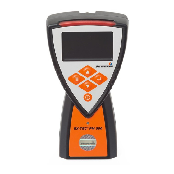
- Page 2 Device Signal light Display Menu key Up key Enter key Down key ON/OFF key Buzzer Fig. 1: Front view Gas input Filter fastener Belt clip with D-ring Battery compartment Fig. 2: Rear view...
- Page 3 Display Application Measurement value 1: – Bar graph with quasi-logarithmic scale – Measurement value, gas, unit Measurement value 2: – Measurement value, gas, unit Remaining capacity (disposable/rechargeable battery) Fig. 3: Display in measuring mode - Structure application Fig. 4: Display in measuring mode Left image: Warning application Right image: Measuring application...
- Page 4 Illustration of warnings in this document DANGER! Risk of personal injury. Will result in serious injury or death. WARNING! Risk of personal injury. Can result in serious injury or death. NOTICE! Risk of damage to property.
-
Page 5: Table Of Contents
Introduction ................1 Information about this document ..........1 Purpose ..................2 Intended use ................2 Improper use ................2 Safety information ..............3 1.6 Qualification of users ..............5 Product description ..............6 Product variants ................6 Application options ..............7 2.2.1 Detectable gases ..............7 2.2.2 Applications ................8 Features ..................9 2.3.1 Sensors ..................9 2.3.2 Gas types ................ - Page 6 3.3.3.2 Switch from menu or the measuring menu into measuring mode ...............25 3.3.3.3 Select a menu item in a menu...........26 3.3.3.4 Cancel the action or process..........26 3.3.4 Scrolling ................26 3.3.5 Select values ................27 3.3.6 Queries - perform action or don’t perform an action ....27 3.3.7 Lists - view detailed information ...........28 3.3.8...
- Page 7 Suitable environment ..............53 Device inspection ..............53 6.4.1 Ways of carrying out the procedure ........53 6.4.2 Frequency and due date ............54 6.4.3 Variants of the guided device inspection (standard and ECO) .............55 6.4.4 Features ................56 6.4.5 Presentation of results ............57 6.4.6 Required accessories ............58 6.4.7 Perform a device inspection ..........58...
- Page 8 Faults and problems .............76 Error messages ...............76 Warning messages ..............77 Resolution of problems ............77 8.3.1 Device has sucked water in ..........77 8.3.2 Temporary zero point cannot be set ........79 Appendix ................80 Technical data .................80 Sensors ...................83 9.2.1 Infrared sensors ..............83 9.2.2 Semiconductor sensor ............86 9.2.3...
-
Page 9: Introduction
German version is authoritative. Right of reproduction No part of this document may be edited, duplicated or circulated in any form without the express consent of Hermann Sewerin GmbH. Registered trademarks Registered trademarks are generally not indicated in this docu- ment. -
Page 10: Purpose
Purpose The device is a portable gas concentration measuring device for detection, measuring and warning. The device can be used for: ● Pinpointing leaks in gas pipes that are not underground ● Assessment of the risk of explosion in work areas ●... -
Page 11: Safety Information
− Then perform a device inspection. ● Protect the ports and sockets against dirt, and electrical ports in particular against moisture. For the PM 400 SEWERIN also recommends: If the LEL sensitivity devi- ates by more than 20%, replace the CC sensor. 1 Introduction │ 3... - Page 12 ● Handle test gases in a professional manner. Sensors ● Have sensors replaced by SEWERIN Service when their ser- vice life has expired. ● SEWERIN recommends: Perform a device inspection when the device has been exposed to gas concentrations above the end of measuring range.
-
Page 13: Qualification Of Users
− Specialists are permitted to perform device inspections and adjustments. They can evaluate the results. Competent person SEWERIN service personnel and people trained by SEWERIN are competent persons. − Competent persons have knowledge of the applicable regula- tions and guidelines as well as the tasks and functions of gas concentration measuring devices. -
Page 14: Product Description
Product description Product variants The following product variants of the device are available: ● Ex-TEC PM 580 (for short: PM 580) ● Ex-TEC PM 550 (for short: PM 550) ● Ex-TEC PM 500 (for short: PM 500) ● Ex-TEC PM 400 (for short: PM 400) Each product variant has certain basic device features as stand- ard. In addition, there are different device features for each prod-... -
Page 15: Application Options
Application options 2.2.1 Detectable gases The device may be used to measure the following gases: PM 580 PM 550 PM 500 PM 400 Methane CH × × × × Propane C Nonane C – – – Carbon dioxide CO Oxygen O Carbon monoxide CO Hydrogen sulphide H –... -
Page 16: Applications
2.2.2 Applications The following applications are differentiated for working with the device (/3/): Application Activities Warning – monitoring of work areas – warning of toxic gas concentrations – warning of lack of oxygen/excessive oxygen – warning of explosive gas concentrations Measuring – demonstrating gas purity / absence of gas in gas pipes Structure –... -
Page 17: Features
Features 2.3.1 Sensors The sensors included as device features depend on the product variant. The following sensors are included as standard or as options: Sensor Gas/gas type PM 580 PM 550 PM 500 PM 400 × × × – × –... - Page 18 Technical information about the sensors, including their meas- urement ranges, can be found in section 9.2. Information about electrochemical sensors Very high gas concentrations can reduce the lifetime of electro- chemical sensors. Information about semiconductor sensors and catalytic combustion sensors These sensors are sensitive to external influences.
-
Page 19: Gas Types
2.3.2 Gas types By default the device is set up for gas type methane CH However, the sensors fitted to a device as standard (section 2.3.1) can be set up for other gas types or for additional gas types. The following gas types can be set up: Gas type PM 580 PM 550 PM 500 PM 400 ×... -
Page 20: Alarm Signals
Signals are emitted at: ● Alarm ● Error (error message) ● Device inspection or inspection due ● Warning, information ● Switch device on and off There are also signals as: ● Operating signal ● concentration-dependent signal 2.3.3.2 Alarm signals Warning alarms are emitted if the concentration of one or more gases exceeds certain limit values (alarm thresholds). -
Page 21: Operating Signal
Detailed information about the alarms, including the acknowl- edgement options, can be found in section 9.4. 2.3.3.3 Operating signal Note: An operating signal is available only in the Warning and Struc- ture applications The operating signal indicates that the device is working properly. The signal is emitted regularly every 20 seconds. -
Page 22: Belt Clip And Short Probe
The gas that is sucked in flows through two filters directly behind the gas input. The filters prevent contamination or moisture from entering the device and thus reaching the sensitive sensors. ● dust filter traps solids, particularly dusts ● hydrophobic filter serves as a water barrier Fig. 5: Hydrophobic filter (left) and dust filter (right) The filters must be changed regularly. Information on the fre- quency and procedure for changing can be found in section 3.11. 2.3.6 Belt clip and short probe The device comes with a belt clip and the PM 5 short probe. -
Page 23: Additional Probes
The PM 5 short probe is included in the scope of delivery (sec- tion 2.3.6). Other probes can be purchased as accessories. SEWERIN will be happy to advise you on selecting suitable probes. Note: Probes that are used must be visually inspected as part of the device inspection process. - Page 24 In the menu the user can: ● Perform actions ● Perform settings ● View information ………… Warning Start recording/ Stop recording ………… Measuring Set zero point Information application ………… Structure PIN code ………… ………… Settings Adjustment Warning Measuring Structure Restore …………...
-
Page 25: Units For Concentration Data
Units for concentration data 2.6.1 Selectable units (warning) In the Warning application, the measurement value for the flam- mable gases can be displayed either % LEL or % vol. as the unit. The device is supplied set to the % LEL unit. The unit can be changed using the GasCom software. -
Page 26: Operation
Operation Switching on the device WARNING! Risk to life due to contaminated ambient air If the device is switched on in a contaminated environ- ment , incorrect measurement values may be displayed in measuring mode. ● Switch on the device only in clean air. Each switch-on process is linked to activation of the buzzer, sig- nal light and display. - Page 27 Note: If the message Start sensors … appears, it means the sensors are still warming up. During this warm-up time, no operating sig- nal is emitted and no actions can be performed. 1. Make sure the ambient air is clean. 2.
- Page 28 Fig. 9: Sequence of start images during start-up The logo can be customised us- ing the GasCom software. Fig. 10: Display of the device inspections that are due and the inspection that is due (Only displayed if the guided device inspection is activated and a device inspection or inspection is due.) Fig.
-
Page 29: Switch Off Device
Fig. 12: Device ready for use with the pre- set application (here: Warning application) Special features at initial start-up The language of the user interface must be set once at initial start-up. The setting is performed in association with the start images (Fig. -
Page 30: Navigating
Cancel switch-off Whilst the message Device switching off … is displayed, the switch-off process can be cancelled. ● Release the ON/OFF key before the message disappears. The device returns again to measuring mode. Navigating 3.3.1 Orientation aids on the display By means of orientation aids the user can identify the program situation in which the device finds itself or what action is required. - Page 31 The symbols in the status bar give an indication of the current situation. The remaining battery capacity is always displayed. Fig. 15: Status bar (black) Left image: Status bar above the information area Alongside: Examples of information about the current situation (here: Remaining capacity, Device inspection due, Recording) Messages...
-
Page 32: Key Functions
3.3.2 Key functions The following actions can be performed using the keys: Actions ● Switching – the device on and off ● Changing – from measuring mode to the top menu level ● Acknowledge – a message ● Change back – a menu level ●... -
Page 33: Switch Between Levels
3.3.3 Switch between levels 3.3.3.1 Changing from measuring mode to menu or measuring menu WARNING! Risk to life due to absence of alarms The device emits alarms only when in measuring mode. As soon as you switch from measuring mode to the menu, no alarms are triggered. -
Page 34: Select A Menu Item In A Menu
3.3.3.3 Select a menu item in a menu The device shows a menu. 1. Using the arrow keys, select the desired menu item. 2. Press the Enter key. The menu item appears. 3.3.3.4 Cancel the action or process The display shows any menu level. 1. -
Page 35: Select Values
3.3.5 Select values Values must be selected from a list for certain settings. Entering the PIN code also works in this way. Fig. 18: Examples of selecting values Left image: Entering the PIN code for the settings Right image: PPM threshold The program situation requires the selection of values. -
Page 36: Lists - View Detailed Information
Fig. 19: Examples of queries Left image: Query with the preset value that an action should be performed Right image: Query with the preset value that an action should not be performed The display shows a query. 1. Check the preset values for the response. 2. - Page 37 If a comment is selected from the list, it can either be accepted unchanged or modified. Fig. 20: List of comments top line: write new comment (Write symbol) below: existing comments A comment can contain letters, spaces, numbers and special characters (dot, comma, dash). The entry can be a maximum of 20 characters long.
-
Page 38: Start, Stop, Save Recording
The following keys and symbols can be written: Actions ● Select – a character or symbol ● Use – a character If the action is performed at the end of the string, a following character can then be added. ● Trigger –... -
Page 39: Start Recording
Each recording is automatically saved when it stops and is then listed in the protocols. A comment can be saved for each record- ing together with the measurement values. 3.4.1 Start recording The device is in measuring mode. 1. Press the Enter key. The device switches to the measurement menu. -
Page 40: Stop Recording And Save It With A Comment
3.4.3 Stop recording and save it with a comment The device is in measuring mode. A recording is running. 1. Press the Enter key. The device switches to the measurement menu. 2. Select Stop recording. 3. Press the Enter key. The following query appears: Stop and save recording? 4. -
Page 41: Set Zero Point
WARNING! Risk to life when using de-adjusted or faulty devices in the Warning application A device inspection must be performed regularly when the device is used as a gas warning instrument. This applies both when the Warning application is preset and when switching to this application from another application. - Page 42 In contrast to performing a zero point adjustment, the temporarily set zero point is not saved. Note: If the zero point deviates repeatedly from the target values, ad- just the device. Fig. 25: Set zero point Target values for the zero point Content in clean air Target value on the device 0 % LEL...
-
Page 43: Change Gas Type
If the zero point cannot be set successfully, you will find informa- tion in section 8.3.2 about how to solve the problem. Change gas type The device always switches on set to the preset gas type. During operation you can temporarily switch between all gas types for which a device is set up. Fig. -
Page 44: Changing The Settings On The Device
Changing the settings on the device Some settings can be changed directly on the device. Fig. 27: Settings Detailed information about the settings that can be changed on the device can be found in section 4.3. WARNING! Risk to life due to absence of alarms The device emits alarms only when in measuring mode. -
Page 45: Concentration-Dependent Signal (Structure)
Concentration-dependent signal (structure) In the Structure application, there is a concentration-dependent signal for the measurement of hydrocarbons. This signal can be used for audible evaluation of the measurement value. The signal is activated when a specified concentration value is exceeded. − As the concentration increases, the signal becomes louder. −... -
Page 46: Leak Test When Using Probes
3.10 Leak test when using probes If the device is used with probes, the leak-tightness of the gas path and the probe or probe hoses must be checked regularly. The gas path at the gas inlet is sealed off for the test. The device must respond to this with an error message. Frequency The leak test must be performed at least quarterly. Special features ●... -
Page 47: Changing The Filter
3.11 Changing the filter The filter seal seals the filter opening. The dust filter is located in the filter seal, the hydrophobic filter is located in the filter opening (Fig. 28). Fig. 28: Position of filters (schematic representation) from top to bottom: Filter fastener with 2 O-rings Dust filter O-ring Hydrophobic filter The filter fastener has lugs of two different widths. It is a close fit in the filter opening. Fig. 29: Filter fastener with lugs of two dif- ferent widths (view from above) Frequency The frequency of the filter replacement is greatly dependent on the frequency of device usage and the ambient conditions dur-... - Page 48 The filters must be replaced if they exhibit: ● visible contamination ● mechanical damage ● contact with water If none of the events occurs, the filters must be replaced after 12 months at the latest. Checking the filters The dust filter contamination can be tested from the outside by inspection through the transparent filter fastener. To check the condition of the filters more precisely, the filter fas- tener must be unscrewed. Note: Once a hydrophobic filter has been taken out it must not be re- placed. Recommended tools ● Coin for turning the filter fastener ● Tweezers for removing and inserting the hydrophobic filter and O-ring Changing the filter NOTICE! Risk of contamination New filters, i.e. filters not yet used, must be handled carefully to prevent mechanical damage.
- Page 49 The device is switched off. 1. Turn the filter fastener anticlockwise until it reaches the stop. 2. Pull off the filter fastener. 3. Within the filter fastener: Change the dust filter a) Remove the used dust filter. b) Insert a new dust filter. Press the filter gently into the filter fastener. 4. Within filter opening: Replace the hydrophobic filter a) Remove the O-ring above the filter, taking care not to dam- age it. b) Remove the used hydrophobic filter. c) Carefully insert a new hydrophobic filter. d) Replace the O-ring. 5. Replace the filter fastener. Make sure the side lugs are cor- rectly oriented. 6. Turn the filter fastener clockwise until it reaches the stop. 3 Operation │ 41...
-
Page 50: Settings
Settings General information about the settings A distinction is made between the following settings: ● Settings that can only be set using the GasCom software ● Settings that can be set either on the device or using the GasCom software When a device is connected to a computer on which the GasCom software is started: ●... -
Page 51: Settings On The Device
The device is delivered with the PIN code “0001”. The PIN code can be changed using the GasCom software. SEWERIN recommends changing the PIN code after initial start- up, so that only authorised users have access to the settings. With the digits “0000” the settings are not PIN code protected. -
Page 52: Adjustment
4.3.2 Adjustment Adjustment is a maintenance-related activity. Detailed information about carrying out the adjustment can be found in section 6.5. 4.3.3 Restore The device can be restored to the status as at the time of the last maintenance. The following settings are saved every time they are serviced and can therefore be restored: ●... -
Page 53: Date/Time
4.3.4 Date/time The date and time of the device are used to record the protocols, information and maintenance activities. Note: Ensure that the date and time are set correctly at all times so that for example recordings from different devices can be compared with each other. The date and time of the device are set in two separate menu items. -
Page 54: Protocols And Information
Protocols and information Protocols The following protocols can be displayed: ● Recordings Protocols of recordings ● Device inspections Protocols of device inspections A maximum of 40 protocols are saved per type. Protocols can be deleted using the GasCom software. Note: The detailed information about a protocol is generally spread over several display views. - Page 55 Fig. 31: Protocol of a recording The information is spread over several display views. Protocols of device inspections The device inspections protocols are listed in descending order of date. The device inspection result is displayed for each entry. The protocol of a device inspection includes: −...
-
Page 56: Information
Information The following information can be displayed: ● Device Information about the device ● Errors Error list ● Test gases Information about test gases ● Application Information about the measuring ranges and alarm thresholds of the applications Note: The information is generally spread over several display views. ●... - Page 57 Error list The last ten errors are listed in the error list in descending order of date. The following are displayed for each error: − Date and time − Error code − Description of the error and remedy Fig. 35: Information - error list Information about test gases The information about test gases lists the available test gases.
- Page 58 Fig. 37: Information - application Display of gases, measuring ranges and alarm thresholds for a single application (here: Warning application, gas CO Note: Information about the application is different from other informa- tion as follows: ● The information will appear automatically for the preset appli- cation each time the device is switched on. ●...
-
Page 59: Maintenance
The frequency and performers of the individual activities vary. For detailed information, refer to the following sections. All maintenance activities must be documented. In accordance with /11/ SEWERIN recommends: Find out in /12/ about the procedures for checking portable devices. Note:... -
Page 60: Test Gases
With some test gases, particularly gas mixtures, several gases can be tested or adjusted simulta- neously. Test gases are preset in condition at delivery. These SEWERIN test gases can be used to perform all the required device inspec- tions and adjustments. -
Page 61: Suitable Environment
Suitable environment Device inspection and adjustment must be performed in an envi- ronment with clean air. This means that the ambient air must be free of hydrocarbons and toxic gases. During device inspection and adjustment the device will indicate whether the ambient air is clean (for instance: Use clean air!). Device inspection Device inspections have the task of ensuring the functionality of the device and, in particular, the display for the measuring mode. -
Page 62: Frequency And Due Date
The results can be saved in the device and read out on a com- puter using the GasCom software. The device reminds the user in good time when the device in- spection is due. To perform a guided device inspection, it must be activated us- ing the GasCom software (Device >... -
Page 63: Variants Of The Guided Device Inspection (Standard And Eco)
Fig. 40: Measuring mode The Device inspection due sym- bol is displayed in the status bar. Measurement of the response time The response time must be measured quarterly. 6.4.3 Variants of the guided device inspection (standard and ECO) The guided device inspection can be performed in two variants. The variants differ in whether the indication accuracy is tested and whether a bump test is performed. -
Page 64: Features
Select variant The device inspection variant is selected via the application. Device inspection Standard device inspection ECO Device inspection − Warning − Warning ECO − Measuring − Structure Fig. 42: Assigning the device inspection variants to the applications 6.4.4 Features ●... -
Page 65: Presentation Of Results
● Zero point Check whether the zero point is within the permitted toleranc- es. Test gas is supplied for this purpose. ● Indication accuracy (for standard device inspection) Check whether the indication accuracy lies within the permis- sible tolerances. Test gas is supplied for this purpose. ●... -
Page 66: Required Accessories
6.4.6 Required accessories The following accessories are required for testing the indication accuracy or the bump test: ● Test gas Information about the utilisable test gases can be found in section 6.2. ● Test set SPE AutoFlow 6.4.7 Perform a device inspection 6.4.7.1 Requirements (summary) The following requirements must be met for a device inspection: −... -
Page 67: Checking The Device Condition
6.4.7.3 Checking the device condition An application is selected for the device inspection. 1. Select Device condition. 2. A sequence of queries appears. Answer these. a) Device condition: Display inverted? Does the display show all pixels with the opposite colour assignment? b) Device condition: Signal light and buzzer switched on? Is the audible signal audible and the visual signal visible? -
Page 68: Testing The Zero Point
6.4.7.5 Testing the zero point An application is selected for the device inspection. 1. Select Zero point. The following message appears: Use clean air! 2. Wait while the following message is visible: Use clean air! Process ongoing … 3. When the zero point test is complete, the result will appear. The device switches back one menu level. -
Page 69: Performing A Bump Test (Eco Device Inspection)
6.4.7.7 Performing a bump test (ECO device inspection) The Warning ECO application is selected for the device in- spection. 1. Select Bump test. 2. Select a test gas from the list. 3. If the following message appears: Add test gas! ●... -
Page 70: Measuring Response Time
6.4.8 Measuring response time The response time must be measured manually on a quarterly basis. Test gas is supplied for this purpose. Requirement − The device is correctly adjusted. The device is in measuring mode. 1. Add test gas 2. Measure the time t until the measurement value shows 90 % of the test gas concentration. -
Page 71: Presentation Of Results
Exception: A test gas must be used for oxygen. The test gas must not contain oxygen. − Test gases must be used to perform adjustment of the sen- sitivity. Exception: The ambient air is used for oxygen. (Fresh air contains 20.9 % vol. -
Page 72: Required Accessories
6.5.4 Required accessories The following accessories are required for an adjustment: ● Test gas Information about the utilisable test gases can be found in section 6.2.1. ● Test set SPE AutoFlow Alternatively, the adjustment can be performed using the test set ATS. -
Page 73: Warning Application
− The necessary accessories are available. − The intended test gas is suitable for the gas to be adjusted. − The intended test gas corresponds to the set concentrations 6.5.5.2 Warning application The device is in measuring mode. 1. Press the Menu key. 2. -
Page 74: Measuring Application
The device returns to the test gas selection. 15. If necessary: ● Repeat the adjustment for further gases. 6.5.5.3 Measuring application The device is in measuring mode. 1. Press the Menu key. 2. Select Settings. The PIN prompt appears. 3. Enter the PIN code. 4. -
Page 75: Structure Application
6.5.5.4 Structure application The device is in measuring mode. 1. Press the Menu key. 2. Select Settings. The PIN prompt appears. 3. Enter the PIN code. 4. Select Adjustment. 5. Select Structure. 6. Select a suitable test gas. 7. Press the Enter key. Adjustment of the zero point begins. 8. -
Page 76: Servicing
Servicing may be performed only by competent persons. The device must be serviced once a year. ● Send the device to SEWERIN Service for servicing. ● If there is a service contract, the device can be serviced by the mobile service. -
Page 77: Power Supply
Power supply Overview The device can be operated using: ● Disposable batteries (not rechargeable) ● Rechargeable batteries (rechargeable) The device requires three disposable or rechargeable batteries inserted into a battery holder. Only approved disposable or re- chargeable batteries may be used. The device is supplied with nickel metal hydride rechargeable batteries. -
Page 78: Approved Disposable Batteries And Rechargeable Batteries
(/8/): Other requirements: – quick charging (l > 0.5 A) – suitable up to the upper limit of the operating temperature (40 °C) Battery pack Only the original SEWERIN battery pack is approsved for use with the device. 70 │ 7 Power supply... -
Page 79: Rechargeable Batteries
Rechargeable batteries 7.3.1 Charging mode Devices powered by rechargeable batteries can be charged us- ing accessories. When it being charged, the device is in charging mode. Fig. 46: Charging mode (The optional sensors on the device are displayed at the bottom edge.) Left image: Battery is being charged... -
Page 80: Required Accessories
7.3.1.1 Required accessories The following accessories are required to charge the recharge- able batteries: ● Docking station PM 5 or PM 5-T ● Test set ATS To connect the accessory to a power source you need: ● AC/DC adapter M4 ●... -
Page 81: Rechargeable Battery Servicing
The actual daily operating time of the device depends on the battery capacity. Rechargeable batteries lose charge even when the device is not in use. SEWERIN recommends: Charge the device regularly when not in use. Alarm at undervoltage If the remaining capacity of the disposable/rechargeable batteries falls below a certain level, then the device will issue two levels of warnings. -
Page 82: Changing The Disposable/Rechargeable Batteries
Changing the disposable/rechargeable batteries DANGER! Risk of explosion from sparks The device is not explosion proof when the housing is open. ● Only ever open the battery compartment outside of ex- plosive areas. Note: If a battery pack is used, the entire battery holder is replaced. Fig. - Page 83 5. The battery type must be set correctly when the device is next switched on. The options are: ● Disposable batt. (Disposable battery) (alkaline) ● Recharg. batt. (Rechargeable battery) (NiMH) If it takes longer than 120 seconds to change the recharge- able/rechargeable batteries, the date and time will have to be reset.
-
Page 84: Faults And Problems
* Check that the test gas selected in the device corresponds to the test gas actually used. If the test gas is correct, a faulty sensor may have caused the error message. In that case contact SEWERIN Service. ** First try to fix the error by restoring the device (section 4.3.3). -
Page 85: Warning Messages
Battery voltage too low. Check/replace battery! Battery voltage too high. Check/replace battery! Pump error. Check suction path!* System error: I2C slave Contact SEWERIN Service! * Check all filters, probes and hose connections for porosity and dirt. Warning messages Warnings include information for the user that refers to the oper- ation of the device or device itself. - Page 86 NOTICE! Please observe the following instructions to prevent damage to the device: ● Remove the water as soon as possible. ● Please note all the information about changing the filter in sec- tion 3.11. ● Follow the sequence of operations described below. ● Replace both the old damp filters with new, dry filters. ● Dry the probe before re-use. The device is switched off.
-
Page 87: Temporary Zero Point Cannot Be Set
Corrective action ● Move the device into an environment with clean air. Cause A sensor is out of adjustment. Corrective action ● Adjust the device. Cause A sensor is defective. Corrective action ● Contact SEWERIN Service. 8 Faults and problems │ 79... -
Page 88: Appendix
Appendix Technical data Device data Dimensions 93 × 47 × 165 mm (W × D × H) 93 × 65 × 165 mm incl. belt clip Weight depends on the built-in sensors – approx. 500 g, – approx. 523 g incl. belt clip Material housing: polycarbonate, thermoplastic polyure- thane... - Page 89 Features Gas connections Rectus NW 2.7 quick-release coupling Display TFT display, 380 × 224 pixels, size 56 x 33 mm Buzzer frequency: 2.4 kHz volume: 80 dB (A) / 30 cm Signal light Pump diaphragm pump vacuum: > 150 mbar volume flow: > 10 l/h pump error (F100):...
- Page 90 Storage conditions Storage temperature devices without an EC sensor: -25 – 60 ºC devices with an EC sensor: -25 – 40 ºC Humidity 5 – 95 % r.h., non-condensing Atmospheric 700 – 1200 hPa pressure Power supply Power supply 3 cells, type Mignon AA, optionally: –...
-
Page 91: Sensors
Sensors Note: When using probes, the specified response times are extended. 9.2.1 Infrared sensors Methane CH , propane C (Warning application) Type infrared sensor (IR) PM 580/550/500 Measuring range 0 – 100% LEL – CH 0 – 4.40 % vol. (adjustable 4.00 – 5.00 % vol.) – C 0 –... - Page 92 Methane CH , propane C (Measuring application) Type infrared sensor (IR) PM 580/550 Measuring range 0 – 100 % vol. Resolution 0 – 9.9 % vol.: 0.1 % vol. 10 – 100 % vol.: 1 % vol. Response times – CH <...
- Page 93 Propane C (Structure application) Type infrared sensor (IR) PM 580 Measuring range 0 – 1.70 % vol. Resolution 0.1 % vol. Response times < 15 s < 28 s Warm-up time < 120 s Temperature range -20 – 40 ºC Measuring error ±5 % of the measured value Interference...
-
Page 94: Semiconductor Sensor
9.2.2 Semiconductor sensor Methane CH , propane C (Structure application) Type gas-sensitive semiconductor (SC) PM 580 Measuring range 0 – 4500 ppm Resolution 1/2/20/200 ppm Response times – CH 100 ppm: < 7 s < 10 s 1,000 ppm: < 5 s <... -
Page 95: Catalytic Combustion Sensor
9.2.3 Catalytic combustion sensor Methane CH , propane C , nonane C , acetylene C hydrogen H , JFuel (kerosine) Type catalytic combustion sensor (CC) PM 400 Measuring range 0 – 100% LEL – CH 0 – 4.40 % vol. (adjustable 4.00 –... - Page 96 Interference all flammable gases Humidity 5 – 95 % r.h., non-condensing short term: 0 % r.h. Lifetime 24 months (60 months expected) Test gases – zero point: clean air – CH 2.20 % vol. in synth. air – C 1.00 % vol. in synth. air –...
-
Page 97: Electrochemical Sensors
9.2.4 Electrochemical sensors Oxygen O Type electrochemical sensor (EC) PM 580/550/500/400 Measuring range 0 – 25.0 % vol. Resolution 0.1 % vol. Response times < 10 s < 32 s Warm-up time < 2 min Stabilisation time < 90 s Temperature range -20 –... - Page 98 Carbon monoxide CO Type electrochemical sensor (EC) PM 580/550/500/400 Measuring range 0 – 300 ppm – lower limit 4 ppm Resolution 1 ppm Response times < 12 s < 25 s Warm-up time 2 min Temperature range -20 – 40 ºC Measuring error ±3 % or ±3 ppm (±3 digits) ±5 ppm (long-term stability to EN 45544)
- Page 99 Hydrogen sulphide H Type electrochemical sensor (EC) PM 580/550/500 Measuring range 0 – 100 ppm Resolution 0.5 ppm Response times < 11 s < 30 s Warm-up time < 120 s Temperature range -20 – 40 ºC Measuring error ±3 % or ±3 ppm (±3 digits) ±5 ppm (long-term stability to EN 45544) Drift <...
- Page 100 COSH: carbon monoxide CO and hydrogen sulphide H Type electrochemical sensor (EC) PM 580/550/500 Measuring range – CO: 0 – 300 ppm – H 0 – 100 ppm Resolution – CO: 1 ppm – H 0.5 ppm Response times – CO: <...
-
Page 101: Measuring Ranges In The Applications (Overview)
9.2.5 Measuring ranges in the applications (overview) PM 580 Structure Sensor Gas/ Warning Measuring gas type 0 – 100% LEL 0 – 100 % vol. 0 – 4.40 % vol.* 0 – 100% LEL 0 – 100 % vol. 0 – 1.70 % vol.** 0 –... -
Page 102: Test Gases
PM 400 Sensor Gas/ Warning Measuring Structure gas type 0 – 5.00 % vol. – – 0 – 100% LEL – – JFuel 0 – 300 ppm – – 0 – 25.0 % vol. – – Test gases 9.3.1 Preset test gases PM 580 Test gas ×... - Page 103 PM 550 Test gas × × 100 % vol. × 100 % vol. × 0.30 % vol. × × × × × ExTox IR* * Devices that are set up for gas type CH alone show the test gas CH 2.20 % vol.
-
Page 104: Setting Ranges
9.3.2 Setting ranges Note: Test gas concentrations can be changed only by using the GasCom software and only for test gases set up by the user himself. Warning application Unit LEL* Condition at Resolution delivery % vol. 4.40 1.00 3.50 2.20 0.01 % vol. -
Page 105: Alarms
Structure application Unit Condition at Resolution delivery 10,000 1,000 10,000 3,000 Alarms Note: Always observe the warning in section 2.3.3.2. 9.4.1 Features The update rate for alarms is max. 1 second. AL1: Pre-alarm Adjustable: Latching: Exception: For oxygen, AL1 is self-latching. Trigger: When alarm threshold AL1 is exceeded Exception:... - Page 106 AL2: Main alarm Adjustable: Latching: When alarm threshold AL2 is exceeded Trigger: Indicator: – audible signal – visual signal – AL2 symbol Acknowledge- audible signal ment: – after the alarm has been triggered Overall alarm – after the level has fallen below the alarm threshold Reset: –...
-
Page 107: Setting Ranges
STEL: Main alarm (Short Time Exposure Limit) Adjustable: Latching: Trigger: The sum of the concentrations of a gas is greater than the product of the Occupational Exposure Limit and the excess factor over the averaging time Indicator: – audible signal –... -
Page 108: Alarms Al1, Al2
9.4.2.1 Alarms AL1, AL2 Condition MIN* MAX* Condition MIN* MAX* delivery delivery 10 % LEL 5 % LEL 57 % LEL 50 % LEL 8 % LEL 60 % LEL 10 % LEL 5 % LEL 57 % LEL 50 % LEL 8 % LEL 60 % LEL 10 % LEL 5 % LEL 57 % LEL 50 % LEL 8 % LEL 60 % LEL 10 % LEL 5 % LEL 57 % LEL 50 % LEL 8 % LEL 60 % LEL 10 % LEL 5 % LEL 57 % LEL 50 % LEL 8 % LEL 60 % LEL... -
Page 109: Limit Values For Device Inspection
Limit values for device inspection Zero point Sensitivity Specification Deviation Specification Deviation 0.00 % vol. ±0.15 % vol. 2.20 % vol. ±0.20 % vol. 0.00 % vol. ±0.10 % vol. 1.00 % vol. ±0.10 % vol. 0.00 % vol. ±0.05 % vol. 0.21 % vol. -
Page 110: Active Explosion Protection
9.6.2 Active explosion protection Type examination for functional safety Scope of the examination Applications: – Warning Gas types (to /11/): Measuring range: – Methane CH 0 - 100 % LEL (PM 580/550/500/400) – Propane C 0 - 100 % LEL (PM 580/550/500/400) –... -
Page 111: Device Identification
Tested to: – EN 50104, EN 50271, EN 60079-29-1 Not tested – Functions: Storage of recordings and device inspections as well as the corresponding protocols – Battery type: Alkaline – Test set ATS 503/501 – Gases: Acetylene C , hydrogen H , JFuel –... -
Page 112: Symbols On The Display
Symbols CE mark Only ever open the battery compartment outside of explosive areas. Explosion protection logos Follow the operating instructions. Do not dispose of device in domestic waste. Symbols on the display Applications Warning Measuring Structure Alarms AL1: Pre-alarm AL2: Main alarm AL3: End of measuring range STEL (Short Time Exposure Limit) LTEL (Long Time Exposure Limit) - Page 113 Actions Confirm Cancel Actions when writing comments Confirm (apply) Cancel Insert Delete Messages Warning Errors Question Information Wait Device switches off 9 Appendix │ 1 05...
- Page 114 Measuring mode Recording Start recording Stop recording Set zero point Information about the application Comment Write Remaining capacity (disposable/rechargeable battery) Settings Language PIN code Settings Adjustment Restore Date/time Date Time PPM threshold 106 │ 9 Appendix...
- Page 115 Device inspection Device inspection due Warning ECO (device inspection in Warning applica- tion in ECO variant) Device condition Pump Zero point Indication accuracy/Bump test Save Gas type Gas type Protocols Protocols Recordings Device inspections Inspector 9 Appendix │ 1 07...
- Page 116 Information Information Device Errors Test gases Microcontroller: Firmware version Battery type Next servicing Sensor: Installation date Sensor: Lifetime Charging mode and data exchange with the computer Docking station connected to computer Battery is being charged Battery fully charged Battery too hot Battery too cold Battery deeply discharged Battery is prepared for charging...
-
Page 117: Accessories And Consumables
Accessories and consumables Accessories Part Order number Docking station PM 5 LP12-10000 Docking station PM 5-T LP12-20000 AC/DC adapter M4 LD10-10001 Vehicle cable M4, 12 V= portable ZL07-10100 Vehicle cable M4, 12 V= installed ZL07-10000 Vehicle cable M4, 24 V= portable ZL09-10000 Flexible probe HG5 ZS44-10000... - Page 118 * Test gas can 1 ltr, pressure approx. 12 bar ** Test gas can 1 ltr, pressure approx. 7 bar Other accessories and consumables are available for the prod- uct. Please contact the SEWERIN sales department for further information. Apart from the following exceptions, the same storage conditions apply to accessories and consumables as to the device.
-
Page 119: Care
EU Directive 2014/955/EU. Waste EWC code Device 16 02 13 Test gas can 16 05 05 Disposable battery, rechargeable 16 06 05 battery Alternatively, devices can be returned to Hermann Sewerin GmbH. 9 Appendix │ 111... -
Page 120: Legal Basis
9.12 Legal basis The following standards and regulations as well as European Directives form the basis for working with the device. BG RCI (German Social Accident Insurance Institution for the raw materials and chemical industry) Code of Practice T 021 (DGUV Information 213-056) Gas Warning Devices for Toxic Gases/Vapours and Oxygen - Use and Operation BG RCI (German Social Accident Insurance Institution for the raw... -
Page 121: Declaration Of Conformity
9.13 Declaration of conformity Hermann Sewerin GmbH hereby declares that the EX-TEC ® PM 580/550/500/400 system fulfils the requirements of the fol- lowing directives: ● 2011/65/EU ● 2014/30/EU ● 2014/34/EU Gütersloh, 2019-12-02 Dr. S. Sewerin (General Manager) The complete declaration of conformity can be found online. -
Page 122: Technical Terms
9.15 Technical terms Acknowledgement Error message or an alarm to be noted and requiring a re- sponse. Depending on the measurement situation, either only the audible alarm signal can be muted or in addition the visual signal and symbol can also be disabled. Clean air Air that is free from hydrocarbons and toxic gases. - Page 123 Short time exposure limit (STEL) Product of the occupational exposure limit value and the ex- cess factor over an averaging period of 15 minutes. Stabilisation time Time required by an oxygen sensor to produce no major de- viations of more than ±1 % of the measuring range across 3 consecutive readings read at intervals of 2 minutes.
-
Page 124: Index
Index Acknowledgement 12 Date 45 Action Device cancel 26 identification 103 perform 27 information 48 Adjustment 44, 62 switching off 21 features 62 switching on 18 frequency 62 Device condition 56, 59 measuring application 66 Device inspection 53 presentation of results 63 bump test 61 requirements 64 device condition 59 structure application 67... - Page 125 hydrophobic filter 14 position 39 Navigating 22 Gases, measurable 7 Operating signal 13 Gas input 13 Gas type 11 change gas type temporarily 35 PIN code 27, 43 Power supply 69 PPM threshold 45 Hydrophobic filter 14 Probe additional 14 check the leak-tightness 38 Indication accuracy 57, 60 short probe 15 Information 48...
- Page 126 Setting range alarm 100 LEL 100 test gases 96 Settings by software 42 device-GasCom data exchange 42 on the device 36, 43 PIN code 43 Short probe 14 Signal 11 concentration-dependent 37 in the event of a fault 13 in the event of an alarm 12 operating signal 13 switch off audible signal 37 switch on audible signal 37...
- Page 127 Fax.: +351 234 024 446 Tel.: +34 91 74807-57 www.sewerin.com Fax: +34 91 74807-58 info@sewerin.pt www.sewerin.com info@sewerin.es Sewerin Sp. z o.o. Sewerin Ltd. ul. Twórcza 79L / 1 Hertfordshire 03-289 Warszawa, Polska Tel.: +48 22 675 09 69 Phone: +44 1462-634363 Tel.
Need help?
Do you have a question about the EX-TEC PM 580 and is the answer not in the manual?
Questions and answers