
Related Manuals for Stealth Products Lightning

Summary of Contents for Stealth Products Lightning
- Page 1 Mobility Bases OWNER’S MANUAL Lightning Pushchair Lightning Pushchair Owner’s Manual...
-
Page 2: Customer Satisfaction
Customer Satisfaction Stealth Products strives for 100% customer satisfaction. Your complete satisfaction is important. Please contact us with feedback or to suggest changes which may help improve the quality and usability of our products. You may reach us at: General Read and understand all instructions prior to the use of the product. -
Page 3: Important Information
Important Information Important Information! All persons responsible for fitting, adjustment, and daily use of the devices discussed in these instructions must be familiar with and understand all safety aspects of the devices mentioned. In order for our products to be used successfully, you must: •... -
Page 4: Introduction
They also contain important safety and maintenance information and describe possible problems that may arise during use. For further assistance or more advanced applications, please contact your supplier or Stealth Products, LLC at (512) 715-9995 or toll free at (800) 965-9229. -
Page 5: Warranty
Any lack or alteration of serial number, where applicable, will automatically void this warranty. Stealth Products, LLC is liable for replacement parts only. Stealth Products, LLC is not liable for any incurred labor costs. No person is authorized to alter, extend, or waive the warranties of Stealth Products, LLC. -
Page 6: Table Of Contents
7.1 Safety Rules .........................viii 8.0 Design and Function ................... 1 8.1 Intended Use .........................1 8.2 Lightning Standard Push Chair Features.............1 8.3 Features of all Lightning Models ................2 8.4 Special Edition Features ....................3 8.5 Specifications for all Models ...................4 9.0 Installation Instructions ................5 9.1 Preparation ........................6... - Page 7 9.1.7 Attaching the Work ‘N Play Tray ................. 33 10.0 Transportation ...................34 10.1 Preparing the Lightning for Transport............... 34 10.2 Assembly Instructions ....................35 10.3 Attaching the Lightning to a Vehicle ..............36 11.0 Wheel Replacement ...................37 11.1 Wheel Replacement....................37 12.0 First-Time Use ....................38 12.1 Dealer Assistance ......................
-
Page 8: Warning Labels
Stealth Products, LLC does not hold responsibility for final integration or final assembly of product to end user. Stealth Products, LLC is not liable for user death or injury. Testing Initial setup and driving should be done in an open area free of obstacles until the user is fully capable of driving safely. -
Page 9: Safety Precautions
Avoid burn risks by never putting hot liquids on the working tray. • Folding and unfolding the chair poses risks of finger entrapment. Exercise caution. WARNING Incorrect installation of the Lightning push chair or its accessories may cause damage to the hardware and/or injury to the user. viii... -
Page 10: Design And Function
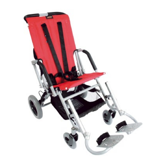
Design and Function Intended Use The Lightning push chair is intended for use as a pediatric mobility base. Designed to be highly durable while remaining portable and convenient, the Lightning is lightweight and easily folded, transported, and stored. Crafted with 7000 series aluminum, commonly used for aircraft structural members because of its excellent strength-to-weight properties, the Lightning is available in two models, three sizes, and two colors. -
Page 11: Features Of All Lightning Models
Design and Function Features of all Lightning Models Both the Lightning Standard and Lightning Special Edition models come in three sizes (11”, 14”, and 16”) and two color options, Red Glow or Navy Blue. 11” Lightning Standard: • Frame weighs only 25lbs. -
Page 12: Special Edition Features
Design and Function Special Edition Features The Lightning Special Edition model features all of the options of the Lightning Standard model, plus additional add-ons, including:... -
Page 13: Specifications For All Models
Design and Function Specifications for all Models 11” Model 14” Model 16” Model Overall Height (Push Handle) 36” 36” 38” Overall Width 19.5” 24” 25” Seat Angle Settings 30° 30° 30° Seat Depth 10-12” 12-14” 16-18” Seat to Floor 20” 21”... -
Page 14: Installation Instructions
Installation Instructions... -
Page 15: Preparation
Incorrect installation of the Lightning push chair or its accessories may cause damage to the hardware and/or injury to the user. Tools Use the proper tools to install and adjust the Lightning push chair to the desired position for the user. Ensure all torque specifications are followed. CAUTION The use of improper tools may cause damage to the device. -
Page 16: Required Tools
Installation Instructions Required Tools Below are the tools needed to complete the installation of the laterals: Tool: Adjustable or 10mm Crescent Wrench #1 Phillips Screwdriver 3/16” Hex Key (Note: Tools are not provided.) -
Page 17: Folding And Carrying The Lightning
Installation Instructions Folding and Carrying the Lightning Step One: Grasp the push chair handle(s). Use your foot to depress the folding lock mechanism, and continue to depress the mechanism while pushing the back of the push chair toward its seat. - Page 18 Installation Instructions Step Three: Unlatch the hook-and-loop strap from the back of the chair. Loop the strap under then back over the chair’s armrest, then fasten the hook-and-loop strap to the back of the chair.
- Page 19 Installation Instructions Step Four: Having secured the hook-and-loop strap around the armrest, lift the push chair by its plastic carrying handle.
-
Page 20: Adjusting The Seat Back Angle
Installation Instructions Adjusting the Seat Back Angle In order to adjust the back angle, the chair’s back upholstery must first be removed. Step One: Unlatch both hook-and-loop straps on the seat back. - Page 21 Installation Instructions Step Two: Remove the accessory tubes from both sides of the back. Accessory Tubes Step Three: Remove the back upholstery from the chair.
- Page 22 Installation Instructions Step Four: Using an adjustable or 10mm crescent wrench, remove both adjustment nuts from either side of the chair. Adjustment The seat back can be set to the following angles: 95° 90° 85°...
- Page 23 Installation Instructions Step Five: Move each side of the seat back to the desired angle, then replace and tighten both adjustment nuts.
-
Page 24: Installing The Foot Plates
Installation Instructions Installing the Foot Plates Step One: On each side of the push chair, locate the locking pin, pictured below. Locking Step Two: Insert each foot plate rod into the grooved receiver tracks on each side of the chair. - Page 25 Installation Instructions Step Three: Adjust each foot plate to the desired height. When in the desired location, secure each foot plate by inserting the locking pin into the corresponding hole on the receiver track.
-
Page 26: Foot Plate Depth Adjustment
Installation Instructions Foot Plate Depth Adjustment Step One: Swing each foot plate out, away from the chair. - Page 27 Installation Instructions Step Two: On each foot plate, use an adjustable or 10mm crescent wrench to loosen the two depth adjustment nuts, pictured below. Loosen to adjust depth. Step Three: Having loosened the depth adjustment nuts, slide each foot plate along its tracks to its desired position.
- Page 28 Installation Instructions Step Four: When each foot plate is in its desired position, secure it in place by tightening the depth adjustment nuts. Tighten to secure.
-
Page 29: Using And Adjusting The Safety Harness
Installation Instructions Using and Adjusting the Safety Harness Step One: Adjust the groin strap to the length desired, then firmly cinch down the strap to secure it. Step Two: Remove both hand screws from the seat back. Hand Screws... - Page 30 Installation Instructions Step Three: On the front of the chair, remove the top strap pins and re-insert them in the desired locations. When the strap pins have been inserted in their desired locations, replace and firmly tighten both hand nuts. To lock and unlock the safety harness: Insert both harness Lock:...
-
Page 31: Engaging And Disengaging The Wheel Lock
Installation Instructions Engaging and Disengaging the Wheel Lock 9.1.0 Step One: To engage the wheel lock, press down on the brake lever with your foot. This will lock both rear wheels. Brake Lever Step Two: To disengage the wheel lock, place your foot under the brake lever and, using your foot, pull the lever upwards. -
Page 32: Installing The Headrest Extension
Installation Instructions Installing the Headrest Extension 9.1.1 Step One: Insert both headrest extension rods into the accessory tubes on the seat back. Installing the Canopy Extension 9.1.2 Step One: Insert both canopy extension rods into the accessory tubes on the seat back. If the headrest extension is already in place, insert the canopy extension rods into the tubes on top of the headrest extension. -
Page 33: Installing The Padded Headrest
Installation Instructions Installing the Padded Headrest 9.1.3 Step One: Slide the padded headrest over the headrest extension, as pictured below. Step Two: On both the left and right side, thread the lower cord of each pair of cords through the top eyelet of the headrest extension. Then, firmly tie the cords of each pair to one another. - Page 34 Installation Instructions Step Three: Having tied the padded headrest to the headrest extension, tighten and fasten both hook-and-loop straps.
-
Page 35: Installing The Ankle Cuffs
Installation Instructions Installing the Ankle Cuffs 9.1.4 Step One: On each foot plate, use an adjustable or 10mm crescent wrench to loosen and remove the depth adjustment nuts. Then, remove each foot plate from its foot plate arm. Loosen and remove depth adjustment nuts to remove foot plate. - Page 36 Installation Instructions Step Three: On each foot plate’s underside, fasten the provided nuts to each ankle cuff screw. Use a #1 Phillips head screwdriver to tighten and secure each screw.
-
Page 37: Installing The Padded Harness Cover
Installation Instructions Step Four: Having secured the ankle cuffs to both foot plates, replace each foot plate on its foot plate arm and tighten its depth adjustment nuts. Installing the Padded Harness Cover 9.1.5 Step One: Wrap each padded harness cover around the top straps of the safety harness, then fasten the covers’... -
Page 38: Installing The Trunk Support Accessory
Installation Instructions Installing the Trunk Support Accessory 9.1.6 Step One: Place the trunk support accessory on the front of the seat back and fasten it around the back using the two rear hook-and-loop straps. - Page 39 Installation Instructions Step Two: On each side of the chair, wrap the strap connected to the innermost flap around the lower portion of the armrest tube, then fasten it to the flap’s hook-and-loop patch. Innermost Flap...
- Page 40 Installation Instructions Step Three: On each side of the chair, feed the strap connected to the outermost flap of the trunk support accessory through the available strap buckle, pulling the strap tight before fastening it to the outermost flap’s hook-and-loop patch. Outermost Flap Strap...
- Page 41 Installation Instructions Step Four: Take the remaining, unattached strap and feed it through the strap buckle on the opposite side of the chair, then cinch it back toward itself and fasten it to its hook-and-loop strap.
-
Page 42: Attaching The Work 'N Play Tray
Installation Instructions Attaching the Work ‘N Play Tray 9.1.7 Step One: Place the tray on top of the chair’s armrest handles. Step Two: Insert the locking pins into the armrests on both sides of the chair, as pictured below. Locking Remove both locking pins to detach the tray. -
Page 43: Transportation
- Shopping Basket - Rain Hood CAUTION The following instructions must be followed when using the Lightning as a vehicle seat. WARNING Failure to attach the hardware as detailed could lead to serious injury or death. Tools and Components Needed 10.2... -
Page 44: Assembly Instructions
Transportation 10.0 Assembly Instructions 10.2 Step One: Separate the four through clamps from the handle-threaded clamp by removing the four screws. Step Two: Loosely position the handle-threaded clamp and the through clamps to the front left and right bars, as pictured below. Step Three: Loosely position the handle-threaded clamp and the through clamps to the rear left and right bars, as pictured below. -
Page 45: Attaching The Lightning To A Vehicle
Attaching the Lightning to a Vehicle 10.3 Step One: Position the assembly in the vehicle over the floor track. The front of the Lightning should face the front of the vehicle (i.e., in the direction of travel). Step Two: Apply the chair’s brakes. Step Three: Attach the front restraints to the floor tracks and the front handle-threaded clamps, making sure they are in line with the floor tracks. -
Page 46: Wheel Replacement
Wheel Replacement 11.0 Replacing Wheels 11.1 In order to replace both front and back wheels, perform the following steps: Step One: From the outside of the wheel/wheel caster, insert the shoulder bolt through the wheel to the inside wheel caster/mount. Step Two: Place the washer and nut on the bolt from the inside, then use an adjustable or 10mm crescent wrench to tighten the bolt and secure the wheel. -
Page 47: First-Time Use
12.2 It is important that the customer be fully aware of the installation of the Lightning push chair, including how to use it and how it can be adjusted to fit the client comfortably. As a dealer, proceed as follows: •... -
Page 48: Cleaning And Maintenance
13.0 Cleaning and Maintenance Cleaning and Maintenance 13.1 Frame: • Wipe with a damp cloth and dry thoroughly on a daily basis. Never put away wet. • For stains, wipe with a damp cloth and warm, soapy (mild soap) water. •... -
Page 49: Notes
Notes 14.0... - Page 50 Notes 14.0...
- Page 51 Notes 14.0...
- Page 52 Stealth Products, LLC. • info@stealthproducts.com • www.stealthproducts.com +1(800) 965-9229 | +1(512) 715-9995 | 104 John Kelly Drive, Burnet TX 78611 Revision Date 2019-03-21 P91D420 Lightning Owner's Manual...
Need help?
Do you have a question about the Lightning and is the answer not in the manual?
Questions and answers