
Related Manuals for Roper Whitney 10M14-H


Summary of Contents for Roper Whitney 10M14-H
- Page 1 ROPER WHITNEY of ROCKFORD, Inc. 10M14-H 10 FOOT 14 Ga SHEAR OPERATIONS MANUAL ROPER WHITNEY of ROCKFORD, Inc. 2833 Huffman Blvd. Rockford, IL 61103 PHONE: (815) 962-3011 FAX: (815) 962-2227 LAST MODIFIED DEC, 2004...
-
Page 2: Table Of Contents
TABLE OF CONTENTS TOPIC PAGE 10M14 Mechanical Shear ............1 Specifications . -
Page 3: 10M14 Mechanical Shear
"always on" running motor. The 10M14-H shear runs very quiet as a result of this motor actuation system. The shear blades are two edged, and upper and lower blades are interchangeable. The shear comes standard with a manual style backgauge that is offered either as a front or rear operated type gauging system. -
Page 4: Specifications
208/230/460 VAC, 3 PHASE, 60 HZ 8. Approximate weight 5500 lb. * Roper Whitney of Rockford, Inc. recommends the use of high carbon/high chrome blades for shearing stainless steel in production quantities. Note, that these high carbon/high chrome blades are standard on all 10M14 shears. - Page 6 ROPER WHITNEY of ROCKFORD, INC. SAFETY RULES --- 10M14-H SHEAR 1. WARNING: Electrical Danger -- Misuse or improper installation of machinery connected to a source of electricity may result in accidental shock that could cause injury or death. Installation must conform to National Electric Code (Article 250 - Grounding, etc.) Electrical connections must be made by a trained and qualified electrician.
- Page 7 11. Use safety glasses and required protective tools. 12. Keep work areas clean and in proper order. 13. Be alert to all potential hazards.
- Page 8 Report any loss or damage to the delivering carrier promptly to insure proper handling of your claim. Also contact your Roper Whitney of Rockford Dealer. Prior to uncrating your 10M14-H shear, read the instructions to remove and lift the shear. Note the "red" instruction tag attached to the lifting eye.
-
Page 9: Electrical Connections
The ram gib-guide bearings are made from bearing bronze, and have grease-pockets packed with bearing grease at the Factory. These are long-life bearings; however, if a problem occurs consult the Roper Whitney of Rockford, Service Department. The motor gear-box is grease packed and requires no maintenance. -
Page 10: Operating Instructions
OPERATING INSTRUCTIONS WARNING -- Never operate, install blades, or perform maintenance work on your shear without proper supervision, instruction and without first reading and understanding the Operating Instructions in this manual. NEVER OPERATE SHEAR WITH LIFTING EYE INSTALLED! REMOVE THE LIFTING EYE BEFORE OPERATING SHEAR! This shear has been inspected and tested at the factory to cut full length stock of capacity gauge. - Page 11 PLEASE READ THE FOLLOWING!! WARNING: The 10M14-H shear is designed as a single action shear, and each stroke requires a repeat foot switch actuation. Once the foot switch has been tripped, the shear will make one complete stroke unless the stop button is pushed during the stroke.
-
Page 12: Blade Repositioning/Replacement
BLADE REPOSITIONING/REPLACEMENT PROCEDURE The upper and lower blades are two edge blades that can be rotated 180° to provide a new cutting edge. Either when rotating blades or replacing them after regrinding, a procedure is applicable: 1. Refer to Figure 2. 2. - Page 14 Figure 2...
-
Page 15: Blade Clearance Adjustment
BLADE CLEARANCE ADJUSTMENT PROCEDURE Blade adjustment is factory set to handle rated capacity materials and other various materials of varying thickness. When a blade is replaced, repositioned or resharpened, though, the cutting clearance needs to be checked and adjusted to make sure that the blades do not interfere, and/or an acceptable sheared-edge is obtained. - Page 16 BLADE CLEARANCE ADJUSTMENT PROCEDURE, cont. The blade adjustment is made with the ram adjustment screws as follows -- refer to Figure 3a. 1. Warning: Always set a larger clearance prior to running ram downward after the blades have been replaced, repositioned or re-sharpened. They must not hit! And holddown must be installed while performing the adjustment procedure.
- Page 17 Figure 3a ADJUSTMENT NUT Figure 3b...
-
Page 18: Front Arms
SIDE EXTENSION SQUARING GAUGES Part No. 273940042 The side extension squaring gauges are in 4-foot sections that can be assembled, with multiples, in 8 or 12 foot total gauge lengths. For most applications the four-foot section will be adequate. The four-foot sections are packaged in kit form with applicable scales for dimensional extension. -
Page 19: Light Beam Assembly
LIGHT BEAM ASSEMBLY Part No. 273940005 The light beam assembly fits onto the legs and is held with 1/4-20 screws. Electrical connections are made through the control box wall, and connected to terminal strip as shown in Figure 4. WARNING: The electrical connections must be properly grounded by the Green wire, and the 24 volt AC black and white wires must be appropriately connected to the box per Figure 4. - Page 20 DRO BACKGAUGE PERFORMANCE SPECS Power feed backgauge for quick in and out positioning. Final position is set with hand wheel. Large .71" LED display pre-programmed at factory. 24” (in) backgauge travel. Forward (IN) and reverse (OUT) over-travel switches to prevent backgauge crash.
-
Page 21: Using The Dro Backgauge
USING THE DRO BACKGAUGE 1. To operate the backgauge: a. Press and hold the “IN” button located on the control box to move backgauge in. b. Press and hold the “OUT” button located on the control box to move backgauge out. NOTE: FORWARD AND REVERSE OVER-TRAVEL SWITCHES ARE INSTALLED TO PREVENT BACKGAUGE CRASHES. - Page 22 3. To adjust the Scale Factor or Calibration (CAL): The Calibration, “CAL”, has been preset at the factory to obtain optimum accuracy. However, due to physical variances some adjusting may be necessary once the machine is set-up for use. Pressing & Holding the “PGM” push button in for several seconds will change the display from Position value to "CAL".
- Page 23 NC GAUGE PERFORMANCE SPECS 5 user-programmable preset moves Large 6-digit LED display set at factory to read in inches. Metric display is possible. High speed of 88 IPM and slow speed of 21.5 IPM 24” (in) backgauge travel Positioning either automatically or manually Forward (IN) and reverse (OUT) over-travel switches to prevent backgauge crash.
-
Page 24: Programming The Nc
PROGRAMMING THE NC BACKGAUGE There are 5 Programmable Presets which are buttons 1-5. To set the #1 Preset: 1. Push the "1" button. 2. Push the "ENTER" button. The display shows the current value. 3. Key in desired position. 4. Push "ENTER" button again to store value. If the number falls out of the pre-programmed range then the number will flash on the screen. -
Page 25: Using The Nc
USING THE NC BACKGAUGE There are 5 programmable presets and also jog controls both "in" and "out" in either slow or fast speeds. To jog the backgauge: 1. Push the "0" or "POSITION" button to verify that the current position is being displayed. 2. - Page 26 USING THE NC BACKGAUGE , cont To move to the #1 Preset: 1. Push the "1" button. 2. Display shows what is programmed into "1". 3. Push the "START"/"STOP" button to start movement. 4. Backgauge will move to desired position. 5.
- Page 27 INTERNAL DURANT PARAMETERS NOTE: All parameters for the DURANT have been factory programmed and should not need changing or adjusting. Please call factory if changes are necessary. EXTRACTING FUNCTION CODES FROM DURANT CONTROLLER 1. Hit FUNCTION ENTER. Note that all four (4) LED's are flashing. 2.
- Page 28 CHANGING FUNCTION CODES IN DURANT CONTROLLER 1. Hit FUNCTION ENTER. Note that all four (4) LED's are flashing. 2a. Hit FUNCTION (FUNCTION CODE) ENTER. Note that all four (4) LED's are still flashing. If they are not, a password lock has been entered. The password can be displayed by pressing and holding in FUNCTION and 0 when power is first turned on.
- Page 29 TO CHANGE CURRENT DISPLAYED POSITION Since there is no “home” or “zero” position, we use the following procedure to tell the backgauge where it is and it begins to count from that position. 1. Hit FUNCTION ENTER. Note that all four (4) LED's are flashing. 2.
-
Page 30: Appendix
APPENDIX 10M14-H PHYSICAL DIMENSIONS FIGURE 1... -
Page 31: Operator's Controls
OPERATOR’S CONTROL PANEL FIGURE 2 MODE OF OPERATION SWITCH: 1. CONTINUOUS 2. SINGLE or 3. JOG PULL: TURN ON MACHINE (ILLUMINATED RED WHEN ON) PUSH: TURN OFF MACHINE PUSH: EMERGENCY STOP 3-PHASE ELECTRICAL POWER DISCONNECT SWITCH... -
Page 32: 230V Std Electrical Wiring Diagram
230V STD ELECTRICAL WIRING DIAGRAM FIGURE 3A... -
Page 33: 230V Std Electrical Panel Layout
230V STD ELECTRICAL PANEL LAYOUT FIGURE 3B... -
Page 34: 230V Dro Electrical Wiring Diagram
230V DRO ELECTRICAL WIRING DIAGRAM FIGURE 4A... -
Page 35: 230V Dro Electrical Panel Layout
230V DRO ELECTRICAL PANEL LAYOUT FIGURE 4B... - Page 37 6M14 / 10M14 AIR-OPERATED FRONT MATERIAL RETURN OPERATIONS MANUAL ver 1.0 10/9/00 R O P E R W H I T N E Y O F R O C K F O R D , I N C .
- Page 39 Table of Contents About This Manual Conventions Used in This Manual ................2 Attention Boxes Obtaining Assistance .
-
Page 40: About This Manual
Material and information contained in this manual is confidential, including all design details and specifications. Roper Whitney Of Rockford, Inc. reserves all rights in this regard. Page 1... -
Page 41: Conventions Used In This Manual
6M14 / 10M14 Air-Operated Front Material Return Conventions Used in This Manual To make this manual easier to read and use, a few special symbols, conventions, and terms are used. Attention Boxes Attention boxes are used to: alert you to hazards which could result in harm to you, others, or the equipment;... -
Page 42: Obtaining Assistance
Roper Whitney of Rockford, Inc. 2833 Huffman Boulevard, Rockford, IL 61103 PHONE: (815) 962-3011 FAX: (815) 962-2227 E-MAIL: info@roperwhitney.com N O T E It may be required that you obtain service or parts through an authorized Roper Whitney distributor. Page 3... -
Page 43: Safety Precautions
6M14 / 10M14 Air-Operated Front Material Return Safety Precautions: WARNING POTENTIAL FOR INJURY OR DEATH Inattention to proper safety, operation, and maintenance procedures could result in per s onal injury or death and damage to the equipment. Before using the system, carefully read and fully understand the safety precautions described in this chapter and the supplemental sources listed below. -
Page 44: Personal Safety
6M14 / 10M14 Air-Operated Front Material Return Personal Safety Ensure that you know how to do the work in a correct, safe manner. Know the hazards associated with the work and how to protect yourself. If you are in any way uncertain about your job and the safe way to perform the work, ask your supervisor for instructions. -
Page 45: Tool Safety
6M14 / 10M14 Air-Operated Front Material Return Tool Safety Use the proper tool and equipment for the task. Inspect tools before each use to ensure that they are in proper working condition. Maintain tools in their proper working condition. Keep tools in their proper storage place when not in use. Remove all hand tools such as wrenches, hammers, and diagnostic equipment from the machine immediately after each use. -
Page 46: Work Area Safety
6M14 / 10M14 Air-Operated Front Material Return Work Area Safety Keep the work area well lighted, clean, neat, and orderly. Oils, water, or debris on the floor can cause someone to slip and fall. Use only approved cleaning fluids. Deposit trash, refuse, debris, and other waste in the proper refuse container. -
Page 47: Machine Setup And Operation Safety
6M14 / 10M14 Air-Operated Front Material Return Machine Setup and Operation Safety Read, understand, and follow all machine-mounted warning and instruction plates and signs. Make sure safety guards, shields, barriers, covers, and protective devices are in place, connected, and functional before operating the system. -
Page 48: System Operations
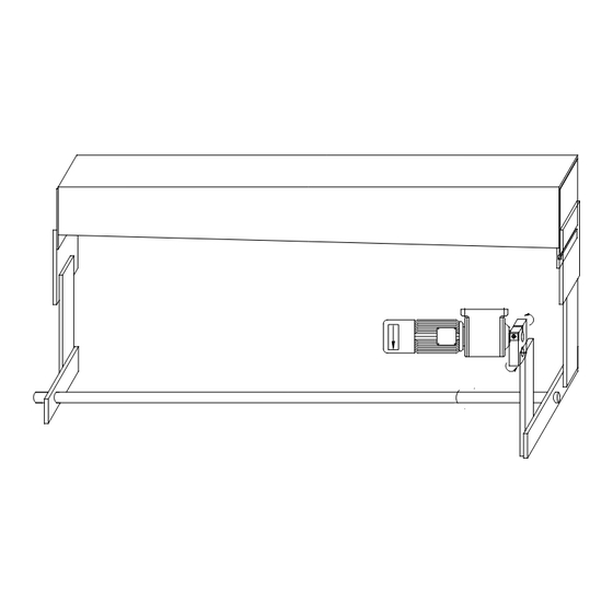
6M14 / 10M14 Air-Operated Front Material Return System Operations: The Air-Operated Front Material Return is an air actuated support table used in conjunction with the 6M14 / 10M14 electro-mechanical shear. The Air-Operated Front Material Return (or the Material Return) supports the work material during the shearing process, and then directs the cut piece into the material chute, located at the front of the machine. -
Page 49: System Description
6M14 / 10M14 Air-Operated Front Material Return System Description The Material Return system is comprised of the Material Return, two Support Arm assemblies, actuating Air Cylinder, mating air valving, and Control Switch. The Support Arms are mounted to the upper Ram, and are used to attach the pivots for the Material Return and Air Cylinder. - Page 50 6M14 / 10M14 Air-Operated Front Material Return The Air Cylinder attaches to the right-hand Support Arm through an adjustable mount. The rod of the Air Cylinder attaches to the Material Return through an actuation lever, attached to the rear of the Material Return.
- Page 51 6M14 / 10M14 Air-Operated Front Material Return The Air Cylinder is connected to an Air Valve that controls the rotation of the Material Return. The air pressure for the system is set by an air regulator. Incoming air is connected to system through a male connector attached to the air regulator.
-
Page 52: Operating Instructions
6M14 / 10M14 Air-Operated Front Material Return Operating Instructions The Air-Operated Front Material Return requires 80 to 100 psi clean filtered shop air. The system has an operating range of 60 to 100 psi, adjustable at the air regulator provided with the system. The incoming shop air is connected just below the regulator. - Page 53 6M14 / 10M14 Air-Operated Front Material Return Adjusting the Air Regulator varies the pressure with which the Material Return rotates. The pressure is preset at the factory to provide smooth quiet operation. If the air pressure requires adjusting, rotating the knob on the regulator clockwise will reduce the pressure, and rotating the knob counterclockwise will increase the pressure: observe the air pressure on the Pressure Gage.
-
Page 54: Control System
6M14 / 10M14 Air-Operated Front Material Return controls the upward speed. Rotating these valves clockwise reduces the speed of the Material Return. Each valve has a locking nut to prevent changes in the speed once the valves are set. CAUTION Excessive speed of the Material Return can cause vibration of the Return at its top position, and impacting (or banging) of the Material Return at its bottom position. - Page 55 6M14 / 10M14 Air-Operated Front Material Return Rotating the Selector Switch to "AUTO" prepares the Material Return to actuate each time the upper Ram is lowered to cut the work material. The Material Return remains in the horizontal position until a flag attached to the right hand side of the Ram activates the Actuation Proximity Switch (or the Prox Switch).
- Page 56 6M14 / 10M14 Air-Operated Front Material Return If the Prox Switch requires adjusting, the two (2) nuts threaded on to the switch can be rotated to move the switch in or out relative to the Actuation Flag. There is an LED light located at the rear of the Prox Switch that indicates the switch is activated when the light is on.
-
Page 57: Automatic Operation
6M14 / 10M14 Air-Operated Front Material Return Automatic Operation When the Selector Switch is set to "AUTO" the Material Return will raise and lower automatically as the Ram moves through its cutting cycle. The Air Cylinder holds the Material Return horizontally, allowing the work material to rest on it, until the Prox Switch is activated by the Actuation Flag. - Page 58 6M14 / 10M14 Air-Operated Front Material Return the legs of the machine together. This prevents damage to the Material Return. The "DOWN" mode is recommended for use in Continuous cycle cutting. It is also useful to create clearance between the Material Return and the Backgauge Stop.
-
Page 59: Periodic Maintenance
6M14 / 10M14 Air-Operated Front Material Return Periodic Maintenance The Air-Operated Material Return system requires very little maintenance. However, following these procedures will increase the life of the system, and help provide trouble-free operation. Although the system uses self-lubricated bearings, the pivot bearings for the Material Return should be inspected once a week (depending on use of the system) for signs of excessive wear. -
Page 60: Electrical Diagram
6M14 / 10M14 Air-Operated Front Material Return Electrical Diagram Page 21... -
Page 61: Air Circuit Diagram
6M14 / 10M14 Air-Operated Front Material Return Air Circuit Diagram Page 22... - Page 62 NOTES: 2833 Huffman Blvd., Rockford, Illinois 61103 Copyright, 1999, Roper Whitney of Rockford, Inc.,...
- Page 63 SHEAR MODEL: 10M14 PARTS MANUAL ROPER WHITNEY OF ROCKFORD 2833 HUFFMAN BLVD ROCKFORD, IL 61103 815-962-3011 www.roperwhitney.com...
- Page 64 10M14 SHEAR TABLE OF CONTENTS: SECTION 1.... BASIC MECHANICAL SECTION 2.... ELECTRICAL AND CONTROLS SECTION 3.... BACKGAUGE AND MATERIAL RETURN...
- Page 65 SECTION 1: BASIC MECHANICAL...
- Page 66 BASIC MECHANICAL - 10M14 FIG. 1...
- Page 67 Shear - Basic Mechanical 10M14 Table 1...
- Page 68 BASIC MECHANICAL - 10M14 FIG. 2...
- Page 69 Shear - Basic Mechanical 10M14 Table 2 RAM GUIDE...
- Page 70 BASIC MECHANICAL - 10M14 FIG. 3...
- Page 71 Shear - Basic Mechanical 10M14 Table 3 RAM AND LEG...
- Page 72 BASIC MECHANICAL - 10M14 VIEW A SEE VIEW A FIG. 4...
- Page 73 Shear - Basic Mechanical 10M14 Table 4 DRIVESHAFT...
- Page 74 BASIC MECHANICAL - 10M14 FIG. 5...
- Page 75 Shear - Basic Mechanical 10M14 Table 5 DRIVESHAFT...
- Page 76 BASIC MECHANICAL - 10M14 FIG. 6...
- Page 77 10M14 Shear - Basic Mechanical Table 6 BED SIDE ASSEMBLY...
- Page 78 BASIC MECHANICAL - 10M14 FIG. 7...
- Page 79 Shear - Basic Mechanical 10M14 Table 7 GUARDS...
- Page 80 BASIC MECHANICAL - 10M14 FIG. 8...
- Page 81 10M14 Shear - Basic Mechanical Table 8 FRONT AND SIDE EXTENSIONS 273940006 - 25" FRONT EXTENSION 273940042 - SIDE EXTENSION 16"-63" - " " 3 273940046 - OPTIONAL FLIP STOP FOR SIDE EXTENSION...
- Page 83 SECTION 2: ELECTRICAL AND CONTROLS...
- Page 84 ELECTRICAL AND CONTROLS - 10M14 FIG. 1...
- Page 85 Shear - Electrical and Controls 10M14 Table 1 FRONT OPERATED PANEL...
- Page 86 ELECTRICAL AND CONTROLS - 10M14 FIG. 2...
- Page 87 Shear - Electrical and Controls 10M14 Table 2 DRO PANEL...
- Page 88 ELECTRICAL AND CONTROLS - 10M14 FIG. 3...
- Page 89 Shear - Electrical and Controls 10M14 Table 3 NC PANEL...
- Page 90 ELECTRICAL AND CONTROLS - 10M14 FIG. 4...
- Page 91 Shear - Electrical and Controls 10M14 Table 4 LIGHT ASSEMBLY...
- Page 93 SECTION 3: BACKGAUGE MATERIAL RETURN...
- Page 94 BACKGAUGE AND RETURN - 10M14 FIG. 1...
- Page 95 Shear - Backgauge and Material Return 10M14 Table 1 FRONT OPERATED COUNTER...
- Page 96 BACKGAUGE AND RETURN - 10M14 FIG. 2...
- Page 97 Shear - Backgauge and Material Return 10M14 Table 2 FRONT OPERATED BACKGAUGE...
- Page 98 BACKGAUGE AND RETURN - 10M14 FIG. 3...
- Page 99 Shear - Backgauge and Material Return 10M14 Table 3 FRONT OPERATED BACKGAUGE ATTACHMENT...
- Page 100 BACKGAUGE AND RETURN - 10M14 FIG. 4...
- Page 101 Shear - Backgauge and Material Return 10M14 Table 4 DRO/NC BACKGAUGE...
- Page 102 BACKGAUGE AND RETURN - 10M14 FIG. 5...
- Page 103 Shear - Backgauge and Material Return 10M14 Table 5 DRO/NC BACKGAUGE ATTACHMENT...
- Page 104 BACKGAUGE AND RETURN - 10M14 FIG. 6...
- Page 105 10M14 Shear - Backgauge and Material Return Table 6 CHAINS RAM WITH HANDWHEEL ASSEMBLY " 9 " 0 RAM WITH NC/DRO ASSEMBLY " 7 " 0...
Need help?
Do you have a question about the 10M14-H and is the answer not in the manual?
Questions and answers