Table of Contents
Advertisement
ROPER WHITNEY
ROPER WHITNEY
of ROCKFORD, Inc.
of ROCKFORD, Inc.
10M14-G
10M14-G
10 FOOT 14 Ga SHEAR
10 FOOT 14 Ga SHEAR
OPERATIONS MANUAL
OPERATIONS MANUAL
ROPER WHITNEY of ROCKFORD, Inc.
2833 Huffman Blvd.
Rockford, IL 61103
(815) 962-3011
FAX: (815) 962-2227
www.roperwhitney.com
LAST MODIFIED JULY, 1997
Advertisement
Table of Contents

Related Manuals for Roper Whitney 10M14-G


Summary of Contents for Roper Whitney 10M14-G
- Page 1 ROCKFORD, Inc. 10M14-G 10M14-G 10 FOOT 14 Ga SHEAR 10 FOOT 14 Ga SHEAR OPERATIONS MANUAL OPERATIONS MANUAL ROPER WHITNEY of ROCKFORD, Inc. 2833 Huffman Blvd. Rockford, IL 61103 (815) 962-3011 FAX: (815) 962-2227 www.roperwhitney.com LAST MODIFIED JULY, 1997...
-
Page 2: Table Of Contents
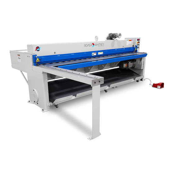
TABLE OF CONTENTS TOPIC PAGE 10M14 Mechanical Shear ............1 Specifications . - Page 3 "always on" running motor. The 10M14-G shear runs very quiet as a result of this motor actuation system. The shear blades are two edged, and upper and lower blades are interchangeable. The shear comes standard with a manual style backgauge that is offered either as a front or rear operated type gauging system.
-
Page 4: Specifications
208/230/460 VAC, 3 PHASE, 60 HZ 8. Approximate weight 5500 lb. * Roper Whitney of Rockford, Inc. recommends the use of high carbon/high chrome blades for shearing stainless steel in production quantities. Note, that these high carbon/high chrome blades are standard on all 10M14 shears. - Page 6 10M14-G PHYSICAL DIMENSIONS Figure 1...
- Page 7 OPERATOR'S CONTROL PANEL Figure 2 SINGLE MODE OF OPERATION: CONT CONTINUOUS, SINGLE, OR JOG ACTION SHEARING PULL: TURN ON MACHINE (ILLUMINATED RED WHEN ON) PUSH TO STOP PULL TO START PUSH: TURN OFF MACHINE PUSH: EMERGENCY STOP 3-PHASE ELECTRICAL POWER DISCONNECT SWITCH...
-
Page 8: Electrical Panel Layout
ELECTRICAL PANEL LAYOUT Figure 3a 230V H3H4 FU1, 2 AMP MICRON CONTROL TRANSFORMER #B150MBT713RK 208/230/460 VAC IN 24/120 VAC OUT FU2, 2 AMP 150VA X F X 1 120V SURGE SUPRESSOR G.E. BSLR2R SELECTOR SWITCH CONT CYCLE 1L1 3L2 1 3 N O SINGLE CYCLE JOG CYCLE G.E. - Page 9 ELECTRICAL WIRING DIAGRAM Figure 3b CUSTOMER SUPPLIED ROTATARY REMOTE MOUNT EQUIPMENT D I S C O N N E C T SAFETY SWITCH 230/3/60, AMP, NEMA FUSE, F U 1 F U 2 QTY (3) 2 AMP 2 AMP REMOTE MOUNT EQUIPMENT BRAKE COIL 5.O HP 13.6 AMPS...
-
Page 10: Electrical Connections
ROPER WHITNEY of ROCKFORD, INC. SAFETY RULES --- 10M14-G SHEAR 1. WARNING: Electrical Danger -- Misuse or improper installation of machinery connected to a source of electricity may result in accidental shock that could cause injury or death. Installation must conform to National Electric Code (Article 250 - Grounding, etc.) Electrical connections must be made by a trained and qualified electrician. - Page 11 10. Do not use machine if servicing is required. 11. Use safety glasses and required protective tools. 12. Keep work areas clean and in proper order. 13. Be alert to all potential hazards.
- Page 12 Report any loss or damage to the delivering carrier promptly to insure proper handling of your claim. Also contact your Roper Whitney of Rockford Dealer. Prior to uncrating your 10M14-G shear, read the instructions to remove and lift the shear. Note the "red" instruction tag attached to the lifting eye.
-
Page 13: Maintenance
The ram gib-guide bearings are made from bearing bronze, and have grease-pockets packed with bearing grease at the Factory. These are long-life bearings; however, if a problem occurs consult the Roper Whitney of Rockford, Service Department. The motor gear-box is grease packed and requires no maintenance. -
Page 14: Operating Instructions
OPERATING INSTRUCTIONS WARNING -- Never operate, install blades, or perform maintenance work on your shear without proper supervision, instruction and without first reading and understanding the Operating Instructions in this manual. NEVER OPERATE SHEAR WITH LIFTING EYE INSTALLED! REMOVE THE LIFTING EYE BEFORE OPERATING SHEAR! This shear has been inspected and tested at the factory to cut full length stock of capacity gauge. - Page 15 PLEASE READ THE FOLLOWING!! WARNING: The 10M14-G shear is designed as a single action shear, and each stroke requires a repeat foot switch actuation. Once the foot switch has been tripped, the shear will make one complete stroke unless the stop button is pushed during the stroke.
-
Page 16: Blade Repositioning/Replacement
BLADE REPOSITIONING/REPLACEMENT PROCEDURE The upper and lower blades are two edge blades that can be rotated 180° to provide a new cutting edge. Either when rotating blades or replacing them after regrinding, a procedure is applicable: 1. Refer to Figure 5. 2. -
Page 17: Blade Clearance Adjustment
Remove upper blade (item 7) and rotate forward 180°. With new cutting edge in position, replace all bolts (21 each, item 8), and work from center to the ends. Use a wood "pry-bar" to seat top of blade tight to ram blade seat. Tighten all bolts, working from center to the ends, very securely -- recommended tightening bolt torque of 40 ft/lb. - Page 18 ---- 1/2-20 X 1-3/4 BLADE BOLT 350700273 UPPER (RAM) BLADE 350700273 LOWER (BED) BLADE ---- 1/2-20 X 1-3/4 BLADE BOLT ---- HOLDDOWN ASSY ---- 5/16-18 X 2-1/2 SOC HD CAP SCREW ---- 3/4-10 HEX NUT ---- HOLDDOWN GUIDE BLOCK W/BUSHING ITEM QTY.
- Page 19 BLADE CLEARANCE ADJUSTMENT PROCEDURE Blade adjustment is factory set to handle rated capacity materials and other various materials of varying thickness. When a blade is replaced, re-positioned or re-sharpened, though, the cutting clearance needs to be checked and adjusted to make sure that the blades do not interfere, and/or an acceptable sheared-edge is obtained.
- Page 20 BLADE CLEARANCE ADJUSTMENT PROCEDURE, cont. The blade adjustment is made with the ram adjustment screws as follows -- refer to Figure 6a. 1. Warning: Always set a larger clearance prior to running ram downward after the blades have been replaced, repositioned or re-sharpened. They must not hit! And holddown must be installed while performing the adjustment procedure.
- Page 21 Figure 6a ADJUSTMENT NUT Figure 6b...
- Page 22 SIDE EXTENSION SQUARING GAUGES Part No. 273940042 The side extension squaring gauges are in 4-foot sections that can be assembled, with multiples, in 8 or 12 foot total gauge lengths. For most applications the four-foot section will be adequate. The four-foot sections are packaged in kit form with applicable scales for dimensional extension.
-
Page 23: Light Beam Assembly
LIGHT BEAM ASSEMBLY Part No. 273940005 The light beam assembly fits onto the legs and is held with 1/4-20 screws. Electrical connections are made through the control box wall, and connected to terminal strip as shown in Figure 7. WARNING: The electrical connections must be properly grounded by the Green wire, and the 24 volt AC black and white wires must be appropriately connected to the box per Figure7. - Page 24 REAR OPERATED-MANUAL BACKGAUGE INSTRUCTIONS Part No. 273940002 The backgauge, commonly called a parallel gauge, will travel 24 inches by rotating the handwheel on the right hand cast carrier that's located on the carrier rack-rods. Holding vertical knobs are used to lock the backgauge in position.
-
Page 25: Front Material Return
FRONT MATERIAL RETURN PART NO. 273940004 The front material return is an optional item that, when shipped as separate components, can be assembled to the shear according to the following procedure: 1. Refer to Figure 8. 2. Attach pusher bar assemblies (items 1 & 2) to pre-tapped holes in bottom of ram using (4) spacers (item 3), (4) 3/8-16 x 2-1/2 long socket head cap screws, (4) 3/8 dia. - Page 27 DRO BACKGAUGE PERFORMANCE SPECS Power feed backgauge for quick in and out positioning. Final position is set with hand wheel. Large 6-digit LED display set at factory to read in inches. Metric display is possible. 24” (in) backgauge travel. Forward (IN) and reverse (OUT) over-travel switches to prevent backgauge crash.
-
Page 28: Using The Dro
USING THE DRO BACKGAUGE 1. To operate the backgauge: Press and hold the “IN” button located on the control box to move backgauge in. Press and hold the “OUT” button located on the control box to move backgauge out. NOTE: FORWARD AND REVERSE OVER-TRAVEL SWITCHES ARE INSTALLED TO PREVENT BACKGAUGE CRASHES. - Page 29 NOTE: The parameter programming has been disabled by a jumper wire between the “PGM. DIS.” terminal (#11) and the “COMM.” terminal (#9), located at the rear of the Red Lion Gemini counter. NOTE: For convenience the terminal strip pulls away from the counter NOTE: The Scale Factor or “SF”...
- Page 30 DRO PROGRAMMING PARAMETERS NOTE: All parameters for the GEMINI 1000 have been factory programmed and should not need changing or adjusting. 1. To access a parameter, press the push buttons that correspond to the parameter number code. 2. On the left hand side of the display will be the number code that was selected, and on the right hand side will be the value for that parameter.
- Page 31 PRESET PARAMETER VALUES FOR DRO NUMBER PARAMETER PARAMETER FUNCTION CODE VALUE Sets unit to act as a counter Quadrature counting of encoder Double-edge counting Scale multiplier of 1 Decimal point position 000.000 Manual reset to zero Terminate at manual reset No right hand dummy zeros Enable use of reset.
- Page 32 NC GAUGE PERFORMANCE SPECS 5 user-programmable preset moves Large 6-digit LED display set at factory to read in inches. Metric display is possible. High speed of 88 ipm and slow speed of 21.5 ipm 24” (in) backgauge travel Positioning either automatically or manually Forward (IN) and reverse (OUT) over-travel switches to prevent backgauge crash.
-
Page 33: Programming The Nc
PROGRAMMING THE NC BACKGAUGE Durant POSITION MOVE DWELL MOVE HOME FUNCTION DWELL RECALL FAST JOG+ JOG- POSITION START ENTER STOP There are 5 Programmable Presets which are buttons 1-5. To set the #1 Preset: 1. Push the "1" button. 2. Push the "ENTER" button. The display shows the current value. 3. -
Page 34: Using The Nc
USING THE NC BACKGAUGE Durant POSITION MOVE DWELL MOVE HOME FUNCTION DWELL RECALL FAST JOG+ JOG- POSITION START ENTER STOP There are 5 programmable presets and also jog controls both "in" and "out" in either slow or fast speeds. To jog the backgauge: 1. - Page 35 USING THE NC BACKGAUGE Durant POSITION MOVE DWELL MOVE HOME FUNCTION DWELL RECALL FAST JOG+ JOG- POSITION START ENTER STOP To move to the #1 Preset: 1. Push the "1" button. 2. Display shows what is programmed into "1". 3. Push the "START"/"STOP" button to start movement. 4.
- Page 36 INTERNAL DURANT PARAMETERS EXTRACTING FUNCTION CODES FROM DURANT CONTROLLER 1. Hit FUNCTION ENTER. Note that all four (4) LED's are flashing. 2. Hit FUNCTION 5 ENTER. The display will show the current value for this function code. 3. Press ENTER. The next code number will display briefly and then its value will remain on screen.
- Page 37 SHEAR MODEL: 10M14 PARTS MANUAL ROPER WHITNEY OF ROCKFORD 2833 HUFFMAN BLVD ROCKFORD, IL 61103 815-962-3011 www.roperwhitney.com...
- Page 38 10M14 SHEAR TABLE OF CONTENTS: SECTION 1.... BASIC MECHANICAL SECTION 2.... ELECTRICAL AND CONTROLS SECTION 3.... BACKGAUGE AND MATERIAL RETURN...
- Page 39 SECTION 1: BASIC MECHANICAL...
- Page 40 BASIC MECHANICAL - 10M14 FIG. 1...
- Page 41 Shear - Basic Mechanical 10M14 Table 1...
- Page 42 BASIC MECHANICAL - 10M14 FIG. 2...
- Page 43 Shear - Basic Mechanical 10M14 Table 2 RAM GUIDE...
- Page 44 BASIC MECHANICAL - 10M14 FIG. 3...
- Page 45 Shear - Basic Mechanical 10M14 Table 3 RAM AND LEG...
- Page 46 BASIC MECHANICAL - 10M14 VIEW A SEE VIEW A FIG. 4...
- Page 47 Shear - Basic Mechanical 10M14 Table 4 DRIVESHAFT...
- Page 48 BASIC MECHANICAL - 10M14 FIG. 5...
- Page 49 Shear - Basic Mechanical 10M14 Table 5 DRIVESHAFT...
- Page 50 BASIC MECHANICAL - 10M14 FIG. 6...
- Page 51 10M14 Shear - Basic Mechanical Table 6 BED SIDE ASSEMBLY...
- Page 52 BASIC MECHANICAL - 10M14 FIG. 7...
- Page 53 Shear - Basic Mechanical 10M14 Table 7 GUARDS...
- Page 54 BASIC MECHANICAL - 10M14 FIG. 8...
- Page 55 10M14 Shear - Basic Mechanical Table 8 FRONT AND SIDE EXTENSIONS 273940006 - 25" FRONT EXTENSION 273940042 - SIDE EXTENSION 16"-63" - " " 3 273940046 - OPTIONAL FLIP STOP FOR SIDE EXTENSION...
- Page 56 SECTION 2: ELECTRICAL AND CONTROLS...
- Page 58 ELECTRICAL AND CONTROLS - 10M14 FIG. 1...
- Page 59 Shear - Electrical and Controls 10M14 Table 1 FRONT OPERATED PANEL...
- Page 60 ELECTRICAL AND CONTROLS - 10M14 FIG. 2...
- Page 61 Shear - Electrical and Controls 10M14 Table 2 DRO PANEL...
- Page 62 ELECTRICAL AND CONTROLS - 10M14 FIG. 3...
- Page 63 Shear - Electrical and Controls 10M14 Table 3 NC PANEL...
- Page 64 ELECTRICAL AND CONTROLS - 10M14 FIG. 4...
- Page 65 Shear - Electrical and Controls 10M14 Table 4 LIGHT ASSEMBLY...
- Page 66 SECTION 3: BACKGAUGE MATERIAL RETURN...
- Page 68 BACKGAUGE AND RETURN - 10M14 FIG. 1...
- Page 69 Shear - Backgauge and Material Return 10M14 Table 1 FRONT OPERATED COUNTER...
- Page 70 BACKGAUGE AND RETURN - 10M14 FIG. 2...
- Page 71 Shear - Backgauge and Material Return 10M14 Table 2 FRONT OPERATED BACKGAUGE...
- Page 72 BACKGAUGE AND RETURN - 10M14 FIG. 3...
- Page 73 Shear - Backgauge and Material Return 10M14 Table 3 FRONT OPERATED BACKGAUGE ATTACHMENT...
- Page 74 BACKGAUGE AND RETURN - 10M14 FIG. 4...
- Page 75 Shear - Backgauge and Material Return 10M14 Table 4 DRO/NC BACKGAUGE...
- Page 76 BACKGAUGE AND RETURN - 10M14 FIG. 5...
- Page 77 Shear - Backgauge and Material Return 10M14 Table 5 DRO/NC BACKGAUGE ATTACHMENT...
- Page 78 BACKGAUGE AND RETURN - 10M14 FIG. 6...
- Page 79 10M14 Shear - Backgauge and Material Return Table 6 CHAINS RAM WITH HANDWHEEL ASSEMBLY " 9 " 0 RAM WITH NC/DRO ASSEMBLY " 7 " 0...
- Page 80 BACKGAUGE AND RETURN - 10M14 14 22 FIG. 7...
- Page 81 Shear - Backgauge and Material Return 10M14 Table 7 MATERIAL RETURN...
- Page 82 BACKGAUGE AND RETURN - 10M14 FIG. 8...
- Page 83 10M14 Shear - Backgauge and Material Return Table 8 MATERIAL RETURN - EXPLODED VIEW...
- Page 84 BACKGAUGE AND RETURN - 10M14 FIG. 9...
- Page 85 Shear - Backgauge and Material Return 10M14 Table 9 MATERIAL RETURN ATTACHMENT...
Need help?
Do you have a question about the 10M14-G and is the answer not in the manual?
Questions and answers