Table of Contents
Advertisement
Quick Links
___________________________________________________________________________________________________
Instruction Manual
_________________________________________________________________________________________
Page 1 / 30
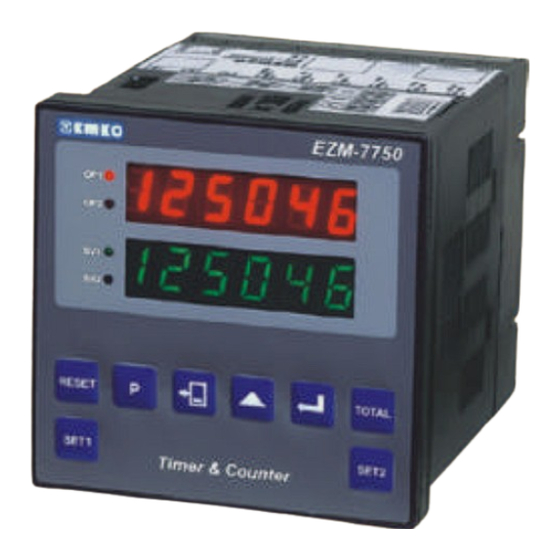
EZM-7750 72X72DIN 1/8
Multi-Functional Timer & Counter
•
6 digit actual, 6 digit set display
•
Operating with 2 sets
•
Reset, pause and ChA-ChB counter inputs
•
Selectable NPN/PNP input types
•
Programmable Counter/Totalizer Counter,
Batch Counter, Timer, Chronometer,
Frequencymeter and Tachometer
functions
•
Programmable time scale (Second,
Minute, Hour) for Timer and Chronometer
•
Operating with Automatic and Manual
Reset
•
For counting function, selectable INC,
DEC, INC/INC, INC/DEC, UP/DOWN,
•
x1 / x2 / x4 (with encoder) type of counting
•
Coefficient and decimal point position
•
Programmable alarm functions in
Frequencymeter and Tachometer modes.
•
Operating by absolute or offset in Counter
mode.
•
Optional serial communication with
MODBUS via RS-232 or RS-485
EZM7750_ENG_VER11
Advertisement
Table of Contents

Related Manuals for EMKO EZM-7750


Summary of Contents for EMKO EZM-7750
-
Page 1: Instruction Manual
___________________________________________________________________________________________________ EZM-7750 72X72DIN 1/8 Multi-Functional Timer & Counter • 6 digit actual, 6 digit set display • Operating with 2 sets • Reset, pause and ChA-ChB counter inputs • Selectable NPN/PNP input types • Programmable Counter/Totalizer Counter, Batch Counter, Timer, Chronometer,... -
Page 2: Table Of Contents
___________________________________________________________________________________________________ INSTRUCTION MANUAL ......................1 EU DECLARATION OF CONFORMITY..................... 3 1 INTRODUCTION:..........................5 1.1 MODEL CODE:..........................6 2 INSTALLATION:..........................7 2.1 GENERAL DESCRIPTION:......................7 2.2 DIMENSIONS:..........................8 2.3 PANEL CUT-OUT:........................8 2.4 ENVIRONMENTAL RATINGS:....................8 2.5 PANEL MOUNTING: ........................9 2.6 OPERATING FUNCTION SELECTION BY DIP SWITCHES: ...........10 3 ELECTRICAL CONNECTIONS: ....................11 3.1 TERMINAL LAYOUT AND CONNECTION INSTRUCTION:..........12... -
Page 3: Eu Declaration Of Conformity
___________________________________________________________________________________________________ EU DECLARATION OF CONFORMITY Manufacturer's Name EMKO ELEKTRONIK A.S. Manufacturer's Address : DOSAB, Karanfil Sk., No 6, 16369 Bursa, TURKEY The manufacturer hereby declares that the product: Product Name : Programmable Timer & Counter Unit Model Number : EZM-7750... - Page 4 ___________________________________________________________________________________________________ Please read the following information before using and thank you very much for buying Emko’ s product. The safety requirements are classified as either “warning“ and “caution” according to the following explanations: χ χ WARNING: Suggest that the user’ s mishandling can results in personal death or serious injury.
-
Page 5: Introduction
___________________________________________________________________________________________________ 1 INTRODUCTION: EZM series multifunctional counters can be used beside packing machines, production and quality control rollers, in cutting and processing machine of glass, plastic, marble, sheet iron, fabric all measuring and controlling of dimension, count, total count, speed, tachometer, productivity, time and can be adapted easily to all mechanical construction and automation systems. -
Page 6: Model Code
___________________________________________________________________________________________________ 1.1 MODEL CODE: BC D FG HI EZM-7750 (72x72 DIN 1/8) Supply Voltage 85-264VAC 50/60Hz 15 to 30VAC 50/60 Hz, 18 to 36VDC Customer Serial Interface RS-232 RS-485 (MODBUS) Output-1 Module-1 Relay Output Module SSR Drive Output Module 03 Transistor Output Module... -
Page 7: Installation
___________________________________________________________________________________________________ 2 INSTALLATION: χ χ WARNING: 1- A visual inspection of this product for possible damage occurred during shipment is recommended before installation. It is your responsibility to ensure that qualified mechanical and electrical technicians install this product. 2- If there is danger of serious accident resulting from a failure or defect in this unit, provide the unit with an appropriate external protective circuit to prevent an accident. -
Page 8: Dimensions
___________________________________________________________________________________________________ 2.2 Dimensions: 72mm / 2,83” 11.5/0.45" 76mm/2,99” 2.3 Panel Cut-Out: 97 mm/3,81in (min) 72 mm/2,83in (min) 2.4 Environmental Ratings: Operating Conditions: Operating temperature : -5 ... +55°C Maximum operating humidity : 90% Rh (non-condensing) Altitude : Up to 2000 m. χ... -
Page 9: Panel Mounting
___________________________________________________________________________________________________ 2.5 Panel Mounting: Insert To Panel: χ χ WARNING: During the equipment is putted in hole on the metal panel while mechanical installation some metal burrs can cause injury on hands, you should be careful. Installation parts of equipment should be tighten properly. The equipment can be drop from mounting place reason of vibration if installation parts leave soft. -
Page 10: Operating Function Selection By Dip Switches
___________________________________________________________________________________________________ Pulling Fixing Clamp: 1- You can unscrew to screws. 2- Pull the mounting clamp by screw driver from the front side of the device. 3- Pull the unit in the panel cut-out. 2.6 Operating Function Selection by DIP Switches: χ... -
Page 11: Electrical Connections
Totalizer Batch Counter Timer Tacho Chrono 85 to 264 Vac P/N : EZM-7750 Power Supply Module Output Terminal χ χ WARNING: Before the connecting of module terminals, you must ensure that correct I/O modules installed in the device. χ χ... -
Page 12: Terminal Layout And Connection Instruction
___________________________________________________________________________________________________ 3.1 Terminal Layout and Connection Instruction: 6mm / 0,23in Wire Size: 18AWG/1mm² Solid/Stranded 12 screw terminal M3 Option terminals Empty terminals 0,5Nm Holding screw 0,5Nm Screw driver 0,8x3mm 3.2 Power Supply: Switching power supply with multiple isolation High voltage version: 85 to 264 V~, frequency 50 / 60Hz. -
Page 13: Inputs
___________________________________________________________________________________________________ 3.3 Inputs: DIP SWITCH SETTING : PNP DIP SWITCH SETTING : NPN Proximity & switch connection Proximity & switch connection PROX. PROX. PROX. PROX. NOTE 1 NOTE 1 DIP SWITCH SETTING : PNP DIP SWITCH SETTING : NPN Incremental Encoder & switch connection Incremental Encoder &... -
Page 14: I/O Modules Installation
___________________________________________________________________________________________________ 3.4 I/O Modules Installation: First, detach all cable connections from the device and uninstall it from the panel Suppress to the lock pins where top and bottom of the device Pull the cover case by your hand through rear side Pull out the cover case from the device Slide input / output modules... - Page 15 ___________________________________________________________________________________________________ Module-1 / Module-2 Optional Output Modules EMO-710 EMO-720 EMO-700 SSR Driver Digital Output Relay Out. Module Output Module Module 5A@250Vac Module-1 Terminal Module-2 Terminal OUTPUT MODULES: Relay output connection Make sure the load does not exceed the rated capacity of the relay. Module-2 Fuse DC or AC...
- Page 16 ___________________________________________________________________________________________________ SSR driver output connection Module-2 Fuse Module-1 Fuse Digital Output Module Connection Module-2 Load Max. 40mA Without short circuit protection Module-1 Load Max. 40mA Without short circuit protection SERIAL INTERFACE MODULES: RS - 485 Serial Communication Interface RS - 232 Serial Communication Interface +5Vdc _________________________________________________________________________________________ Page 16 / 30...
-
Page 17: Operating Manual
___________________________________________________________________________________________________ Operating Manual 4 Front Panel Description: EZM-7750 Actual value and Parameter display SET1, SET2 and Parameter display RESET TOTAL SET1 SET2 Timer & Counter OP-1 (Output-1) condition watch by this LED as Actual values according to Parameter 14 and SV1 (Set-1) values. -
Page 18: Set-1 & Set-2 Adjustments
___________________________________________________________________________________________________ 4.1 Set-1 & Set-2 Adjustments: Observing and Changing to SET1 values SET1 Press button. The Set Value Display shows set value of SET1. When the cursor to become visible as flashing digit on the display, press button. You can change to SET1 value by button for the cursor digit position changing, button for the cursor digit value changing. -
Page 19: Parameters List
___________________________________________________________________________________________________ 4.3 Parameters List: COUNTER and TOTALIZER COUNTER PARAMETERS: Input type and function’s 0- UP Counting by a rising edge of Ch-A. 1- DOWN Counting by a falling edge of Ch-A. 2- UP Counting by a rising edge of Ch-A and DOWN Counting by a falling edge Ch-B. 3- UP Counting by a rising edge of Ch-A and Ch-B. - Page 20 ___________________________________________________________________________________________________ BATCH COUNTER PARAMETERS: Input type and function’s 0- UP Counting by a rising edge of Ch-A. 1- DOWN Counting by a falling edge of Ch-A. 2- UP Counting by a rising edge of Ch-A and DOWN Counting by a falling edge Ch-B. 3- UP Counting by a rising edge of Ch-A and Ch-B.
- Page 21 ___________________________________________________________________________________________________ TIMER PARAMETERS: This parameter time base for Timer and Counter Mode. 0- From 00 hour 00 minute to 99 housr 59 minutes 1- From 00 minute to 00 second 99 minutes 59 seconds 2- From 00 second 00 milisecond to 99 seconds 99 miliseconds PRO-05 3- From 00 hour 00 minute to 23 hours 59 minutes 4- From 000.00 hour to 999.99 hours...
- Page 22 ___________________________________________________________________________________________________ FREQUENCYMETER and TACHOMETER PARAMETERS: Configuration for measurement method. PRO-03 0- Counts per turn 1- Counts per time period. PRO-04 Contact Bounce for electrical noise. Adjustable from 0 to 250 miliseconds. This parameter is used when PRO-03=0 (counts per turn method). “Time-out” period can be set by PRO-07 this parameter (1 to 99 seconds).
- Page 23 ___________________________________________________________________________________________________ CHRONOMETER PARAMETERS: Chronometer function and signal inputs 0- Total period measurement (ChA input) PRO-02 1- Total pulse time measurement (ChA input) 2- Sum of the measured time period between the rising edges of ChA and ChB signals. PRO-04 Contact Bounce for electrical noise. Adjustable from 0 to 250 miliseconds. This parameter time base for Timer and Counter Mode.
-
Page 24: Output Functions
___________________________________________________________________________________________________ 4.4 Output Functions: Output function - 0 (Manual Reset) Counter, Totalizer Counter Output function - 2 (Manual Reset) Counter, Totalizer Counter Timer, Chronometer Timer, Chronometer Counting Direction : 0 --> P (Counting to upwards) Counting Direction : 0 --> P (Counting to upwards) Reset Reset Set2... - Page 25 ___________________________________________________________________________________________________ When the actual value reaches SET1 value, OUT1 becomes active. If OUT1was Counting Direction : P --> 0 (Counting to downwards) selected periodical, at the end of this time OUT1 changes position. If Out1 was selected indefinite, OUT1 changes position related to OUT2 or RESET input. Reset When the actual value reaches SET2 value, OUT2 becomes active and actual value resets.
- Page 26 ___________________________________________________________________________________________________ Counting Direction : P --> 0 (Counting to downwards) Counting Direction : P --> 0 (Counting to downwards) Reset Reset Set2 Set2 Set1 Set1 Out1 Out1 pulse time != 0 Out1 Out1 pulse time != 0 Out1 pulse time = 0 Out1 Out1 pulse time = 0 Out1...
- Page 27 ___________________________________________________________________________________________________ Output function - 7 Timer Chronometer Counting Direction : 0 --> P (Counting to upwards) Reset Set2 Set1 Out1 Out1 pulse time!=0 Out1 Out1 pulse time =0 Out2 pulse time = 0 or Out2 pulse time!=0 Out2 When the actual value is equal or bigger than the SET1 value, the OUT1 becomes active.
- Page 28 ___________________________________________________________________________________________________ Output function - 0 BATCH Counter Output function - 1 BATCH Counter Counting Direction : 0 --> P (Counting to upwards) Reset Ch-A SET2 COUNT-0 OP-2 SET1 BATCH-0 BATCH-0 Periodical OP-1 (Periodical) When the actual value reaches to “0” each time, Op2 becomes active during the period which is determined by Pro-17.
- Page 29 ___________________________________________________________________________________________________ Out1 Alarm output function Output Functions of Frequencymeter and Tachometer High Alarm Out1 output function (Non-Latching Output) Output-1(OUT1) Set1-Hys1 Set1 SV1-HYS1 Low Alarm Output-1(OUT1) Set1 Set1+Hys1 Out1 Deviation High Alarm Out2 output function (Non-Latching Output) Output-1(OUT1) SV2-HYS2 - Hys1 Set1+Set2 Set2 Deviation Low Alarm...
-
Page 30: Technical Specifications
___________________________________________________________________________________________________ TECHNICAL SPECIFICATIONS: TECHNICAL SPECIFICATIONS AND RATINGS Equipment use : Programmable Timer & Counter equipment Housing & Mounting : 72mm x 72mm x 86mm 1/8 DIN 43700 Plastic housing for panel mounting. Panel cut out is 69mm x 69mm. Protection : NEMA 4X (IP65 at front, IP20 at rear).
Need help?
Do you have a question about the EZM-7750 and is the answer not in the manual?
Questions and answers