Table of Contents
Advertisement
Quick Links
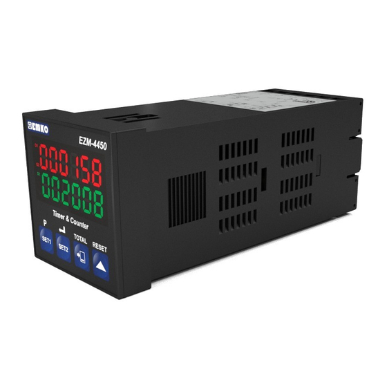
EZM-4450 48 x 48 1/16 DIN
Universal Input Programmable Timer &
Counter with Output Module System
- 6 digits Process (PV) and 6 digits Set (SV) Value Display
- Operation with 2 Set Value
- Reset , Pause and ChA-ChB Counting Inputs
- Configurable Counter / "Totalizer Counter", Batch Counter ,
Timer, Chronometer , Frequencymeter and Tachometer Functions
- Programmable Time Bases for Timer and Chronometer (Second ,
Minute , Hour )
- Operation with Automatic and Manual Reset
- Output Module System
- NPN/PNP Type Operation
- INC , DEC , INC / INC , INC / DEC , UP / DOWN , x1 / x2 / x4
Counting with Phase Shifting Property in Counter Function
- Multiplication Coefficient and Decimal Point Position
- Different Alarm Alternatives in Frequencymeter and Cycle
Measuring Functions
- Absolute or Offset Operation in Counter Function
- RS-232 (standard) or RS-485 (optional) Serial Communication
with Modbus ASCII or RTU Protocol
Instruction Manual. ENG EZM-4450 02 V14 07/14
Advertisement
Table of Contents

Related Manuals for EMKO EZM-4450


Summary of Contents for EMKO EZM-4450
- Page 1 - Multiplication Coefficient and Decimal Point Position - Different Alarm Alternatives in Frequencymeter and Cycle Measuring Functions - Absolute or Offset Operation in Counter Function - RS-232 (standard) or RS-485 (optional) Serial Communication with Modbus ASCII or RTU Protocol Instruction Manual. ENG EZM-4450 02 V14 07/14...
- Page 2 ABOUT INSTRUCTION MANUAL Instruction manual of EZM-4450 Programmable Timer&Counter consists of two main sections. Explanation of these sections are below. Also, there are other sections which include order information and technical specifications of the device. All titles and page numbers in instruction manual are in “CONTENTS”...
-
Page 3: Table Of Contents
3.4 COUNTING INPUT CONNECTION 3.4.1 PROXIMITY & SWITCH CONNECTION 3.4.2 INCREMENTAL ENCODER & SWITCH CONNECTION 3.4.3 SWITCH CONNECTION 3.5 GALVANIC ISOLATION TEST VALUES OF EZM-4450 PROGRAMMABLE TIMER&COUNTER AND OUTPUT MODULES 4.DEFINITIONS AND SPECIFICATIONS OF OUTPUT MODULES......Page 22 4.1 EMO-400 RELAY OUTPUT MODULE 4.2 EMO-410 SSR DRIVER MODULE... - Page 4 7.8.1 FREQUENCYMETER / TACHOMETER APPLICATIONS EXAMPLES 7.9 CHRONOMETER PARAMETERS 7.9.1 CHRONOMETER APPLICATIONS EXAMPLES 7.10 ACCESSING TO THE PROGRAM PARAMETERS 8.PROGRAM PARAMETERS..................Page 67 9.FAILURE MESSAGES IN EZM-4450 PROGRAMMABLE TIMER & COUNTER .. Page 100 10.SPECIFICATIONS....................Page 102 11.OTHER INFORMATION..................Page 103...
- Page 5 EU DECLARATION OF CONFORMITY Manufacturer’s Name : EMKO ELEKTRONIK A.S. Manufacturer’s Address : DOSAB, Karanfil Sk., No:6, 16369 Bursa, TURKEY The manufacturer hereby declares that the product: Product Name : Programmable Timer & Counter Type Number : EZM-4450 Product Category...
-
Page 6: General Specifications
Some application fields which they are used are below: Application Fields Glass Plastic Marble Sheet iron Automative Machine production industries 1.1 General Specifications Standard EZM-4450 Universal Supply Input 100-240 V , 50/60Hz Supply Voltage Low Voltage (optional) Input Supply Input 50/60Hz, 24V Relay, SSR Driver, Digital... -
Page 7: Ordering Information
1.2 Ordering Information All order information of EZM-4450 BC D FG HI M-4450 Programmable Timer&Counter are given on ( 48x48 1/16 DIN) the table at left. User may form appropriate device configuration from information and Supply Voltage codes that at the table and convert it to the 100-240V 15%;+10%... -
Page 8: Warranty
1.3 Warranty EMKO Elektronik warrants that the equipment delivered is free from defects in material and workmanship. This warranty is provided for a period of two years. The warranty period starts from the delivery date. This warranty is in force if duty and responsibilities which are determined in warranty document and instruction manual performs by the customer completely. -
Page 9: Installation
2.Installation Before beginning installation of this product, please read the instruction manual and warnings below carefully. In package , - One piece unit - Two piece mounting clamp - One piece instruction manual A visual inspection of this product for possible damage occured during shipment is recommended before installation. -
Page 10: General Description
Terminal protection cover Panel surface (maximum thickness 5mm / 0.2 inch) Front Panel IP65 protection 2.2 Dimensions Maximum 5mm / 0.2 inch EZM-4450 Timer & Counter TOTAL RESET SET1 SET2 48 mm / 1.89 inch 11.5 ± 1 mm /0.45 inch... -
Page 11: Panel Cut-Out
2.3 Panel Cut-Out 65 mm / 2.56 inch (min) 46 mm / 1.81 inch (min) -
Page 12: Environmental Ratings
2.4 Environmental Ratings Operating Conditions Operating Temperature : 0 to 50 °C Max. Operating Humidity : 90% Rh (non-condensing) Altitude : Up to 2000m. Forbidden Conditions: Corrosive atmosphere Explosive atmosphere Home applications (The unit is only for industrial applications) 2.5 Panel Mounting 1-Before mounting the device in your panel, make sure that the cut-out is of the right size. -
Page 13: Installation Fixing Clamp
2.6 Installation Fixing Clamp The unit is designed for panel mounting. 1-Insert the unit in the panel cut-out from the front side. 2-Insert the mounting clamp from the rear side of the unit and screw up the fixing screws until the unit completely immobile within the panel Montage of the unit to a system must be done with it’s own fixing clamps. -
Page 14: Selection Of Operation Function And Input Type With Dip Switch
2.8 Selection of Operation Function and Input Type with DIP Switch Operation function and input type ( NPN / PNP ) can be changed by DIP switch on the device. DIP Switch is under cover and cover is on top side of the device Function Selection Counter / Batch Counter... -
Page 15: Electrical Wirings
3.Electrical Wirings You must ensure that the device is correctly configured for your application. Incorrect configuration could result in damage to the process being controlled, and/or personal injury. It is your responsibility, as the installer, to ensure that the configuration is correct. Parameters of the device has factory default values. -
Page 16: Electrical Wiring Diagram
Electrical wiring of the device must be the same as ‘Electrical Wiring Diagram’ below to prevent damage to the process being controlled and personnel injury. Sensor Counting Inputs Supply Voltage P/N : EZM-4450 Communication Scocket MODULE-1 MODULE-2 Optional Output Module Terminals... -
Page 17: Connection Of Device Supply Voltage Input
3.3 Connection of Device Supply Voltage Input Connection of Universal Connection of Low Voltage Supply Voltage Input 24 V Supply Voltage Input Note-2 External Fuse External Fuse (24V : 1 A (1 A (24V : 1 A Power Power Supply Supply Switch Switch... -
Page 18: Counting Input Connection
3.4 Counting Input Connection 3.4.1 Proximity & Switch Connection DIP SWITCH ADJUSTMENT : PNP PROX. PROX. NOTE-2 NOTE-1 DIP SWITCH ADJUSTMENT : NPN PROX. PROX. NOTE-2 NOTE-1 NOTE-1 : Auxiliary power supply for external transmitter ± 10%, 50 mA maximum with short circuit protection NOTE-2 : Reset and Pause inputs have protection time against electrical contact debounce. -
Page 19: Incremental Encoder & Switch Connection
3.4.2 Incremental Encoder & Switch Connection DIP SWITCH ADJUSTMENT : PNP INCREMENTAL ENCODER 10 to 30V NOTE-2 NOTE-1 DIP SWITCH ADJUSTMENT : NPN INCREMENTAL ENCODER 10 to 30V NOTE-2 NOTE-1 NOTE-1 : Auxiliary power supply for external transmitter ± 10%, 50 mA maximum short circuit protection NOTE-2 : Reset and Pause inputs have protection time against electrical contact debounce. -
Page 20: Switch Connection
3.4.3 Switch Connection DIP SWITCH ADJUSTMENT : PNP NOTE-2 NOTE-1 DIP SWITCH ADJUSTMENT : NPN NOTE-2 NOTE-1 NOTE-1 : Auxiliary power supply for external transmitter ± 10%, 50 mA maximum short circuit protection NOTE-2 : Reset and Pause inputs have protection time against electrical contact debounce. -
Page 21: Emo-400 Relay Output Module
3.5 Galvanic Isolation Test Results of EZM-4450 Programmable Timer & Counter and Output Modules 2000V ( For EZM-4450.1...) 500V ( For EZM-4450.2...) Supply Input 2000V 2000V EMO-400 Relay Output Module 2000V 500V EMO-410 SSR Driver Module 2000V 500V EMO-420 Digital Output Module... -
Page 22: Definitions And Specifications Of Output Modules
4. Definitions and Specifications of Output Modules EZM-4450 programmable Timer &Counter is a modular product which is designed to operate with additional output units which user may need. Two output modules can be plugged in the device by the user. User may configure the product for different applications according to the system requirements with the output modules which are described in this section. -
Page 23: Ssr Driver Module
4.2 EMO-410 SSR Driver Module EMO-410 SSR Driver Module can be plugged in Module-1 or Module-2 socket to be used in applications that SSR driver output is necessary Specification of EMO-410 SSR Driver Module Output : Maximum 26 mA, 22V ±10%, isolated Dimensions : 14x30.7x41.4mm Applications of EMO-410 SSR Driver Module... -
Page 24: Installing And Pulling Out Output Modules
4.4 Installing and Pulling Out Output Modules First, detach all cable connections from the device and uninstall it from the panel. Suppress to the lock pins where top and bottom of the device Pull the cover case with your other hand from front panel to rear side. - Page 25 4.5 To Stick Output Modules’ Labels to the Equipment Every module which is plugged in Module-1 or Module-2 socket has labels’ for showing the relation between connection terminal and the device. These labels are attached to empty attachment places which are separated for Module-1 and Module-2 on the device. Labels for all modules and attachment places are shown below.
- Page 26 Example : If user installs EMO-400 Relay Output Module to Module-1 socket, EMO-410 SSR Output Module to Module-2 socket and attach the appropriate labels on the device view will be like below : Counter Chrono & Totalizer Batch Tacho Counter Timer Max.
-
Page 27: Connection Terminals Of Output Modules And Connection Wiring
5.Connection Terminals of Output Modules and Connection Wirings Module-1 / Module-2 Optional Output Modules EMO-410 EMO-420 EMO-400 SSR Driver Digital Output Relay Output Module Output Module Module Max. Max. 3A@250V 26mA, 22V 40mA@18V Module-1 Connection Terminals Module-2 Connection Terminals 5.1 EMO-400 Relay Output Module Connection Module-1 Module-2 T Fuse... -
Page 28: Digital (Transistor) Output Module Connection
5.3 EMO-420 Digital (Transistor) Output Module Connection Module-1 Module-2 Load Load 15-18 V 15-18 V Max.40mA Max.40mA... -
Page 29: Cable Connection Between Rs-232 Terminal Of The Device And Pc
6.Connection for RS-232 / RS-485 Serial Communication RS-232 Terminal Definitions RS-485 Terminal Definitions 6.1 Cable Connection Between RS-232 Terminal of the Device and the PC EZM-4450 PC (Personal Computer) 9 Pin DCON connection Cable Lenght must be max. 12 meters for 9600 baud rate... -
Page 30: Connection For Rs-485 Serial Communication
6.2 Connection for RS-485 Serial Communication PC (Personal Computer) RS-232 RS-485 Convertor RS-232 Connection MASTER Cable SLAVE-1 32 terminal can be connected in RS- 485 line Rt resistor = 120 For communication connection Twisted Pair cable must be used Cable lenght can be maximum 1000 meters in 9600 baud rate. -
Page 31: Installing Rs-232 / Rs-485 Serial Communication Modules To The Device
6.3 Installing RS-232 / RS-485 Serial Communication Modules to the Device Pull the cover case with your hand through rear side as explained in “Installing and Pulling Out Output Modules” section. Pull the modules in Module-1 and Module-2 socket through rear side. -
Page 32: Definition Of Front Panel And Accessing To The Parameters
7.Definition of Front Panel and Accessing to the Set Parameters 7.1 Definition of Front Panel EZM-4450 NOTE-1 Led indication of output is active (related to SET1) Displays Actual Value and Parameter Led indication of output is active (related to SET2) -
Page 33: Power On Observation Of Ezm - 4450 Programmable Timer & Counter And Software Revision On The Display
When power is applied to the device, software revision number of the controller is momentarily illuminated on actual value display. Then operation screen is observed. When power on, view of the screen is shown below: EZM-4450 Timer & Counter Revision number “ rEu” Revision... -
Page 34: Adjustment Of Set1 And Set2 Values
7.3 Adjustment of SET1 and SET2 Values Changing SET2 value in Counter / Totalizer Counter” functions “ Operation SET2 Screen Screen Timer & Counter Timer & Counter TOTAL RESET TOTAL RESET SET1 SET2 SET1 SET2 Press Shift button again. When shift button is pressed, 6th digit of SET2 value starts to flash. - Page 35 Changing SET1 value in Counter / “Totalizer Counter” function SET1 Screen Operation Screen Timer & Counter Timer & Counter TOTAL RESET TOTAL RESET SET1 SET2 SET1 SET2 Press Shift Button SET1 value is shown by pressing Press SET1 or SET2 SET1 button.
-
Page 36: Resetting Count Value And Observing Total Count Value In Counter / "Totalizer Counter" Function
7.4 Resetting Count Value and Observing Total Count Value in COUNTER / “TOTALIZER COUNTER” Function Operation Operation Screen Screen Press TOTAL button for 3 seconds, after Timer & Counter Timer & Counter count value becomes zero TOTAL RESET TOTAL RESET SET1 SET2 SET1... -
Page 37: Counter / "Totalizer Counter" Parameters
7.5 COUNTER / “TOTALIZER COUNTER” Parameters SET value for Output-1. Control of the Output-1 is done SET value for Output-1. Control of the Output-1 is done SET1 according to this value. It can be adjusted from according to this value. It can be adjusted from If SET1 operation form selection parameter is selected operation with offset... - Page 38 Automatic Reset-1. Count value is reset when it reaches to SET2 value (For 0 P ). Count value is added to total count value and device starts to count from Automatic Reset-2. Counting is stopped when count value reaches to SET2 value.Count value becomes zero (for 0 P ) at the end of output-2 pulse time And count value is added to total count value.
- Page 39 Point Position for display No point Between first and second digits Between second and third digits Between third and fourth digits Between fourth and fifth digits Saving Count Value (Power down back-up) Count value is saved to memory when power is off and restored on power up. Count value is not saved to memory when power is off Selection of SET1 Operation Form Operating without offset.
- Page 40 Stop Bit 1 Stop Bit 2 Stop Bits Reset and Set protection (Accessing from front panel) There is no Reset and Set protection Reset Button protection is active SET1 and SET2 protection is active Reset Button , SET1 and SET2 protection is active (Full protection) SET1 protection is active SET2 protection is active Multiplication Coefficient...
-
Page 41: Counter / "Totalizer Counter" Applications Examples
7.5.1 COUNTER / “TOTALIZER COUNTER” Applications Examples EXAMPLE-1 : There is a production band like in diagram below. Bottles are perceived by a proximity sensor in Ch-A. If Counting the bottles is done with upcount by using only Ch- Ch-A A input. - Page 42 EXAMPLE - 4 : There is a cutting unit below. 100- pulse encoder is connected to Ch-A and Ch-B inputs. Cutting Unit Ch-A Encoder with Ch-B 100 pulse parameter is , then device operates with offset. If SET1 is negative value, then Output-1 will be active in SET2-SET1.
-
Page 43: Batch Counter Parameters
7.6 BATCH COUNTER Parameters SET value for Output-1. Control of the Output-1 is done SET value for Output-1. Control of the Output-1 is done SET1 according to this value. It can be adjusted from according to this value. It can be adjusted from SET value for Output-2. - Page 44 Output Functions Manual Reset. BATCH counting operation continues until manual reset input is active. Automatic Reset.BATCH counting operation continues until Batch count value reaches to SET1 value.When Batch count value is equal to SET1 value,Batch count value becomes zero (for 0 P) and device starts to count again.
- Page 45 Selection of Modbus Protocol Type MODBUS ASCII communication protocol is selected. MODBUS RTU communication protocol is selected Parity No parity Odd parity Even parity Baud Rate 1200 Baud Rate 2400 Baud Rate 4800 Baud Rate 9600 Baud Rate 19200 Baud Rate Stop Bit 1 Stop Bit 2 Stop Bits...
-
Page 46: Batch Counter Applications Examples
7.6.1 BATCH COUNTER Applications Examples EXAMPLE-1 : There is a production band like in diagram below. Bottles are perceived by a proximity sensor in Ch-A. If Device is used in a packing line as shown on Ch-A the left. Bottles must be counted into packs of 4 bottles and dispatched in a box containing a batch of 4 packs. -
Page 47: Timer Parameters
7.7 TIMER Parameters SET value for Output-1. Control of the Output-1 is done SET1 according to this value. It can be changed by time unit and scale selection parameter SET value for Output-2. Control of the Output-2 is done SET2 according to this value. - Page 48 Automatic Reset-3. Count value becomes zero (0 P) when it reaches to SET2 value. Device starts to count again. Meanwhile, SET2 value is shown in actual value display, count value is shown at the end of output-2 pulse time Automatic Reset-4. Counting is continued when count value reaches to SET2 value.Count value is becomes zero (0 P) at the end of Output-2 pulse time .
- Page 49 Selection of Modbus Protocol Type MODBUS ASCII communication protocol is selected. MODBUS RTU communication protocol is selected Parity No parity Odd parity Even parity Baud Rate 1200 Baud Rate 2400 Baud Rate 4800 Baud Rate 9600 Baud Rate 19200 Baud Rate Stop Bit 1 Stop Bit 2 Stop Bits...
-
Page 50: Timer Applications Examples
Pause When switch is “Off”, counting is stopped. Time between Switch opening and closing of the switch is observed on actual EZM-4450 value screen. Expired time can be reset with manual reset. If total Timer & Counter operation time is wanted to be observed on the screen,... -
Page 51: Frequencymeter / Tachometer Parameters
7.8 FREQUENCYMETER / TACHOMETER Parameters SET value for Output-1. Control of the Output-1 is done SET value for Output-1. Control of the Output-1 is done SET1 according to this value. It can be adjusted from according to this value. It can be adjusted from SET value for Output-2. - Page 52 Output-2 Function Output-2 is latched. It does not change position until manual reset is applied. Non-latched with hysteresis output is selected. Alarm Functions for Output-1 If Output-1 function parameter , Output-1 becomes active according to this parameter High Alarm. Low Alarm. Deviation High Alarm.
- Page 53 Start of Controlling Controlling is started when the device is energised Controlling is started when count value reaches to SET1 value. Controlling is started when count value reaches to SET2 value. Point Position for display No point Between first and second digits Between second and third digits Between third and fourth digits Between fourth and fifth digits...
- Page 54 Reset and Set protection (Accessing from front panel) There is no Reset and Set protection Reset Button protection is active SET1 and SET2 protection is active Reset Button , SET1 and SET2 protection is active (Full protection) SET1 protection is active SET2 protection is active Frequency / Cycle Multiplication Coefficient Count value is multiplied with this value.
-
Page 55: Frequencymeter / Tachometer Applications Examples
7.8.1 FREQUENCYMETER / TACHOMETER Applications Examples Two different methods are used in Frequencymeter / Tachometer function; Method -1 : To get frequency or cycle value by measuring the revolution time (This method is used if the sensor sends one pulse per revolution) Method -2 : To get frequency or cycle value by counting the pulses during the time is set in parameter Method -1 :... - Page 56 Method -2 : parameter is Pulses in Ch-A input is counted during time is set in parameter. Average time for one pulse is calculated. EXAMPLE-2 : For one revolution of cylinder 10 pulse is applied in Ch-A input during Ch-A Ch-A 5 is shown on the 10 pulse per revolution...
-
Page 57: Chronometer Parameters
7.9 CHRONOMETER Parameters SET value for Output-1. Control of the Output-1 is done SET1 according to this value. It can be changed by time unit and scale selection parameter SET value for Output-2. Control of the Output-2 is done SET2 according to this value. - Page 58 Output Functions Manual Reset-1. Device continues to count till manual reset is applied. Output-2 pulse time is not considered. Manual Reset-2. Device continues to count till count value reaches to SET2 value. For starting to count again, manual reset input must be active. Output- 2 pulse time is not considered.
- Page 59 Saving Count Value (Power down back-up) Count value is saved to memory when power is disconnected and restored on power up. Count value is not saved to memory when power is disconnected Slave Address Device address for serial communication bus. It can be adjusted from Selection of Modbus Protocol Type MODBUS ASCII communication protocol is selected.
- Page 60 Ch-A When switch is “On”, counting is started (Minute / second). Switch When switch is “Off”, counting is stopped. Time between EZM-4450 opening and closing of the switch is observed on actual value screen. Timer & Counter Expired time can be reset with manual reset. If total...
-
Page 61: Accessing To The Program Parameters
7.10 Accessing to the Program Parameters Parameters are grouped as program parameters. Accessing to the program parameters is same for all functions. So, only accessing to the program parameters for COUNTER / “TOTALIZER COUNTER” is explained in this section. For details on parameters refer to PROGRAM PARAMETERS section. - Page 62 Output Functions The most significant digit of the parameter (1st digit for this parameter) flashes. Yo u c a n c h a n g e t h e p a r a m e t e r w i t h INCREMENT button, save it Timer &...
- Page 63 Output-2 Pulse Time The most significant digit of the parameter (4th digit for this parameter) flashes. You can change the p a r a m e t e r w i t h INCREMENT button, Timer & Counter save it to the memory and p a s s t o t h e n e x t TOTAL RESET...
- Page 64 SET1 Operation Form The most significant digit of Selection the parameter (1st digit for this parameter) flashes. You can change the p a r a m e t e r w i t h INCREMENT button, Timer & Counter save it to the memory and p a s s t o t h e n e x t TOTAL RESET...
- Page 65 Baud Rate The most significant digit of the parameter (1st digit for this parameter) flashes. You can change the p a r a m e t e r w i t h INCREMENT button, Timer & Counter save it to the memory and p a s s t o t h e n e x t TOTAL RESET...
- Page 66 Program Password When password screen is shown if ENTER User can change the button is pressed without p a r a m e t e r w i t h entering the password this INCREMENT button, parameter can not be save it to the memory and observed.
-
Page 67: Program Parameters
8. PARAMETRELER 8. Program Parameters Input Types and Functions (It is accessible in COUNTER / “TOTALIZER COUNTER” and BATCH COUNTER functions) Upcount on rising edge of Ch-A input Ch-A Pause Start Value on Value = 0 the Screen Downcount on rising edge of Ch-A input. Ch-A Pause Start... - Page 68 Upcount on rising edge of Ch-A input Upcount on rising edge of Ch-B input Ch-A Ch-B Start Counting to Value on Value = 0 upwards the Screen Start Counting to Value on Value = 8 downwards the Screen Upcount on rising edge of Ch-A input when Ch-B is at 0 Downcount on rising edge of Ch-A when Ch-B is at 1 Ch-A DOWN...
- Page 69 x2 Phase Shifting (for incremental encoders) Upcount on rising edge of Ch-A when Ch-B is at 0 Downcount on falling edge of Ch-A when Ch-Bis at 0 Downcount on rising edge of Ch-A when Ch-B is at 1 Upcount on falling edge of Ch-A when Ch-B is at 1 Ch-A Ch-B Start...
- Page 70 Selection of Input Type Function for Chronometer (It is accessible only in CHRONOMETER function) Period measurement in Ch-A input. Ch-A Value on the Screen T1+T2+T3 T1+T2 Pulse time measurement in Ch-A input. Ch-A Value on the Screen T1+T2+T3 T1+T2 Sum of the time difference between Ch-A and Ch-B inputs rising edges Ch-A Ch-B...
- Page 71 Selection of Measuring Method (It is accessible only in FREQUENCYMETER / TACHOMETER Function) Frequency or cycle is calculated by measuring cycle time of the signals in Ch-A input Frequency or cycle is calculated by counting the pulses in Ch-A input during the time is set in measurement period parameter For details on these methods, refer to Section 7.8.1“Examples About Frequencymeter/Tachometer Function Applications”...
- Page 72 Hour It can be adjusted from Minute It can be adjusted from Second It can be adjusted from After adjustment of Time Range parameter , if SET1 and SET2 values are not appropriate for this selection, SET1 and SET2 are changed according to this selection.(E.g.
- Page 73 How it operates in COUNTER / “TOTALIZER COUNTER”, TIMER and CHRONOMETER functions is explained below: Counting direction : P 0 (Downcount) Reset Set2 Set1 Output-1 Output-1 Output-2 When the count value reaches to SET1 value, Output-1 becomes active. If Output-1 Pulse Time , Output-1 does not change condition until manual reset input is active.
- Page 74 When the count value reaches to SET1 value, Output-1 becomes active. If Output-1 pulse time , Output-1 does not change position until manual reset input is active. If Output-1 pulse time is not 0, Output-1 becomes inactive at the end of the pulse time.
- Page 75 Manual Reset-3. Counting continues until Manual Reset input is active. (Output-2 Pulse Time is considered) How it operates in COUNTER / “TOTALIZER COUNTER”, TIMER and CHRONOMETER functions is explained below: Counting direction : 0 P (Upcount) Reset Set2 Set1 Output-1 Output-1 Output-2 Output-1...
- Page 76 How it operates in COUNTER / “TOTALIZER COUNTER”, TIMER and CHRONOMETER function is explained below: Counting direction : P 0 (Downcount) Reset Set2 Set1 Output-1 Output-1 Output-2 Output-1 Output-2 When the count value reaches to SET1 value, Output-1 becomes active. If Output-1 pulse time is not 0, Output-1 changes position at the end of the pulse time.If Output-1 Pulse Time...
- Page 77 Automatic Reset-1 How it operates in COUNTER / “TOTALIZER COUNTER”, TIMER and CHRONOMETER functions is explained below: Counting direction : 0 P (Upcount) Reset Set2 Set1 Output-1 Output-1 Output-2 Output-1 Output-2 When the count value reaches to SET1 value, Output-1 becomes active. If Output-1 pulse time is not 0, Output-1 changes position at the end of the pulse time.If Output-1 Pulse Time...
- Page 78 How it operates in COUNTER / “TOTALIZER COUNTER”, TIMER and CHRONOMETER function is explained below: Counting Direction : P 0 (Downcount) Reset Set2 Set1 Output Output Output Output Output When the count value reaches to SET1 value, Output-1 becomes active. If Output-1 pulse time is not 0, Output-1 changes position at the end of the pulse time.If Output-1 Pulse Time...
- Page 79 Automatic Reset-2 How it operates in COUNTER / “TOTALIZER COUNTER”, TIMER and CHRONOMETER function is explained below: Counting direction : 0 P (Upcount) Reset Set2 Set1 Output-1 Output-1 Output-2 Reset Set2 Set1 Output-1 Output-1 Output-2 When the count value reaches to SET1, Output-1 becomes active. If Output-1 pulse time is not 0, Output-1 changes position at the end of the pulse time.
- Page 80 How it operates in COUNTER / “TOTALIZER COUNTER”, TIMER and CHRONOMETER functions are explained below: Counting direction : P 0 (Downcount) Reset Set2 Set1 Output-1 Output-1 Output-2 Reset Set2 Set1 Output-1 Output-1 Output-2 When the count value reaches to SET1, Output-1 becomes active. If Output-1 pulse time is not 0, Output-1 changes position at the end of the pulse time.
- Page 81 Automatic Reset-3 How it operates in COUNTER / “TOTALIZER COUNTER”, TIMER and CHRONOMETER functions are explained below: Counting direction : 0 P (Upcount) Reset Set2 Set1 Output-1 Output-1 Output-2 Reset Set2 Set1 Output-1 Output-1 Output-2 When the count value reaches to SET1, Output-1 becomes active.If Output-1 pulse time is not 0, Output-1 changes position at the end of the pulse time.
- Page 82 How it operates in COUNTER / “TOTALIZER COUNTER”, TIMER and CHRONOMETER functions are explained below: Counting Direction : P 0 (Downcount) Reset Set2 Set1 Output-1 Output-1 Output-2 Reset Set2 Set1 Output-1 Output-1 Output-2 When the count value reaches to SET1, Output-1 becomes active. If Output-1 pulse time is not 0, Output-1 changes position at the end of the pulse time.
- Page 83 Automatic Reset-4 How it operates in COUNTER / “TOTALIZER COUNTER“, TIMER and CHRONOMETER functions are explained below: Counting direction : 0 P (Upcount) Reset Set2 Set1 Output-1 Output-1 Output-2 Reset Set2 Set1 Output-1 Output-1 Output-2 When the count value reaches to SET1, Output-1 becomes active. If Output-1 pulse time is not 0, Output-1 changes position at the end of the pulse time.
- Page 84 How it operates in COUNTER / “TOTALIZER COUNTER”, TIMER and CHRONOMETER functions are explained below: Counting Direction : P 0 (Downcount) Reset Set2 Set1 Output-1 Output-1 Output-2 Reset Set2 Set1 Output-1 Output-1 Output-2 When the count value reaches to SET1, Output-1 becomes active. If Output-1 pulse time is not 0, Output-1 changes position at the end of the pulse time.If Output-1 Pulse Time...
- Page 85 Automatic Reset-5 Pulse times is not considered. How it operates in COUNTER / “TOTALIZER COUNTER” functions are explained below: Counting direction : 0 P (Upcount) Reset Set2 Set1 Output-1 Output-2 If count value is equal or greater than SET1 value, then Output-1 becomes active.
- Page 86 Automatic Reset-5 Output-2 Pulse Time is not considered How it operates in TIMER and CHRONOMETER functions are explained below: Counting direction : 0 P (Upcount) Reset Set2 Set1 Output-1 Output-1 Output-2 If count value is equal to or greater than SET1 value, then Output-1 becomes active.
- Page 87 Output Functions for BATCH COUNTER Manual Reset How it operates in BATCH COUNTER function is explained below: Counting direction : 0 P (Upcount) Reset Ch-A SET2 Count Value Output-2 SET1 Batch Value Output-1 Output-1 When count value reaches to SET2 value, count value is reset and Output-2 becomes active.If Output-2 pulse time Then Output-2 does not change position until manual reset input is active.
- Page 88 How it operates in BATCH COUNTER function is explained below: Counting Direction : P 0 (Downcount) Reset Ch-A SET2 Count value Output-2 SET1 Batch value Output-1 Output-1 When count value reaches to , count value becomes equal to SET2 and Output-2 becomes active. If Output-2 Pulse Time , then Output-2 does not change position until manual reset input is active.
- Page 89 Automatic Reset How it operates in BATCH COUNTER function is explained below: Counting direction : 0 P (Upcount) Reset Ch-A SET2 Count value Output-2 SET1 Batch value Output-1 Output-1 When count value reaches to SET2 value, count value is reset and Output-2 becomes active.
- Page 90 Count direction : P 0 (Downcount) Reset Ch-A SET2 Count value Output-2 SET1 Batch value Output-1 Output-1 When count value reaches to value, count value becomes equal to SET2 value and Output-2 becomes active. If Output-2 pulse time , then Output-2 does not change position until manual reset input is active.
- Page 91 Time Out ( Input Signal Reset Time ) (It is accessible only in FREQUENCYMETER / TACHOMETER function) Actual count value is reset if no signal is applied to Ch-A input for a time which is greater than the value is set in this parameter. It can be adjusted from This parameter is visible if measurement method selection parameter...
- Page 92 Non-latched with hysteresis output is selected. Output-1 is non-latched SET1 SET1 - HYS1 Output-1 Output-1 is an alarm output. For details, refer to Alarm Functions for Output-1 parameter Only Ch-A input is performed in Frequencymeter/Tachometer functions Output-2 Function (It is accessible only in FREQUENCYMETER / TACHOMETER Function) Output is latched.
- Page 93 Non-latched with hysteresis output is selected. Output-2 is non-latched SET2 SET2 - HYS2 Output-2 Only Ch-A input is performed in Frequencymeter/Tachometer functions Alarm Functions for Output-1 (It is accessible only in FREQUENCYMETER / TACHOMETER Function) If Output-1 function parameter is selected alarm output, then Output-1 becomes active according to this parameter.
- Page 94 Deviation High Alarm. Output-1 - Hys1 Set1+Set2 Set2 Count Value Deviation Low Alarm. Output-1 Set2-Set1 + Hys1 Set2 Count Value Deviation Band Alarm. Output-1 - Hys1 Set2-Set1 Set1+Set2 + Hys1 Set2 Count Value Only Ch-A input performs in Frequencymeter / Tachometer function. Hysteresis for Output-1 (It is accessible in FREQUENCYMETER / TACHOMETER functions) It defines hysteresis for Output-1.
- Page 95 Hysteresis for Output-2 (It is visible only in FREQUENCYMETER / TACHOMETER Function) It defines hysteresis for Output-2. It is used if Output-2 is non-latched. It can be adjusted from Only Ch-A input performs in Frequencymeter / Tachometer function. Output-1 Operation Form Output-1 Normally non-energised Output-1 Normally energised Output-2 Operation Form...
- Page 96 Direction of Counting (It is accessible in functions except for FREQUENCYMETER/ TACHOMETER functions) Upcount. ( 0 Preset ) Downcount. ( Preset If Input Types and Functions parameter COUNTER / “TOTALIZER COUNTER” functions, then direction of counting parameter can not be accessed. Point Position for Display (It is accessible in functions except for TIMER and CHRONOMETER functions)
- Page 97 SET1 Operation Form Selection (It is accessible only in COUNTER / “TOTALIZER COUNTER” Function) Absolute operation.SET1 can be adjusted from Operation with offset. SET1 can be defined ± Offset according to SET2 value.( SET1 = SET1 + SET2 ) For example ;if operation with offset is selected, SET1 = 5000, SET2 = 10000.
- Page 98 Baud Rate 1200 Baud Rate 2400 Baud Rate 4800 Baud Rate 9600 Baud Rate 19200 Baud Rate Communication Stop Bit selection 1 Stop Bit 2 Stop Bits Reset and Set protection (For accessing from front panle) There is no Reset and Set protection Only RESET button protection is active.
- Page 99 ENTER button without entering password (for observing the parameters): User can see all parameters except Program Password but device does not allow to do any changes with parameters. ( Please refer to Section 9. Failure Messages in EZM-4450 Programmable Timer & Counter (2) )
-
Page 100: Failure Messages In Ezm-4450 Programmable Timer & Counter
9. Failure Messages in EZM-4450 Programmable Timer & Counter 1 - Position of the DIP Switch is wrong. (DIP Switch determines the operation function of the device and it is under the top cover) For details, refer to Section 2.8 “Selection of Operation Function and Input Type with DIP Switch”. - Page 101 Multiplication Coefficient For COUNTER / “TOTALIZER COUNTER” function Timer & Counter TOTAL RESET Continue to press ENTER Press PROG button to exit button for scanning the SET1 SET2 from programming mode. parameters. Timer & Counter Timer & Counter TOTAL RESET TOTAL RESET SET1...
-
Page 102: Specifications
10. Specifications Device Type : Programmable Timer & Counter Housing & Mounting : 48mm x 48mm x 116mm 1/16 DIN 43700 plastic housing for panel mounting. Panel cut-out is 46x46mm. Type-1 Enclosure Mounting. Protection Class : IP65 at front, IP20 at rear. Weight : Approximately 0.21 Kg. -
Page 103: Other Information
Emko Elektronik Sanayi ve Ticaret A.Þ. Demirtaþ Organize Sanayi Bölgesi Karanfil Sk. No:6 16369 BURSA/TURKEY Phone : +90 224 261 1900 Fax : +90 224 261 1912 Thank you very much for your preference to use Emko Elektronik Products. Your Technology Partner www.emkoelektronik.com.tr...
Need help?
Do you have a question about the EZM-4450 and is the answer not in the manual?
Questions and answers