Table of Contents
Advertisement
Quick Links
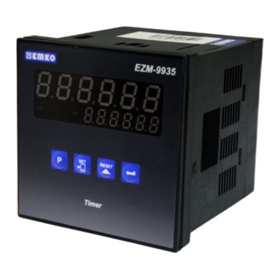
EZM-9935 96 x 96 DIN 1/4
Universal Input Programmable Timer
-
6 digits Process (PV) and 6 digits Set (SV) Value Display
- Operation with 1 Set Value
- Reset , Pause and Start Inputs
-
Operation with Automatic and Manual Reset
-
NPN/PNP Type Operation
- Programmable Time Bases (Second, Minute, Hour)
Introduction Manual. ENG EZM-9935 02 V01 07/14
Advertisement
Table of Contents

Subscribe to Our Youtube Channel
Related Manuals for EMKO EZM-9935


Summary of Contents for EMKO EZM-9935
- Page 1 6 digits Process (PV) and 6 digits Set (SV) Value Display - Operation with 1 Set Value - Reset , Pause and Start Inputs Operation with Automatic and Manual Reset NPN/PNP Type Operation - Programmable Time Bases (Second, Minute, Hour) Introduction Manual. ENG EZM-9935 02 V01 07/14...
- Page 2 ABOUT INSTRUCTION MANUAL Instruction manual of EZM-9935 Programmable Timer consists of two main sections. Explanation of these sections are below. Also, there are other sections which include order information and technical specifications of the device. All titles and page numbers in instruction manual are in “CONTENTS”...
-
Page 3: Table Of Contents
3.4 CONNECTION OF DEVICE SUPPLY VOLTAGE INPUT 3.5 INPUT CONNECTION 3.5.1 PROXIMITY CONNECTION 3.5.2 SWITCH CONNECTION 3.6 RELAY OUTPUT WIRING DIAGRAM 3.7 GALVANIC ISOLATION TEST VALUES OF EZM-9935 PROGRAMMABLE TIMER 4.DEFINITION OF FRONT PANEL AND ACCESSING TO THE SET PARAMETERS......................Page 19 4.1 DEFINITION OF FRONT PANEL... - Page 4 EU DECLARATION OF CONFORMITY Manufacturer Company Name : Emko Elektronik A.S. Manufacturer Company Address: DOSAB, Karanfil Sokak, No:6, 16369 Bursa, Turkiye The manufacturer hereby declares that the product conforms to the following standards and conditions. Product Name : Programmable Timer...
-
Page 5: Preface
Some application fields which they are used are below: Application Field Package machines, Quality Control rollers, Filling Systems, Tool Benchs, Building Automation. Production bands 1.1 General Specifications EZM-9935 Standart 230 V 50/60Hz Supply Voltage Input Optional Supply Input 115V 50/60Hz, 24V... -
Page 6: Ordering Information
Symbol means Vdc 1.3 Warranty EMKO Elektronik warrants that the equipment delivered is free from defects in material and workmanship. This warranty is provided for a period of two years. The warranty period starts from the delivery date. This warranty is in force if duty and responsibilities which are determined in warranty document and instruction manual performs by the customer completely. -
Page 7: Installation
2.Installation Before beginning installation of this product, please read the instruction manual and warnings below carefully. In package , - One piece unit - Two pieces mounting clamps - One piece instruction manual A visual inspection of this product for possible damage occured during shipment is recommended before installation. -
Page 8: General Description
(maximum thickness 15 mm / 0.59 inch) Front Panel IP65 protection NEMA 4X 2.2 Dimentions Maximum 15 mm / 0.59 inch EZM-9935 RESET Timer 96 mm / 3.78 inch 11.5 ± 1 mm / 0.45 inch 84mm / 3.31 inch... -
Page 9: Panel Cut-Out
2.3 Panel Cut-out 129 mm / 5.08 inch (min) 92 mm / 3.62 inch... -
Page 10: Environmental Ratings
2.4 Environmental Ratings Operating Conditions Operating Temperature : 0 to 50 °C Max. Operating Humidity : 90% Rh (non-condensing) Altitude : Up to 2000m. Forbidden Conditions: Corrosive atmosphere Explosive atmosphere Home applications (The unit is only for industrial applications) 2.5 Panel Mounting 1-Before mounting the device in your panel, make sure that the cut-out is the right size. -
Page 11: Installation Fixing Clamp
2.6 Installation Fixing Clamp The unit is designed for panel mounting. 1-Insert the unit in the panel cut-out from the front side. 2- Insert the mounting clamps to the holes that located top and bottom sides of device and screw up the fixing screws until the unit completely immobile within the panel... -
Page 12: Electrical Wirings
Keep the power off until all of the wiring is completed so that electric shock and trouble with the unit can be prevented. 3.1 Terminal Layout and Connection Instructions P/N : EZM-9935 Max. 2.5mm / 0.098 inch Wire Size: 14AWG/1mm²... -
Page 13: Electrical Wiring Diagram
3.2 Electrical Wiring Diagram Electrical wiring of the device must be the same as ‘Electrical Wiring Diagram’ below to prevent damage to the process being controlled and personnel injury. P/N : EZM-9935 5A@250V 1 2 3 4 5 11 12 13... -
Page 14: View Of Device Label
3.3 View of Device Label P/N : EZM-9935 230 V ± 50/60 Hz - 2.3VA 5A@250V 11 12 13 14 15... -
Page 15: Connection Of Device Supply Voltage Input
3.4 Connection of Device Supply Voltage Input Connection of Universal Connection of Universal Supply Voltage Input Supply Voltage Input External External Fuse Fuse (1 A (1 A Power Power Supply Supply Switch Switch Supply Voltage Supply Voltage 115V , 230 V (-%15;+%10) 50/60Hz (-%15;+%10) 50/60 Hz Note-1 :... -
Page 16: Input Connection
3.5 Input Connection 3.5.1 Proximity Connection PNP type operation PROX. PROX. PROX. NOTE-1 NPN type operation PROX. PROX. PROX. NOTE-1 NOTE-1 : Sensor supply voltage: 12V ± 40%, 50 mA maximum with short circuit protection... -
Page 17: Switch Connection
3.5.2 Switch Connection PNP type operation NOTE-1 NPN type operation NOTE-1 NOTE-1 : Sensor supply voltage: 12V ± 40%, 50 mA maximum with short circuit protection... -
Page 18: Relay Output Wiring Diagram
(Contactor) Fuse Load Fuses must be selected according to the applications. 3.7 Galvanic Isolation Test Results of EZM-9930 Programmable Counter 3.7 Galvanic Isolation Test Results of EZM-9935 Programmable Timer 500V ( for EZM-9935.3 ) 2000V ( for EZM-9935.5 ) Supply Voltage... -
Page 19: Timer
4.Definition of Front Panel and Accessing to the Set Parameters 4.1 Definition of Front Panel EZM-9935 Displays Actual Value and Name of Program Parameter Led indication of output Displays SET and is active Parameter Value RESET Led indication of SV:SET... -
Page 20: Power On Observation Of Ezm - 9935 Programmable Timer
When power is applied to the device, software revision number of the controller is momentarily illuminated on actual value display. Then operation screen is observed. When power on, view of the screen is shown below: EZM-9935 RESET Revision number “ rEu” Revision... - Page 21 4.3 Adjustment of SET Value Changing SET Value SET Screen Operation Screen RESET RESET Press Shift button again. When shift button is pressed, 6th digit of SET value starts to flash. SET Screen SET Screen 4th digit of SET value starts to flash.
- Page 22 4.4 Resetting the Count Value Operation Operation Screen Screen RESET RESET When RESET button is pressed, Actual Value becomes the 0 Value. RESET operation can be realized by Reset button or applying signal to the RESET input. These two operations are named MANUAL RESET in parameters section.
-
Page 23: Accessing To The Program Parameters
4.5 Accessing to the Program Parameters In this section Accessing to the Program parameters process is shown. For details on parameters refer to PROGRAM PARAMETERS section. Operation Password Screen Screen The most significant digit of the parameter (4th digit for this parameter) flashes. - Page 24 Output Functions The most significant digit of the parameter (1st digit for this parameter) flashes. You can change the p a r a m e t e r w i t h INCREMENT button, save it to the memory and p a s s t o t h e n e x t RESET Press PROG button to exit...
- Page 25 Data Record The most significant digit of the parameter (1st digit for this parameter) flashes. You can change the p a r a m e t e r w i t h INCREMENT button, save it to the memory and p a s s t o t h e n e x t RESET Press PROG button to exit...
- Page 26 RESET RESET Time Unit and Scale Selection Operation Screen Continue to press ENTER button for scanning all parameters.
-
Page 27: Program Parameters
8. PARAMETRELER 5. Program Parameters Time Unit and Scale Selection Hour/Minute It can be adjusted from Minute/Second It can be adjusted from Second/Milisecond It can be adjusted from Hour/Minute It can be adjusted from Hour It can be adjusted from Minute It can be adjusted from Second... - Page 28 Output Functions Manual Reset-1. Device continues to count till manual reset is applied. (Output PulseTime is not considered) Count direction : 0 --> P (Upcounting) Start Reset Output When count value reaches the Set Value, Output Position is changed. Counting process continues over the SET value. Output Pulse Time is not considered.
- Page 29 Manual Reset-2. Device continues to count till manual reset is applied. (Output pulse Time is not considered) Counting direction : 0 --> P (Upcounting) Start Reset Output When count value reaches the Set Value, Output Position is changed. Counting process is not continue over the SET value. Output Pulse Time is not considered.
- Page 30 Manual Reset-3. Device continues to count till manual reset is applied. (Output Pulse Time is considered.) Counting direction : 0 --> P (Upcounting) Start Reset Output Output When count value reaches the Set Value, Output Position is changed. If Output Pulse time is not 0, then Output Position is changed at the end of the Pulse time.
- Page 31 Automatic Reset-1 Counting direction : 0 --> P (Upcounting) Start Reset Output Output When count value reaches the Set Value, Output Position is changed. Actual value is reset automatically. While Start input is active, then counting starts upcounting from 0 value. If Output Pulse time is not 0, then Output Position is changed at the end of the Pulse time.
- Page 32 Automatic Reset-2 Counting direction : 0 --> P (Upcounting) Start Reset Output Start Reset Output When count value reaches the Set Value, Output Position is changed. If Output Pulse time is not 0, then Output Position is changed at the end of the Pulse time and Actual value is reset and if the Start input is active, then counting starts from 0 value.
- Page 33 Counting direction : P --> 0 (Downcounting) Start Reset Output Start Reset Output When count value reaches the 0 Value, Output Position is changed. If Output Pulse time is not 0, then Output Position is changed at the end of the Pulse time and Actual value is reset. If the Start input is active, then counting starts from Set value.
- Page 34 Automatic Reset-3 Counting direction : 0 --> P (Upcounting) Start Reset Output Start Reset Output When count value reaches the Set Value, Output Position is changed. If Output Pulse time is not 0, then Output Position is changed at the end of the Pulse time and Real counting value is shown on Actual value screen.
- Page 35 Counting direction : P --> 0 (Downcounting) Start Reset Output Start Reset Output When count value reaches the 0 Value, Output Position is changed. If Output Pulse time is not 0, then Output Position is changed at the end of the Pulse time and Real counting value is shown on Actual value screen.
- Page 36 Automatic Reset-4 Counting direction : 0 --> P (Upcounting) Start Reset Output Start Reset Output When count value reaches the Set Value, Output Position is changed. If Output Pulse time is not 0, then Output Position is changed at the end of the Pulse time and counting value becomes 0 and output becomes inactive position.
- Page 37 Counting direction : P --> 0 (Downcounting) Start Reset Output Start Reset Output When count value reaches the 0 Value, Output Position is changed. If Output Pulse time is not 0, then Output Position is changed at the end of the Pulse time and counting value becomes Set value and output becomes inactive position.
- Page 38 Automatic Reset-5 is not considered. Counting direction : 0 --> P (Upcounting) Start Reset Output If the Start input is active, then Process starts counting, until count value reach SET value. When count value reach SET value, Output Position becomes active position and process is automatically reset. If the Start input is active, then process start counting from “0”...
- Page 39 Output Run Type Output Normally non-energised Output Normally energised Output Pulse Time It determines how long Output will be active. It can be adjusted from 00.00 to 99.99 seconds. For details, refer to the section where output functions defined Direction of Counting Upcount.
- Page 40 Program Password It is used for accessing to the program parameters. It can be adjusted from If it is , there is no password protection while accessing to the parameters. When programming button is pressed, will appear on the display. If program password is not “0”...
-
Page 41: Failure Messages In Ezm-9935 Programmable Timer
6. Failure Messages in EZM-9935 Programmable Timer 1-If the password is not 0, user can access to the parameters without entering the password and by pressing ENTER button. User can see all parameters except for programming password parameter but user can not do any changes in parameters. - Page 42 RESET RESET Operation Screen Time Unit and Scale Selection 2-If Actual Value is flashing and counting is stopped ; It appears if any of the count value is greater than the maximum count value. To remove this warning and reset the count value press RESET button.
-
Page 43: Specifications
Emko Elektronik Sanayi ve Ticaret A.Þ. Demirtaþ Organize Sanayi Bölgesi Karanfil Sk. No:6 16369 BURSA/TURKEY Phone : +90 224 261 1900 Fax : +90 224 261 1912 Thank you very much for your preference to use Emko Elektronik Products. Your Technology Partner www.emkoelektronik.com.tr...
Need help?
Do you have a question about the EZM-9935 and is the answer not in the manual?
Questions and answers