Table of Contents
Advertisement
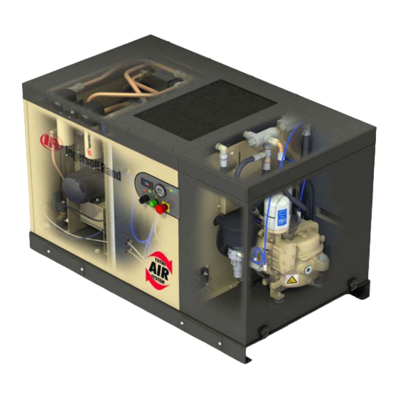
Nirvana 5.5 - 11kW (7.5 – 15 HP)
Variable Speed Drive
T1
T2
Technicians
Diagnostics and
troubleshooting
Guide
Danger
1
Please utilise extreme caution when performing work within the compressor. Wear appropriate PPE
Revision 02, July 2008
(Personal Protective Equipment), follow lock out-tag out procedures, and ensure all safety procedures.
Advertisement
Table of Contents

Related Manuals for Ingersoll-Rand Nirvana 5.5


Summary of Contents for Ingersoll-Rand Nirvana 5.5
- Page 1 Nirvana 5.5 - 11kW (7.5 – 15 HP) Variable Speed Drive Technicians Diagnostics and troubleshooting Guide Danger Please utilise extreme caution when performing work within the compressor. Wear appropriate PPE Revision 02, July 2008 (Personal Protective Equipment), follow lock out-tag out procedures, and ensure all safety procedures.
- Page 2 Copyright Notice © 2001 Ingersoll-Rand Company Proprietary Notices and Disclaimer PROPRIETARY NOTICES Copyright 2001 Ingersoll-Rand company Confidential and trade secret information. This manual contains confidential and trade secret information owned by Ingersoll-Rand Company (hereinafter referred to as "Proprietary Matter"). In consideration of the disclosure of the Proprietary Matter herein to the authorised recipient hereof, the recipient shall treat the Proprietary Matter as secret and confidential;...
-
Page 3: Table Of Contents
Table of Contents Page • General Run and Monitor Information • Secure disable • User 1 • OI-AC Over current • Motor I • Blank CDC • Other fault codes • Appendix 1: sec disable information • Appendix 2: User 1 information •... -
Page 4: General Run And Monitor Information
Safety Danger of Hazard •The drive has various voltages present on the power terminal blocks and in cables connected to them that may cause fatal electrical shocks. •The drive contains capacitors which remain charged at a fatal voltage for a period of time even after the power supply has been removed. - Page 5 IMPORTANT!! Run and Monitor. This step means that each time it will be necessary to check: • Power Input Voltage displayed and compare with your meter between each phases. • DC Bus Voltage displayed and compare with your meter. (See below restrictions regarding the Input and DC Bus voltage) •...
- Page 6 WINDING INSULATION TEST (MEGGER). • Isolate compressor from incoming Power Supply. • Disconnect motor leads from the VSD. • Connect one cable of the Insulation Tester on the main ground Connect the other cable of the megohmmeter (Insulator Tester) to each motor leads (one at a time, make sure you disconnect the brass bars from the stator connection bloc).
-
Page 7: Secure Disable
SECURE DISABLE” FAULT TREE “ Unit trips while running Power outage is unlikely More than 3 consecutive “sec.disable” fault in the memory Compressor Trips on “Sec Disable” while Check connections on E-stop (ESA1 technician on site? – Toggle switch still on and ESA2) –... -
Page 8: User 1
Continuity OK ? Phase I-II harness Swap drive – Mount a Nirvana harness new drive – Problem fixed or contact Ingersoll Rand Molex connector ok Cable cut or disconnected between (male and female drive inputs and hats parts well connected... - Page 9 “USER 1” FAULT : compressor trips on « User 1 » on regular basis or after few minutes of running Prior to troubleshoot the unit, let it cool down for 15 minutes Problem likely to be due to : -Cooling issue: -Dusty pre-filter -Blocked coolant cooler -Blower not rotating (circuit breaker, fuses, fan...
-
Page 10: Oi-Ac Over Current
“OI-AC OVER CURRENT” : peak current that exceeds the hardware limit of the drive Check power supply cables – Everything OK ? Repair or replace cables Check NDE bearing & airend – OK? Replace NDE bearing or /& airend Disconnect the output leads of the drive Megger the stator (500V D.C.) Insulation resistance <... -
Page 11: Motor I 2 T
“Motor I²t” : motor current (4.01) exceeds value set in parameter 5.07 Should go through similar process if: High voltage drive: current > 23 Amps Low voltage drive: current > 45amps Check parameter 5.07 Contact Ingersoll High voltage drive : 5.07 = 34 Amps Rand Low voltage drive : 5.07 = 54 Amps Reset the fault... -
Page 12: Blank Cdc
CDC DOES NOT WORK ON THE COMPRESSOR – FAULT TREE Situation : CDC that works on other compressors does not work on a particular unit Compressor runs (provides compressed air) ? Reconnect/replace Open drive – Check all cables – Problem Voltage on power Power cables OK ? -
Page 13: Other Fault Codes
See User1 situation page 9, check current drawn from User 2 Drive stator, if all checks are good, replace drive. Contact Ingersoll Rand (bad setting or defective drive) Electronic 24 Volt The load on the 24V supplx exceeds the maximum current Power Supply that the supply can provide. -
Page 14: Appendix 1: Sec Disable Information
•Wiring issues or loose connections within the drive (harness connected to the drive) or with the E-stop (8.09 turns to 0 any time the SDI1 input is no longer connected to the +24V supply) •Vibrations related issue (relays in the drive opens due to vibrations) – Contact Ingersoll Rand. Danger Please utilise extreme caution when performing work within the compressor. - Page 15 Appendix 1 cont. “SECURE DISABLE” FAULT – GENERAL INFORMATION Importance of knowing the frequency of “Secure Disable” fault. Depending on the frequency with witch the drive trips on “Sec. Disable”, we can consider that some explanations are more likely than others. •If there is a problem with the wiring, the connections, the E-stop or a problem of vibration, we can expect the drive to trip several times a day or even an hour.
-
Page 16: Appendix 2: User 1 Information
Appendix 2 “USER 1” FAULT – GENERAL INFORMATION •What is the “USER 1” fault? The compressors are fitted with one or two thermal sensors (depending on the generation of the compressor) to detect any overheating and stop the unit when the temperatures are over the limits. –... -
Page 17: Appendix 3: Cdc
Appendix 3 When plugged into the RJ45, this will allow the technician to have access to the drive internal values for troubleshooting. The connection for the CDC is located under the compressor canopy. No attempt should be made to tamper with the CDC parameters and adjustments must not be made to the original settings. -
Page 18: Appendix 4: Intellikey
Appendix 4 RJ45 connector is used for the Intellikey and the read only CDC. Down for variable speed, and Up for fixed speed. The potentiometer is for setting the desired pressure, by rotating Left or Right. Always check: Intellikey being used is compatable with the Machine. Turn the “On/Off”... -
Page 19: Appendix 5: Other Faults
Appendix 5 Check the E-stop position to ensure the E-stop has not been depressed. Look at the compressor display indicator to see if the compressor has reached it's maximum pressure. If maximum pressure has been Compressor has power reached, compressor will not start. but will not start Plug in CDC to view parameter 8.02, the display should read DISABLED. -
Page 20: Appendix 6: Cdc Parameters
Appendix 6 With the CDC you will have access to all of these parameters when using the Up Down arrows. ( High voltage ) Factory Settings HV (380-460 Volts) 11kW / 10bar 11kW / 8bar 7.5kW / 10bar 7.5kW / 8bar 5.5kW / 10bar 5.5kW / 8bar 15HP / 150PSI 15HP / 115PSI 10HP / 150PSI 10HP / 115PSI 7.5HP / 150PSI 7.5HP / 115PSI 1.06 Limit Maximum (speed) - Page 21 Appendix 6 cont. With the CDC you will have access to all of these parameters when using the Up Down arrows. ( High voltage ) Factory Settings HV (380-460 Volts) 11kW / 14bar 7.5kW / 14bar 15HP / 200PSI 10HP / 200PSI 1.06 Limit Maximum (speed) 4750...
- Page 22 Appendix 6 cont. With the CDC you will have access to all of these parameters when using the Up Down arrows. ( Low Voltage ) Factory Settings LV (200-230 Volts) 11kW / 10bar 11kW / 8bar 7.5kW / 10bar 7.5kW / 8bar 5.5kW / 10bar 5.5kW / 8bar 15HP / 150PSI 15HP / 115PSI 10HP / 150PSI 10HP / 115PSI 7.5HP / 150PSI 7.5HP / 115PSI 1.06 Limit Maximum (speed)
-
Page 23: Appendix 7: Indicator
Appendix 7 Nirvana 5.5-11kW Indicator Display Menu Power-Up / Default Screen - Displays Pressure in PSI, Bar or kPa. The indicator will revert back to the default screen from anywhere in the menu after approx 15 seconds of inactivity. Pressing the button navigates down through the following screens. - Page 24 Appendix 7 cont. Annual Maintenance Timer - Displays the percentage of time remaining until service should be performed. (8760 hours) The hourglass icon will flash on and off when the compressor is running and on continuously when the compressor is not running. Package Discharge Pressure in PSI - Displays the Package Discharge Pressure in PSI.
- Page 25 Appendix 7 cont. Configuration Menu Pressing and holding the button for 3 seconds will enter the configuration menu. The following screens can be viewed and manipulated. Exiting the configuration menu is accomplished by allowing the indicator to remain idle for approximately 30 seconds or by pressing and holding the button for 3 seconds.
- Page 26 Appendix 7 cont. Alerts Maintenance Due Soon - Collect Parts Maintenance Due Maintenance Past Due Compressor Fault Danger Please utilise extreme caution when performing work within the compressor. Wear appropriate PPE (Personal Protective Equipment), follow lock out-tag out procedures, and ensure all safety procedures.
-
Page 27: Appendix 8: Electrical Schematics
Appendix 8 ELECT. SCHEMATIC 4 WIRE W/ NEUTRAL & PE Danger Please utilise extreme caution when performing work within the compressor. Wear appropriate PPE (Personal Protective Equipment), follow lock out-tag out procedures, and ensure all safety procedures. - Page 28 Appendix 8 cont. ELECT. SCHEMATIC 4 WIRE W/ NEUTRAL & PE Danger Please utilise extreme caution when performing work within the compressor. Wear appropriate PPE (Personal Protective Equipment), follow lock out-tag out procedures, and ensure all safety procedures.
- Page 29 Appendix 8 cont. Danger Please utilise extreme caution when performing work within the compressor. Wear appropriate PPE (Personal Protective Equipment), follow lock out-tag out procedures, and ensure all safety procedures.
-
Page 30: Appendix 9: Site Log Form
Appendix 9 Site log form to be completed electronically ( form available on irpartner.net) to be attached with Tavant claim on main motor or VSD drive Danger Please utilise extreme caution when performing work within the compressor. Wear appropriate PPE (Personal Protective Equipment), follow lock out-tag out procedures, and ensure all safety procedures. -
Page 31: Appendix 10: Revision Number
Appendix 10 Revision number First issue, 30.06.08 Revision 2; 23.07.08 Page 18 The following text was replaced: “Switch on/off switch on position off (phase II and Nirvana), press the E-stop, remove compressor canopy and then insert the Intelli Key.” New text as follows: “Turn the “On/Off” switch to the OFF position (phase II and Nirvana), press the E-stop, remove compressor canopy and then insert the Intelli Key.”...
Need help?
Do you have a question about the Nirvana 5.5 and is the answer not in the manual?
Questions and answers