Table of Contents
Advertisement
Advertisement
Table of Contents

Related Manuals for Ingersoll-Rand 4TXM6518A1


Summary of Contents for Ingersoll-Rand 4TXM6518A1
-
Page 2: Warnings And Cautions
Warnings and Cautions Warnings and Cautions. Notice that warnings and cautions appear at appropriate intervals throughout this manual. Warnings are provided to alert installing contractors to potential hazards that could result in personal injury or death, while cautions are designed to alert personnel to conditions that could result in equipment damage. -
Page 3: Table Of Contents
In line with the company’s policy of continual product improvement, the aesthetic and dimensional characteristics, technical data and accessories of this appliance may be changed without notice. GENERA L INFORMATION CONTENTS Conformity And Range The Instructions Before Use Name of Parts Technical Data Outdoor Unit Working Temperature Range Electrical Connections... -
Page 4: The Instructions Before Use
THE INSTRUCTIONS BEFORE USE GENERA L INFORMATION WARNING Never cut off or damage power If you experience a burning Install a separate disconnect at the cables and control wires. If the smell or smoke, turn off the outdoor unit. The power supply, wiring power cable and signal control wire power supply and contact and grounding of equipment must... -
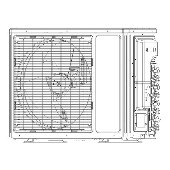
Page 5: Name Of Parts
GENERAL INFORMATION NAME OF PARTS 4TXM6518A1020BA Warning Be sure to cut off the power supply before cleaning the air conditioner; otherwise electric shock might happen. Wetting of air conditioner may cause the risk of electric shock. Make sure not to wash your air conditioner in any case. -
Page 6: Technical Data
GENERA L INFORMATION TECHNICA L DATA MODE 4TXM6518A1020BA Electrical data Electricity supply 208/230V/1~60Hz Fuse or air switch Minimum power cable section 12 AWG Refrigerant gas(R410A) Size and clearance 32.2 15.0 23.5 21.7 14.0 TECHNICAL DATA GENERA L INFORMATION MODE 4TXM6530A1040BA 4TXM6524A1030BA Electrical data Electricity supply... -
Page 7: Electrical Connections
ELECTRICAL CONNECTIONS ELECTRICAL CONNECTIONS INS TALLER INS TALLER 4TXM6518A1020BA 1. R emove the handle at the right side plate of the 4TXM6518A1020BA outdoor unit (six screw). Remove the cable clamp, connect the connection cable and power cable with the terminal at the row of connection and tighten the connection. - Page 8 ELECTRICAL CONNECTIONS INS TALLER 4TXM6524A1030BA 1. Remove the handle at the right side plate of the outdoor unit (ten screw). Remove the cable clamp, connect the connection cable and power cable with the terminal at the row of connection and tighten the connection. The fitting line distributing must be consistent with the indoor unit terminal of line bank.
- Page 9 ELECTRICAL CONNECTIONS INS TALLER 4TXM6530A1040BA 1. Remove the handle at the right side plate of the connection cable outdoor unit (ten screw). Remove the cable clamp, connect the connection cable connection cable and power cable with the terminal at the row of connection and tighten the connection.
- Page 10 ELECTRICAL CONNECTIONS INS TALLER 4TXM6542A1050BA connection cable E 1. Remove the handle at the right side plate of the outdoor unit (ten screw). connection cable Remove the cable clamp, connect the connection cable connection cable and power cable with the terminal at the row of connection and tighten the connection.
-
Page 11: Installing The Outdoor Unit
INSTALLING THE OUTDOOR UNIT INSTALLER Warning and Caution Use bolts to secure the unit to a flat, solid floor. Install the drain fitting and the drain hose(for When mounting the unit on a wall or the roof, make model with heat pump only) sure the support is firmly secured so that it cannot Condensation is produced and flows from the outdoor unit move in the event of intense vibrations or a strong... -
Page 12: Maintenance
MAINTENANCE INSTALLER Warning and Caution Use suitable instruments for the refrigerant R410A. Do not use any other refrigerant than R410A. Do not use mineral oils to clean the unit. INSTALLER INSTALLATION DIMENSION DIAGRAM Warning and Caution The installation must be done by trained and qualified service personnel with reliability according to this manual. Contact service center before installation to avoid the malfunction due to unprofessional installation. -
Page 13: Check After Installation
CHECK AFTER INSTALLATION INSTALLER Check Items Problems due to Improper Installation Is the installation reliable? The unit may drop, vibrate or make noises Has the gas leakage been checked? May cause unsatisfactory cooling (heating) effect Is the thermal insulation of the unit May cause condensation and water dropping sufficient? Is the drainage smooth? - Page 14 NOTICE: SYSTEM CONTROL LOGIC WITH MULTI SPLIT APPLICATIONS 1. With Multi Split systems, there will be a Mode Priority established by the first indoor unit to be started. All other indoor units must follow this Mode Priority which will limit the operations allowed. This logic is required as there will be different indoor units connected to one outdoor unit and opposing modes are not allowed simultaneously.
Need help?
Do you have a question about the 4TXM6518A1 and is the answer not in the manual?
Questions and answers