Advertisement
Quick Links
WARNING!
PLEASE ENSURE
that (4) steel spacers are in place
between Board Frame and Rim
Prior to tightening bolts.
(SEE PAGE 25)
FAILURE TO FOLLOW OPERATING
INSTRUCTIONS COULD RESULT
IN INJURY OR DAMAGE TO
PROPERTY.
This manual, accompanied by sales receipt, should be saved and kept on hand as a convenient reference, as it contains
WARNING!
READ AND UNDERSTAND
OPERATOR'S MANUAL
BEFORE USING THIS
UNIT.
FAILURE TO
FOLLOW OPERATING
INSTRUCTIONS COULD
RESULT IN INJURY OR
DAMAGE TO PROPERTY.
Write Model Number From Box Here:
Toll-Free Customer Service Number for U.S: 1-800-558-5234, For Canada: 1-800-284-8339,
For Europe: 00 800 555 85234 (Sweden: 009 555 85234), For Australia: 1300 367 582
© COPYRIGHT 2018 by Russel Brands, LLC
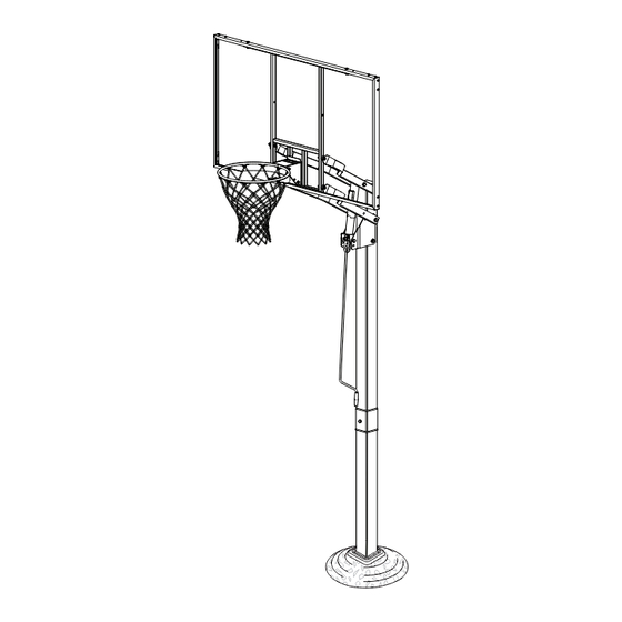
In-Ground Basketball System
Owners Manual
Adult Assembly Required.
important information about your model.
Internet Address: www.spalding.com www.spalding.com.au
REQUIRED TOOLS AND MATERIALS:
• Two (2) Capable
• Sawhorse or Support Table
Adults
• Carpenter's Level
• Stepladder 8 ft. (2.4 m)
• 15' Tape Measure
• Safety Goggles
• (2 each) Wrenches and/or Socket Wrenches and
• Shovel & Post Hole
Sockets (Deep-Well Sockets are Recommended).
Digger
• Wood Board (scrap)
• Heavy Duty Tape
1
•
• Container to Mix
• Drill
• Optional: Large &
Small Adjustable
Wrenches
1/2"
9/16"
3/4"
• Optional: Clamps
1/2"
9/16"
3/4"
07/18
ID# M888A410
Advertisement

Related Manuals for SPALDING M888A410


Summary of Contents for SPALDING M888A410
- Page 1 3/4” Toll-Free Customer Service Number for U.S: 1-800-558-5234, For Canada: 1-800-284-8339, For Europe: 00 800 555 85234 (Sweden: 009 555 85234), For Australia: 1300 367 582 Internet Address: www.spalding.com www.spalding.com.au © COPYRIGHT 2018 by Russel Brands, LLC 07/18 ID# M888A410...
- Page 2 Gebührenfreie Telefonnummer für die USA: 1-800-558-5234, für Kanada: 1-800-284-8339, für Europa: 00 800 555 85234 (Schweden: 009 555 85234), für Australien: 1300 367 582 Internet-Adresse: www.spalding.com www.spalding.com.au Número telefónico sin costo del Departamento de Servicio al Cliente en EE.UU.: 1-800-558-5234, Para Canadá: 1-800-284-8339, Para Europa: 00 800 555 85234 (Suecia: 009 555 85234), Para Australia: 1300 367 582...
-
Page 3: Outils Et Matériel Requis
OUTILS ET MATÉRIEL BENÖTIGTE WERKZEUGE UND HERRAMIENTAS Y REQUIS: MATERIALIEN: MATERIALES REQUERIDOS: • Zwei (2) zur Ausführung dieser • Deux (2) adultes capables • Dos (2) adultos capaces Arbeit fähige Erwachsene • Mètre • Cinta de medir • Maßband • Tabla de madera (un • Holzstück (Ausschuß) • Planche en bois (chute) trozo) • Wasserwaage • Nivel de carpintero • Niveau à bulle • Sägebock oder Stütztisch • Caballete o mesa de • Chevalet de sciage ou apoyo table • Hochstrapazierfähiges • Cinta adhesiva fort • Ruban extra-fort Klebeband • Escalera de mano de 8 • Stufenleiter, 2,4 m (8 Fuß) - Page 4 Para la última información de garantía del sistema de baloncesto Por favor visite el sitio web de Spalding Basketball en www.Spalding.com 1-800-558-5234 Póngase en contacto con servicio al cliente de Spalding en teléfono # Para obtener más información sobre piezas y garantía, visite www.Spalding.com ID# M8809A41...
-
Page 5: Safety Instructions
SAFETY INSTRUCTIONS FAILURE TO FOLLOW THESE SAFETY INSTRUCTIONS MAY RESULT IN SERIOUS INJURY, PROPERTY DAMAGE AND WILL VOID WARRANTY. Owner must ensure that all players know and follow these rules for safe operation of the system. To ensure safety, do not attempt to assemble this system without following the instructions carefully. Proper and complete assembly, use and supervision is essential for proper operation and to reduce the risk of accident or injury. A high probability of serious injury exists if this system is not installed, maintained, and operated properly. -
Page 6: Instrucciones De Seguridad
SICHERHEITSHINWEISE EIN MISSACHTEN DIESER SICHERHEITSHINWEISE KANN ZU SCHWEREN VERLETZUNGEN UND/ODER SACHSCHÄDEN FÜHREN UND MACHT DIE GARANTIE UNWIRKSAM. Der Eigentümer muss sicherstellen, dass alle Spieler diese Regeln für einen sicheren Betrieb des Systems kennen und befolgen. Aus Sicherheitsgründen darf dieses System nur unter sorgfältiger Beachtung der Anleitung zusammengebaut werden. Eine ordnungsgemäße und vollständige Montage, Verwendung und Aufsicht ist für den richtigen Betrieb und zur Reduzierung des Unfall- oder Verletzungsrisikos absolut erforderlich. Bei einer unsachgemäßen Installation und Wartung und bei einem falschen Betrieb dieses Systems besteht ein hohes Risiko schwerer Verletzungen. Den ganzen Karton und alle darin befindlichen Verpackungsmaterialien auf Bauteile und/oder zusätzliche Anleitungen inspizieren. - Page 8 BEFORE YOU START! AVANT DE COMMENCER ! VORBEREITENDE MASSNAHMEN ¡ANTES DE COMENZAR! Des questions ou des ¿Tiene preguntas o le faltan piezas? pièces manquantes? STOP! ¡ALTO! NE RETOURNEZ PAS au magasin! ¡NO regrese a la tienda! Appelez le numéro du service clientèle ¡Llame al número telefónico GRATUITO de Servicio (NUMÉRO GRATUIT) qui figure en première page! al Cliente que se indica en la primera página!
- Page 9 TRANSPORT. S’IL EST FISSURÉ, IL RISQUE DE SE CASSER SUBITEMENT. SI LE PANNEAU EST ENDOMMAGÉ D’UNE QUELCONQUE MANIÈRE AVANT OU APRÈS L’ASSEMBLAGE, APPELEZ LE NUMÉRO SANS FRAIS: États-Unis 1-800-558-5234; CANADA: 1-800-284-8339; http://www.spalding.com BEI EINEM MIT EINER ACRYL-RÜCKWAND AUSGESTATTETEN SYSTEM DIE KORBWAND AUF EVENTUELLE SCHÄDEN UNTERSUCHEN, DIE WÄHREND DES VERSANDS EINGETRETEN SEIN KÖNNEN.
- Page 10 PARTS LIST - See Hardware Identifier Item Qty. Part No. Description Item Qty. Part No. Description 901074 Top Pole Section 201651 Spacer, Plastic, 1/4” Thick 600052 Pole Cap, Square 265533 Washer, 1/2 I.D. 901075 Bottom Pole Section 220140 Screw, Pan Head 1/4 x .50 Self Tapping, Blk 206500 Ground Sleeve, Square 203100...
- Page 11 TEILELISTE - Siehe Teileschlüssel Artikel Menge Tel-Nr. Bezeichnung Artikel Menge Tel-Nr. Bezeichnung 265500 Sechskantkopfschraube, 1/2-13 x 1 Länge 901074 Oberes Stangenteil 206278 Abstandsstück, 3/4 Außendurchmesser x 4,325 600052 Stangenkappe, viereckig 201651 Abstandsstück, Plastik, 1/4 Dicke 901075 Unteres Stangenteil 265533 Nylon-Unterlegscheibe 206500 Bodenmuffe, viereckig 220140 Schraube, Panoramieren Sie Kopf 1/4 X .50 203063...
- Page 12 HARDWARE IDENTIFIER (BOLTS AND SCREWS) / IDENTIFICATION DES PIÈCES (BOULONS ET VIS) BEFESTIGUNGSTEILESCHLÜSSEL (BOLZEN UND SCHRAUBEN) / IDENTIFICADOR DE HERRAJE (PERNOS Y TORNILLOS) #13 (3) #23 (2) #19 (1) #29 (4) #27 (2) #9 (4) SCREW,PAN HD TAPPING,1/4X.50,TYPE II-BT,BLACK 220140 #8 (2) #36 (1) PN 205679 BOLT,HEX HD 1/2-13 X 2", 1.5” THREAD, ZINC PLTD HARDWARE IDENTIFIER (NUTS AND WASHERS) / IDENTIFICATION DES PIÈCES (ÉCROUS ET RONDELLES) BEFESTIGUNGSTEILESCHLÜSSEL (MUTTERN UND UNTERLEGSCHEIBEN) / IDENTIFICADOR DE HERRAJE (TUERCAS Y ARANDELAS) #6 (4) #5 (2) #18 (10) #26 (2) #42 (4)
- Page 13 IMPORTANT! WRITE MODEL NUMBER FROM BOX ONTO PAGE 1 OF THIS OWNERS MANUAL IMPORTANT! Notez à la page 1 de ce manuel votre numéro de modèle qui se trouve sur la boîte ! WICHTIG! Notieren Sie sich die Modellnummer von der Verpackung auf Seite 1 dieses Benutzerhandbuchs! ¡IMPORTANTE! Escriba en la página 1 de este manual el número de modelo que se encuentra en la caja! Correctly identify each pole section.
- Page 14 Insert bottom pole section (3) into ground sleeve (4). (SEE FIGURES A & B) Insérez la section de poteau inférieure (3) dans le manchon de fixation en terre (4). (VOIR DES FIGURES UN & B) Das untere Stangenteil (3) in die Bodenmuffe (4) einsetzen. (Siehe FIGUREN EINEN &...
- Page 15 INSTALLATION OF GROUND SLEEVE & POLE - LOCATION & DEPTH SPECIFICATIONS L’INSTALLATION DE FONDE MANCHE & POLONAIS - L’EMPLACEMENT & LES SPECIFICATIONS DE PROFONDEUR INSTALLATION VON ERDET ÄRMEL & STANGE - ORT & TIEFEN SPEZIFIKATIONEN LA INSTALACION DE MOLIO MANGA & ASTA - POSICION & ESPECIFICACIONES DE PROFUNDIDAD CRITICAL 18”...
- Page 16 Insert ground sleeve (4) and bottom pole (3) into hole. Fill remaining hole with concrete. Tamp down concrete to release air pockets and build drainage hill up to line on groundsleeve (SEE BELOW). Center and level ground sleeve assembly in hole. Using a standard level, ensure the pole &...
- Page 17 STOP! - ARRET ! - HALT! - ¡PARADA! IMPORTANT! IMPORTANT! WICHTIG! ¡IMPORTANTE! BEFORE PROCEEDING TO NEXT STEP. CONCRETE MUST CURE! FOLLOW DIRECTIONS ON PRE-MIX OR CONCRETE PACKAGING REGARDING THE NECESSARY TIME REQUIRED TO ALLOW THE CONCRETE TO FULLY CURE. IF USING CONCRETE DELIVERED ON SITE PROFESSIONALLY, CONSULT YOUR PROVIDER FOR THIS NECESSARY INFORMATION AVANT DE PROCEDER APRES POUR MARCHER.
- Page 18 IN DER LAGE BEFINDLICHEN PERSONEN AUSGEFÜHRT MATÉRIEL ASSEMBLÉ NE PEUT ÊTRE RÉALISÉ!! STOP!! NE PROCÉDEZ À WERDEN. EIN MISSACHTEN DIESER WARNUNG KANN ZU L’ÉTAPE SUIVANTE ! APPELER LE SERVICE À LA CLIENTÈLE SPALDING À SCHWEREN VERLETZUNGEN UND/ODER SACHSCHÄDEN L’AIDE. FÜHREN.
- Page 19 Assemble rebar centering clips (11) near top and bottom of 2” rebar (10) as shown. Assemblez les entretoises de centrage de la barre d’armature (11) près du haut et du bas de la barre (10), comme illustré. Die zur Zentrierung der Versteifungsstange (11) dienenden Abstandsstücke wie gezeigt in der Nähe des oberen und unteren Endes der Stange (10) anbringen.
- Page 20 Completely seal hole at the bottom of the bottom pole with heavy-duty tape (not included) to retain rebar (10) and concrete inside. Mix concrete (approximately 100 lbs. (45.4 kg)) and fill pole 1” - 2” (2.54 - 5.0 cm) below bottom elevator hole on top pole section (1) as shown.
- Page 21 Bend back exposed top flange sections of secured ground sleeve (4). After concrete has cured, remove tape, install pole cap (11) and clamp cover (12), fit pole assembly into sleeve (4). Mark a line with tape or marker 16” (40.5cm) from bottom of pole assembly. Fit pole assembly into Ground Sleeve, ensuring a full 16”...
- Page 22 Lower clamp cover (12) over clamps and snap into proper position. Abaissez le bouchon des colliers de serrage (12) sur ces derniers et enclenchez-le en position. Die Klemmenabdeckung (12) auf die Klemmen absenken und einschnappen lassen. Baje la cubierta de la abrazadera (12) sobre las abrazaderas y conéctela a presión en la posición correcta. GSQ08.EPS 211250...
- Page 23 Beginning with top hole in left and right screw jack support plates (16 and 17), install elevator yoke (15) to pole as shown. Then secure lower holes in support plates to pole. Commencez par l’orifice supérieur des plaques de fixation de vérin à vis gauche et droit (16 et 17), installez les tubes du système élévateur (15) sur le poteau, comme illustré, puis fixez les orifices inférieurs des plaques de fixation sur le poteau.
- Page 24 Attach height decal (20) on screw jack (21). Align lower edge of decal (20) with screw jack bottom. Placer l’étiquette de hauteur (20) sur le vérin à vis (21). Alinee el borde inferior de la calcomanía (20) con la parte inferior del gato de tornillo.
- Page 25 Secure upper elevator yoke (15) to pole assembly as shown. Fixez les tubes supérieur du système élévateur (15) sur le poteau, comme illustré. Die oberen Auslegerrohre (15) wie gezeigt am Stangenaufbau befestigen. Asegure los tubos superiores del elevador (15) en el conjunto del poste, como se muestra.
- Page 26 IMPORTANT! - IMPORTANT! - WICHTIG! - ¡IMPORTANTE! Instructions for GLASS BACKBOARD - ONLY! Instructions pour le verre pannenau - UNIQUEMENT ! Anweisungen für Glas RÜCKWAND - NUR! Instrucciones de VIDRIO TABLERO - SÓLO! WARNING! AVERTISSEMENT! WARNUNG! ¡ADVERTENCIA! PLEASE ENSURE that foam pad and all 4 steel spacers are in position BEFORE attaching yokes. Failure to follow these instructions could result in personal injury or damage to property.
- Page 27 Secure elevator yokes (15) as shown. IMPORTANT! IMPORTANT! Fixez les tubes du système élévateur (15) comme illustré. WICHTIG! Die Auslegerrohre (15) befestigen. ¡IMPORTANTE! DO NOT OVER TIGHTEN! Asegure los tubos del elevador (15) en NE SERREZ PAS TROP! el conjunto del poste. NICHT ZU FEST ANZIEHEN! ¡NO APRIETE EXCESIVAMENTE! NOTE:...
- Page 28 WARNING! AVERTISSEMENT! WARNUNG! ¡ADVERTENCIA! PLEASE ENSURE that foam pad and all 4 steel spacers are in position BEFORE attaching yokes. Failure to follow these instructions could result in personal injury or damage to property. VEUILLEZ VOUS ASSURER que la mousse pad et tous les 4 entretoises en acier sont en position AVANT de fixer les chapes. Le non-respect de ces instructions peut entraîner des blessures ou des dommages à la propriété.
- Page 29 Install net (32). OUTSIDE VIEW / VUE EXTÉRIEURE / AUSSENANSICHT / VISTA EXTERNA Installez le filet (32). Das Netz (32) anbringen. Instale la red (32). Install cover plate (31) on rim (33) using self tapping screws (27) as shown (note orientation of cover plate).
- Page 30 Position looped end of height adjustment crank (30) onto hook as shown. Rotate crank handle to raise or lower backboard. View label (20) to determine approximate backboard height. Placer l’extrémité avec boucle de la manivelle (30) sur le crochet comme indiqué. Tourner la manivelle pour monter ou descendre le panneau.
- Page 31 Apply height adjustment label (34) to front of pole as shown. Collez l’étiquette d’échelle de hauteur (34) sur l’avant du poteau, comme illustré. öhenkleber (34) wie gezeigt an der Vorderseite der Stange anbringen. Aplique las calcomanías de altura (34) en el frente del poste como se muestra. HEIGHT ADJUSTMENT RÉGL HEIGHT ADJUSTMENT...
Need help?
Do you have a question about the M888A410 and is the answer not in the manual?
Questions and answers