Advertisement
Quick Links
REQUIRED TOOLS AND
MATERIALS:
• Two (2) Capable
Adults
• Tape Measure
• Wood Board
6" x 6" (scrap)
• Sawhorse or
Support Table
• Hammer
• #2 or #3 Phillips
Screwdriver
• Safety Glasses
• Step Ladder 8ft.
(2.4 m)
• (2 each) Wrenches and/
or Socket Wrenches and
Sockets (Deep-Well Sockets
are Recommended).
1/2"
9/16"
3/4"
AND/OR
1/2"
9/16"
3/4"
• Extension is Recommended.
• Garden Hose or Sand
OPTIONAL TOOLS
AND MATERIALS:
• Large and Small Adjustable
Wrenches
© COPYRIGHT 2018 by Russell Brands, LLC
NBA Arena Portable System
WARNING!
PLEASE ENSURE
that (4) steel spacers
are in place between
Board Frame and Rim
Prior to tightening bolts.
(SEE PAGE 21)
FAILURE TO FOLLOW OPERATING
INSTRUCTIONS COULD RESULT IN
INJURY OR DAMAGE TO PROPERTY.
This manual, accompanied by sales receipt, should be saved and kept on hand as a
convenient reference, as it contains important information about your model.
READ AND UNDERSTAND
OPERATOR'S MANUAL BEFORE
USING THIS UNIT.
FAILURE TO FOLLOW
OPERATING INSTRUCTIONS
COULD RESULT IN INJURY OR
DAMAGE TO PROPERTY.
Toll-Free Customer Service Number for U.S: 1-800-772-5346, For Canada: 1-800-284-8339,
For Europe: 00 800 555 85234 (Sweden: 009 555 85234), For Australia: 1300 367 582
Internet Address: www.spalding.com www.spalding.com.au
Adult Assembly Required.
WARNING!
1
Write Model Number
From Box Here:
4/18
ID# M74611A
Advertisement

Related Manuals for SPALDING NBA Arena


Summary of Contents for SPALDING NBA Arena
- Page 1 REQUIRED TOOLS AND MATERIALS: • Two (2) Capable Adults NBA Arena Portable System • Tape Measure • Wood Board 6” x 6” (scrap) • Sawhorse or Support Table • Hammer • #2 or #3 Phillips Screwdriver • Safety Glasses • Step Ladder 8ft. (2.4 m) • (2 each) Wrenches and/ or Socket Wrenches and WARNING! Sockets (Deep-Well Sockets are Recommended). PLEASE ENSURE that (4) steel spacers 1/2”...
-
Page 2: Height Adjustment
WARNING Read and understand warnings listed below before using this product. Failure to follow these warnings may result in serious injury and/or property damage. HEIGHT ADJUSTMENT Owner must ensure that all players know and follow these rules for safe operation of the system. Rotate crank handle to raise •... -
Page 3: Safety Instructions
SAFETY INSTRUCTIONS FAILURE TO FOLLOW THESE SAFETY INSTRUCTIONS MAY RESULT IN SERIOUS INJURY OR PROPERTY DAMAGE AND WILL VOID WARRANTY. Owner must ensure that all players know and follow these rules for safe operation of the system. To ensure safety, do not attempt to assemble this system without following the instructions carefully. Check entire box and inside all packing material for parts and/or additional instruction material. - Page 4 Garantía de dueños Para la última información de garantía del sistema de baloncesto Por favor visite el sitio web de Spalding Basketball en www.Spalding.com 1-800-558-5234 Póngase en contacto con servicio al cliente de Spalding en teléfono # 05/2013 www.spalding.com ID# M7409121...
- Page 5 IDENTIFY HARDWARE CARDS To make the assembly easier we have separated the hardware per section. Each hardware card is dedicated to a specific assembly area. Open each individually as you progress through the steps. Do not open them all at once. BASE TO POLE FRONT WHEEL ASSEMBLY HARDWARE CARD...
- Page 6 IF YOUR SYSTEM IS EQUIPPED WITH AN ACRYLIC BACKBOARD, EXAMINE BACKBOARD FOR ANY DAMAGE THAT MAY HAVE OCCURRED DURING SHIPMENT. CRACKS IN THE BACKBOARD COULD RESULT IN SUDDEN BREAKAGE. IF BACKBOARD IS DAMAGED IN ANY WAY PRIOR TO OR AFTER ASSEMBLY, CALL TOLL-FREE NUMBER: U.S. 1-800-558-5234; CANADA: 1-800-284-8339; http://www. spalding.com...
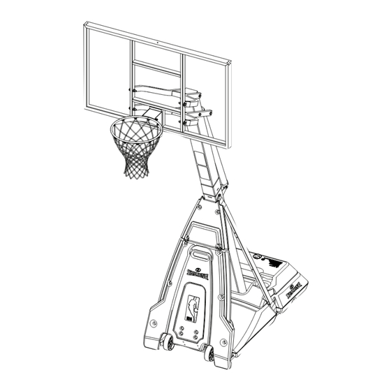
- Page 7 Get to know the basic parts of your basketball system... FRONT VIEW BACK VIEW BACKBOARD TOP POLE ELEVATOR ASSEMBLY STADIUM PAD STADIUM PAD BOTTOM BOTTOM POLE STRUTS TOP BASE BOTTOM BASE WHEEL CARRIAGE ASSEMBLY GROUND RESTRAINT ROPE...
- Page 8 SECTION A: BASE AND POLE ASSEMBLY BASE TO POLE HARDWARE CARD 208616 BA00001 HARDWARE LIST AND IDENTIFIER Item Qty. Part No. Description Item Qty. Part No. Description 600076 Top Base 265523 Bolt, Hex Head, 3/8-16 x 1” Long 901183 Bottom Pole Section 203309 Washer, Flat, 3/8 x 1 O.D. 901184 Top Pole Section 203041...
- Page 9 600074 WARNING! PRE-ASSEMBLED COMPONENTS 202900 206340 The components in steps 1 - 3 are factory pre-assembled. CHECK THE PRE-ASSEMBLED AREAS FOR TIGHTNESS. 203331 If any parts are missing or damaged please contact our 208253 customer service department to 202900 receive replacement parts (see 203309 page 1 for customer service 203331...
- Page 10 265523 265523 208253 208253 203309 203309 600075 203309 203309 203309 203309 ASSEMBLY REQUIRED Attach top base (1) to bottom base using bolts (B4), washers (B2) and nuts (B3).
- Page 11 NOTE: IF MINIMUM POLE ENGAGEMENT 5” maximum overlap of the bottom pole (2). See CAUTION! CANNOT BE ACHIEVED !! STOP!! DO NOT PROCEED TO THE NEXT STEP! - CALL SPALDING CUSTOMER SERVICE FOR ASSISTANCE. When proper range of pole assembly has been achieved, install bolt (B9), washers (B10) and nut (B11) as shown below.
- Page 12 Assemble pole to base as shown: WARNING! A. Place 4 washers (B2) onto the 4 pre-installed bolts so TWO CAPABLE ADULTS REQUIRED they rest on the nuts. FOR THIS PROCEDURE. FAILURE TO FOLLOW THIS WARNING COULD B. Rest pole on the 4 washers (B2). RESULT IN SERIOUS INJURY AND/ Allow 4 pre-attached bolts to pass through the 4 holes in OR PROPERTY DAMAGE.
- Page 13 Attach struts (4 and 5) to bottom pole (2) using bolt (B8) and nut (B6). NOTE: DO NOT fully tighten at this time. IMPORTANT! NOTE POSITION OF STRUTS Front struts, with holes (4), get placed closest to the pole. WARNING! TWO CAPABLE ADULTS REQUIRED FOR THIS PROCEDURE.
- Page 14 SECTION B: WHEEL CARRIAGE ASSEMBLY TOOLS REQUIRED FOR THIS SECTION FRONT WHEEL ASSEMBLY HARDWARE CARD (2) Wrenches 9/16” AND/OR (2) Socket Wrenches and Sockets BA00002 9/16” Extension HARDWARE LIST AND IDENTIFIER Item Qty. Part No. Description Item Qty. Part No. Description 600074 Wheel, 6” 200514 Bolt, Hex Head, 3/8-16 x 3” Long 600079 Transport Handle, Plastic 203041...
-
Page 15: Completed Assembly
A. Attach u-bracket (12) to cross member (16) using bolts (W4), washers (W3) and nuts (W2). B. Secure cross member (16) to front struts (4) using bolts (W1), washer (W3) and nuts (W2) IMPORTANT! NOTE ORIENTATION OF STRUT BRACE (16). COMPLETED ASSEMBLY IMPORTANT! NOTE ORIENTATION... - Page 16 Insert axle (17) through wheel bracket (13). Secure wheels (10) to axle using pushnuts (W9). Carefully tap pushnuts (W9) onto axle with hammer or mallet. NOTE: TO INSTALL SECOND PUSHNUT: • Assemble Pushnut, Wheels, Axle, And Wheel Bracket As Shown. •...
- Page 17 Secure lower pivot bracket (14) to wheel assembly using bolt (W7), pivot disk (15) and nut (W6). Secure wheel assembly to u-bracket (12) using bolt (W5), spacer (W10), and nut (W6). IMPORTANT! DO NOT OVER TIGHTEN BOLT (W5). Attach transport handle (11) to wheel assembly using carriage bolts (W8) and nuts (W2).
- Page 18 SECTION C: ELEVATOR ASSEMBLY PART 1 ELEVATOR TO POLE CONNECTION HARDWARE CARD EL00001 HARDWARE LIST AND IDENTIFIER Item Qty. Part No. Description Item Qty. Part No. Description 700009 Handle, Screw-Jack 201518 Bolt, Hex-Head, 5/16-18 x 2.75” Long 80034403 Screw Jack 203099 Lock-Nut, Nylon Insert, 5/16-18 60016401 Sleeve, Screw Jack 600165 Cap, Screw Jack 202528...
- Page 19 A. Securely rest the assembly on sawhorse. B. Slide screw-jack sleeve (22) over screw jack and attach cap (23) to top end. C. Attach screw-jack (21, 22, 23) to pole bracket with bolt (E1) and nut (E2) as shown. D. Attach handle (20) to screw jack with pin (24).
- Page 20 SECTION D: ELEVATOR ASSEMBLY PART 2 TOOLS REQUIRED FOR THIS ELEVATOR ARMS SECTION HARDWARE BAG (2) Wrenches 3/4” 207876 (3pcs) AND/OR (2) Socket Wrenches and Sockets 206340 (7pcs) 204620 (2pcs) 205711 (4pcs) 201651 (4pcs) 208251 (4pcs) Extension 3/4” 203474 (14pcs) AR00004 AR00004 HARDWARE LIST AND IDENTIFIER Item Qty. Part No. Description Item Qty. Part No. Description 908508 Elevator Tube, Upper...
- Page 21 While system is still resting on sawhorse, Identify elevator tubes (30 and 31). NO PAD While the system is securely resting on the sawhorse. Install elevator tubes (30 and 31) to top pole section (3) as shown. WARNING! COMPLETED ASSEMBLY WARNING! TWO CAPABLE ADULTS TIGHTEN BOLT (A5) IN...
- Page 22 IMPORTANT! - IMPORTANT! - WICHTIG! - ¡IMPORTANTE! Instructions for GLASS BACKBOARD - ONLY! Instructions pour le verre pannenau - UNIQUEMENT ! Anweisungen für Glas RÜCKWAND - NUR! Instrucciones de VIDRIO TABLERO - SÓLO! WARNING! AVERTISSEMENT! WARNUNG! ¡ADVERTENCIA! PLEASE ENSURE that foam pad and all 4 steel spacers are in position BEFORE attaching yokes. Failure to follow these instructions could result in personal injury or damage to property.
- Page 23 While the system is still resting on the sawhorse, making sure to align both the inner metal screw-jack (21) AND the outer plastic screw-jack sleeve (22) bolt holes and install screw jack assembly to lower elevator tube (31). Secure with bolt (A5), washers (A3), Spacers (A7) and nut (A2). Re-install screw-jack cap (23). WARNING! TIGHTEN BOLT (A5) IN LOCK NUT (A2) UNTIL...
- Page 24 A. Fill bottom base half-way with water (approx. 25 gallons (95 Liters)) or sand (approx. 295 of total 590 lbs. (134 of total 268 kg)). B. Set backboard to the LOWEST elevator setting C. CAREFULLY upright system. WARNING! TWO CAPABLE ADULTS REQUIRED FOR THIS PROCEDURE.
- Page 25 WARNING! Roll completed assembly to desired position. Cap (33) MUST be tightened COMPLETELY and SECURELY to prevent After system is placed in an upright position, leakage. CHECK WATER LEVEL BEFORE EACH COMPLETE the filling process in BOTH USE! FAILURE TO FOLLOW THIS bases.
- Page 26 SECTION E: ATTACH BOARD RIM RIM ATTACHMENT HARDWARE AND BAG 222700 HARDWARE LIST AND IDENTIFIER Item Qty. Part No. Description Item Qty. Part No. Description Backboard 201611 Bolt, Hex-Flange, 5/16-18 x 3” Long 203309 Washer, 3/8, 1: O.D. 203100 Nut, Hex-Flange, 5/16-18 #R1 (4) #R3 (4) #R2 (4) 203100 NUT, HEX FLANGE, 5/16-18 TOOLS REQUIRED FOR THIS SECTION...
- Page 27 WARNING! AVERTISSEMENT! WARNUNG! ¡ADVERTENCIA! PLEASE ENSURE that foam pad and all 4 steel spacers are in position BEFORE attaching yokes. Failure to follow these instructions could result in personal injury or damage to property. VEUILLEZ VOUS ASSURER que la mousse pad et tous les 4 entretoises en acier sont en position AVANT de fixer les chapes. Le non-respect de ces instructions peut entraîner des blessures ou des dommages à...
- Page 28 TO ADJUST RIM TENSION Make adjustments as shown. Tightening the nut: • Increases the preload on the spring and increases the rim’s resistance to movement. • The higher the preload, the more force required to move the rim downward. Tighten Loosen (9/16”) Install cover plate on rim (40) using self tapping screws removed in step 1 of this section (note orientation of cover plate).
- Page 29 SECTION F: STADIUM PAD AND FINALIZING SET-UP STADIUM AND BOARD PAD HARDWARE CARD AC00001 HARDWARE LIST AND IDENTIFIER Item Qty. Part No. Description Item Qty. Part No. Description 600077 Stadium Pad, Bottom 206011 Bolt, Carriage, 3/8-16 x 2.75” Long 600078 Stadium Pad, Top 203041 Nut, Hex-Flange, 3/8-16 203124 Ground Stake 574090 Label, Height Adjustment and Moving 204872...
- Page 30 STADIUM PAD - INSTALLATION Attach top stadium pad (51) with bolts (P1) and Nuts (P2). Slide bottom stadium pad (50) behind the transport handle (11) and secure with bolts (P1) and nuts (P2). NOTE: If necessary, slightly loosen bolts that secure front struts to pole and base frame (circled areas).
- Page 31 SECURING SYSTEM WITH GROUND STAKE HEIGHT Secure system by hooking loose end of rope onto ground stake (52). ADJUSTMENT CAUTION! Place stake so that when it is screwed into the ground the rope is taut. DO NOT OVER-CRANK HANDLE BEYOND THE MANUFACTURED HEIGHT- Rotate crank handle to raise INDICATOR RANGE OF and lower...
- Page 32 APPLY HEIGHT INDICATOR DECALS Apply Height Indicator Labels (54) to screw jack. Tools needed for this operation - Tape measure, Step Ladder 8 ft. Step 1 - Set unit to 7-1/2 feet (2.3 m) by adjusting the screw jack and measuring from the top of the rim to the playing surface.
Need help?
Do you have a question about the NBA Arena and is the answer not in the manual?
Questions and answers