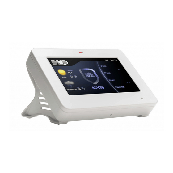
DMP Electronics XTLtouch Programming Manual
Hide thumbs
Also See for XTLtouch:
- User manual (40 pages) ,
- Installation manual (28 pages) ,
- Lab manual (3 pages)
Table of Contents
Advertisement
Quick Links
Advertisement
Table of Contents

Related Manuals for DMP Electronics XTLtouch


Summary of Contents for DMP Electronics XTLtouch
- Page 1 PROGRAMMING GUIDE DIGITAL MONITORING PRODUCTS, INC. © 2020 LT-1789 19282...
-
Page 2: Table Of Contents
CONTENTS For Your Information......1 WPS ..............6 App Key ............6 System Types ...........1 System............... 6 Compliance Instructions ......1 Hours from GMT ..........6 LED Operation ..........1 Weather Zip Code ........6 Reset Button .............1 Enter Siren Serial Number ......6 On-Board 1100 Series Wireless ....2 Zone Number .......... - Page 3 CONTENTS System Reports .......15 Alarm Reports ..........9 Receiver 2 Backup?........9 System Reports ..........15 Supervisory/Trouble Reports ....9 Opening/Closing Reports......15 Opening/Closing and User Reports ..9 Abort Reports ..........15 Test Report ............9 Zone Restoral Reports ....... 15 First IP Address ..........
- Page 4 CONTENTS Output Setup........25 Occupied Premises ........20 Use False Alarm Question .......20 Output Number ........... 25 Weather Zip Code ........20 Output Name ..........25 Celsius Temperature Option....20 Serial Number ..........25 Bell Options ........21 Supervision Time ........25 Trip with Panel Bell Option ..... 25 Bell Cutoff Time ..........
- Page 5 CONTENTS Button Action ..........32 Zone Number ..........37 Stop ..........38 Button Press Time ........32 Arm/Disarm Area Selection ....32 Set Lockout Code ......39 Output Number ........... 33 Appendix ........40 Output Action ..........33 Status List ............40 Alarm Action ..........33 Transmission Delay ........40 Disarmed Open ..........
-
Page 6: For Your Information
The RESET button is located on the back of the unit in the lower left corner under the backplate and is used to reset the XTLtouch panel. To reset the panel prior to reprogramming, press the RESET button without powering down the system. -
Page 7: On-Board 1100 Series Wireless
Wireless Key Fobs and Outputs The XTLtouch provides eight wireless key fob or output addresses numbered 51 to 54 and 61 to 64. A default name is provided as a programming convenience to help reduce installation time. The default names are described in the programming sections of this guide and can be changed in Output Information or Zone Information programming as needed. -
Page 8: Special Keys
XTLtouch such as phone numbers and zone names. As you advance through the programming menus, the XTLtouch display shows any current programming already stored in the panel memory. If no change is required for a programming option, press CMD to advance to the next option. -
Page 9: Begin Here
30 minutes, programming is terminated. All data entered up to that point is saved in the XTLtouch. To exit the Programmer menu, you must use the Stop function to save all information entered in the XTLtouch to that point. Once you exit the Programmer menu, the XTLtouch returns to the home screen. -
Page 10: Initialization
INITIALIZATION Initialization allows you to set the XTLtouch back to its factory defaults. After selecting YES to clear a memory option, the XTLtouch asks if you’re sure you want to clear that option’s memory. This safeguards you against accidentally deleting current programming. Programming isn’t cleared from XTLtouch until you answer YES to SURE? YES NO. -
Page 11: Fast Programming
FAST PROGRAMMING Fast programming allows you to quickly program the essential XTLtouch settings. When the panel programming defaults are acceptable for an installation and only basic programming options are needed, fast programming allows you to quickly enter information without navigating through all of the programming menus. -
Page 12: Communication
COMMUNICATION TYPE COMM TYPE: WIFI Press a select area to display WIFI, CEL, and NONE. Select how the XTLtouch should communicate with the receiver. The communication types are described below: WIFI: This option allows network communication to DMP Model SCS-1R or ▶... -
Page 13: Checkin Reports
If an acknowledgment isn’t received, the first Cell APN and the second IP address are used and followed, if needed, by the second Cell APN and the first and second IP addresses. Enter all 12 digits and leave out the periods. The default is 0.0.0.0. XTLtouch Series Programming Guide | Digital Monitoring Products... -
Page 14: Alarm Reports
Press a select area to enter the first IP port number that will be used with the first IP Address. The IP port identifies the port used to communicate messages to and from the panel. The default is 2001. XTLtouch Series Programming Guide | Digital Monitoring Products... -
Page 15: Second Ip Address
SECOND IP PORT SECOND IP PORT 2001 Enter the second (secondary) IP address where the panel sends network or cellular information. Enter all 12 digits and leave out the periods, they will auto-generate. XTLtouch Series Programming Guide | Digital Monitoring Products... -
Page 16: Network Options
NETWORK OPTIONS Network Options allow you to program the XTLtouch to use either Wi-Fi or Cellular communication. Keep in mind, IP addresses and port numbers may need to be assigned by the network administrator. NETWORK OPTIONS Press a select area. -
Page 17: Manual
XTLtouch is connected to the Wi-Fi network. DHCP DHCP If the XTLtouch uses a dynamic IP address, select YES to allow the XTLtouch to operate in DHCP and not use the local IP address number. LOCAL IP ADDRESS LOCAL IP ADDRESS 192.168.98.26... -
Page 18: Device Setup
Enter the device number of the wireless keypad you’re programming. The valid range is DEVICE NO: - 2-8. Keep in mind that Address 1 is reserved for the XTLtouch programming keypad that you’re using right now. Repeat the steps in this section for each additional keypad. -
Page 19: Remote Options
REMOTE OPTIONS Remote Options allows you to program the XTLtouch for Remote Command and Remote Programming operation using the Wi-Fi network. REMOTE OPTIONS REMOTE OPTIONS Press a select area. REMOTE KEY This option allows you to enter a 1 to 8-digit code to verify the authority of an alarm or RMT KEY: to allow remote connections to perform a remote command/programming session. -
Page 20: System Reports
O/C RPTS default is NO. ABORT REPORTS Select YES to allow the XTLtouch to send an Alarm Abort Report to the receiver when ABORT an area is disarmed during Transmit Delay before an alarm report is sent and the Bell Cutoff Time has not expired. -
Page 21: Late To Open
0 if regular check-ins are not programmed and is the normal fail time if check-ins are programmed. During the time frame between the beginning of the Entry Delay and the following check-in message, regular check-in messages are suspended. The default is NO. XTLtouch Series Programming Guide | Digital Monitoring Products... -
Page 22: System Options
SYSTEM OPTIONS System Options allows you to select system wide parameters used in the operation of the XTLtouch. SYSTEM OPTIONS Press a select area. SYSTEM OPTIONS SYSTEM Press a select area to choose the system type. The default is HOME/AWAY (Perimeter,... -
Page 23: Cross Zone Time
AC power is off for the length of the programmed time, an AC power failure report is sent to the receiver. Enter 0 (zero) to allow the XTLtouch to send the AC power failure report to the receiver within 15 seconds. The range is 1 to 9 hours. The default is 1. -
Page 24: Arm Activity Days
A Wireless House Code is pre-programmed at the factory. To change the house HOUSE CODE: code, press any select area and enter a number between 1 and 50. The XTLtouch automatically programs the house code into the wireless transmitters when the unique transmitter serial number is programmed into the panel. -
Page 25: Wireless Audible Annunciation
ENTER WEATHER ZIP CODE: - This option allows local U.S.A. weather updates to display on the keypad home screen. Enter the zip code of area the XTLtouch is located in. The default is blank. CELSIUS TEMPERATURE OPTION THERMOSTAT UNIT This prompt determines whether the panel should use Celsius for displayed Thermostat CELSIUS temperatures and for sending temperatures to Z-Wave Thermostats. -
Page 26: Bell Options
PANIC PANIC TYPE: N Defines Bell Action for Panic Type Zones. The default is N. EMERGENCY TYPE: N EMERGNCY Defines Bell Action for Emergency Type Zones. The default is set at N. XTLtouch Series Programming Guide | Digital Monitoring Products... -
Page 27: Auxiliary 1
Defines Bell Action for Carbon Monoxide (CO) Zone Types. The default is set at 4. ZONE MONITOR OUTPUT Defines Bell Action for Zone Monitor Zone Types. The default is set at N. ZN MNTR TYPE: XTLtouch Series Programming Guide | Digital Monitoring Products... -
Page 28: Output Options
ARMED HOME OUTPUT ARMED HOME: The entered output turns on any time the system is armed. The keypad display is dependent on the system’s arming type. For Home/Away systems, only the HOME and XTLtouch Series Programming Guide | Digital Monitoring Products... -
Page 29: Armed Away Output
Sensor Reset option while no additional CO type zones are in alarm. ZONE MONITOR OUTPUT ZN MNTR TYPE: 4 Defines Bell Action for Zone Monitor Zone Types. The default is set at N. XTLtouch Series Programming Guide | Digital Monitoring Products... -
Page 30: Output Setup
TRIP WITH PANEL BELL This option displays when the wireless device is an 1135 wireless siren. Select YES to have the 1135 wireless siren follow the panel bell output. Default is YES. XTLtouch Series Programming Guide | Digital Monitoring Products... -
Page 31: Area Information
AREA INFORMATION This section allows you to assign functions to individual areas for XTLtouch panels. All non-24-hour zones must be assigned to an active area. See the section on Zone Information. Activate an area by assigning it a name. A name is given to each active area to assist the user during arming and disarming. -
Page 32: Zone Information
ZONE NUMBER ZONE NO: - Zone numbers on the XTLtouch panel default to the following settings. The settings can be changed as described in the following sections. Zones 51-54 can be wireless zones, key fobs or slow outputs. Zones 61-64 can be wireless zones, key fobs, or fast outputs. - Page 33 If the keyswitch is held in the arming position for the full five seconds, the bad zone is force armed and the area is armed. XTLtouch Series Programming Guide | Digital Monitoring Products...
-
Page 34: Style
When the zone is opened from a normal (disarmed) state, a trouble is reported. If opened from a shorted (armed) state, an alarm is reported and the zone is disabled until you disarm the area(s) from either a keypad or RemoteLink™ computer. XTLtouch Series Programming Guide | Digital Monitoring Products... -
Page 35: Dmp Wireless
For wireless key fob programming see the 1144 Series Key Fob section. Note: All wireless programming is stored in the XTLtouch panel. Each time the panel powers up, when the programmer STOP routine is selected or the panel is reset, the wireless receiver memory refresh could take up to 45 seconds to complete depending on the number of wireless zones programmed and the Red LED remains on during this time. -
Page 36: Led Operation
Selecting YES allows pet immunity for animals up to 55 pounds. NEXT ZONE Select YES to return to the ZONE NO: - option to program a new zone. Select NO to NEXT ZN display the Alarm Action option. XTLtouch Series Programming Guide | Digital Monitoring Products... -
Page 37: 1144 Series Key Fobs
The following list identifies the default button assignments: Arming with areas 1, 2, and 3 assigned Disarming with areas 1, 2, and 3 assigned XTLtouch Series Programming Guide | Digital Monitoring Products... -
Page 38: Button Action
ARM AREAS: PERIM After selecting the areas, for one-button key fobs the Zone No.: option displays. For two-button or four-button key fobs, the Key Fob Button Selection option displays to program additional buttons. XTLtouch Series Programming Guide | Digital Monitoring Products... -
Page 39: Output Number
There are three actions to define: Message to Transmit Output Number Output Action You must also make these selections for the Disarmed Short, Armed Open, and Armed Short zone conditions. Press CMD to continue. XTLtouch Series Programming Guide | Digital Monitoring Products... - Page 40 Only the programmed Output Number activates. OUTPUT NUMBER You can specify any of the outputs on the XTLtouch to be activated by a zone condition. OUTPUT NO: The output can be activated regardless of the report to transmit or whether or not the zone is programmed as local.
- Page 41 Option is only shown for an Exit zone. Select the entry delay timer for this zone. Entry delay timers 1 and 2 are programmed in Entry Delay in the System Options menu. XTLtouch Series Programming Guide | Digital Monitoring Products...
- Page 42 Zone Audit Days timer restarts and begins to countdown the number of days programmed. Available for all zone types except fire and fire verify. Enter 0 (zero) to disable this function. Default is 0 (zero). XTLtouch Series Programming Guide | Digital Monitoring Products...
- Page 43 ZONE NUMBER ZONE NO: - Enter the zone number you want to program next. If all zones are programmed, press the ARROW key at the ZONE NO: – display to continue. XTLtouch Series Programming Guide | Digital Monitoring Products...
- Page 44 STOP At the STOP option, pressing any select area allows you to exit the programmer function of the XTLtouch panel. When selected, the panel performs an internal reset and exits the programmer. The Stop function causes the following conditions to occur: •...
- Page 45 DMP for repair. You may cancel a Lockout Code by entering 00000 at the Set Lockout Code command option. Lockout Code restriction Do not set a Lockout Code higher than 65535. XTLtouch Series Programming Guide | Digital Monitoring Products...
-
Page 46: Appendix
Canceled report cannot be disabled. False Alarm Reduction System Recently Armed report The System Recently Armed report (S78) is sent when a burglary zone goes into alarm within two minutes of the system being armed. XTLtouch Series Programming Guide | Digital Monitoring Products... -
Page 47: Diagnostics Function
Diagnostics Function The XTLtouch contains a Diagnostics function that allows you to test the integrity of the network communication, integrity of the cellular communication and cellular signal communication of the 265 Series to the nearest tower for the cellular carrier. The Diagnostics function also displays the panel settings. To use Diagnostics, reset the panel, enter the Diagnostics code 2313 (DIAG), and press CMD. - Page 48 0-7. 265 Series Activation Cellular service is required before you can use cellular communications with the XTLtouch for single transmission. DMP cellular communicators come ready for activation with SecureCom™ Wireless, LLC. To begin cellular activation, verify the MEID number or SIM number has been added to the panel by using Remote Link™, the Dealer Admin Site...
-
Page 49: Using The Walk Test
Using the Walk Test The XTLtouch panel provides a walk test feature that allows a single technician to test all the protection devices connected to zones on the system. Conduct the Walk Test within 30 minutes of resetting the panel. The Walk Test automatically ends if no zones are tripped for 20 minutes. -
Page 50: Entry Delay
EM (Emergency zone) - These are used for reporting medical or other non-panic emergencies to the central station. XTLtouch Series Programming Guide | Digital Monitoring Products... - Page 51 DB (Doorbell) - This output is used for zones that are assigned to doorbells. Zone Type Defaults The XTLtouch panel contains 12 default zone types that provide the most commonly selected functions for their applications. All zone types can be customized by changing the variable options listed below.
-
Page 52: Common Keypad Messages
Verify your communication type, account number, and IP address. station 10 times and has not succeeded. ENTER CODE (When entering A lockout code has been programmed for the panel. Enter the lockout code. Programming) XTLtouch Series Programming Guide | Digital Monitoring Products... -
Page 53: Listed Compliance Specifications
LISTED COMPLIANCE SPECIFICATIONS The programming and installation specifications contained in this section must be completed when installing the XTLtouch in accordance with any of the ANSI/UL or SIA burglary standards. Additional specifications may be required by a particular standard. Use Marking Commercial Central Station, Household Burglar Control Unit, and Residential Fire. -
Page 54: Household Burglar-Alarm System Units Ansi/Ul 1023
Household Fire Warning System ANSI/UL 985 NFPA 72 Specifications Bell Output Definition The bell output of the Model XTLtouch must be programmed to operate steady on burglary alarms and temporal on fire alarms. XTLtouch Series Programming Guide | Digital Monitoring Products... -
Page 55: False Alarm Reduction Programmable Options Ansi/Sia Cp-01-2010
5 minutes or greater. This does not apply to manually operated zone types such as Panic and Emergency. The requirements are superseded by any requirements for Commercial Burglar, Household Fire Warning, or Household Burglar applications. Minimum Installation Requirements: SIA CP-01-2010 minimum system installation requirements include an XTLtouch, an 1135 Wireless Siren, and communication to an SCS-1R receiver. -
Page 56: Z-Wave Certification Information
▶ The XTLtouch is a Z-Wave Security enabled device. ▶ The XTLtouch can be added to an existing network as a secondary controller using the Learn (LRN) process. ▶ The XTLtouch is compatible with Z-Wave devices from all manufacturers. ▶... - Page 57 XTLtouch Series Programming Guide | Digital Monitoring Products...
- Page 58 A C C E S S N E T W O R K manufactured using U.S. and global 2500 North Partnership Boulevard components in Springfield, MO. Springfield, Missouri 65803-8877 © 2020 Digital Monitoring Products, 888.436.7832 | DMP.com Inc. XTLtouch Series Programming Guide | Digital Monitoring Products LT-1789 20011 1.01...
Need help?
Do you have a question about the XTLtouch and is the answer not in the manual?
Questions and answers