
Related Manuals for ECTIVE DSC 12


Summary of Contents for ECTIVE DSC 12
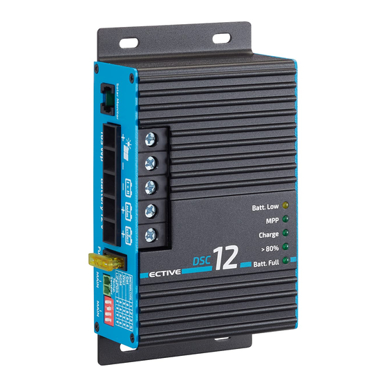
- Page 1 MPPT SOLAR CHARGE CONTROLLER MONTAGE- UND BEDIENUNGSANLEITUNG INSTALLATION AND OPERATING MANUAL • ECTIVE DSC 12 • ECTIVE DSC 25 • ECTIVE SC 20 • ECTIVE SC 40...
-
Page 2: Table Of Contents
Inhaltsverzeichnis Einführung Funktionsweise Sicherheitsrichtlinien und Zweckbestimmte Anwendung Anschluss-Schema Anschluss Hinweise zum Laden der Batterie Technische Daten Betriebsanzeigen APP Anzeige / Bluetooth Funktion Betriebshinweise ENGLISH VERSION... -
Page 3: Einführung
Herzlich Willkommen! Vielen Dank, dass Sie sich für einen ECTIVE MPPT-Solarladeregler entschieden haben! Bitte beachten Sie, dass diese Anleitung für die folgenden Modelle gilt: ECTIVE DSC 12 ECTIVE DSC 25 ECTIVE SC 20 ECTIVE SC 40 Abschnitte der Anleitung, die sich nur auf bestimmte Modelle beziehen, sind entsprechend gekennzeichnet. -
Page 4: Funktionsweise
Funktionsweise MPPT-Solarladeregler für hochwertige Reisemobile, Caravan und den Marinebereich. ECTIVE MPPT-Solarladeregler mit „IU1oU2“-Ladekennlinie werden als Bindeglied zwischen Solar-Panel(s) und Batterie(n) geschaltet. Bei der MPPT-Technologie ermittelt der Regler immerzu automatisch mehrmals pro Sekunde die maximale Leistungsausbeute (MPP) der Solar-Module. Er transformiert dann den Spannungsüberschuss des Solar-Moduls auf einen höheren Ladestrom für die Batterie um... - Page 5 Temperaturen. Unbedingt empfohlen, wenn die Batterietemperatur im laufenden Betrieb unter 0°C fallen kann. • Steckerfertig für den Anschluss von diversen Solar Monitoren, z.B. ECTIVE SM1 oder ECTIVE SM2. Nur für DSC 12, DSC 25: • Zwei Batterie-Ladeausgänge: Automatisches Laden Hauptversorgungs-Bord-Batterie (MAIN I) sowie Stützladung und...
-
Page 6: Sicherheitsrichtlinien Und Zweckbestimmte Anwendung
Sicherheitsrichtlinien und zweckbestimmte Anwendung Der MPPT-Solarladeregler wurde unter Zugrundelegung der gültigen Sicherheitsrichtlinien gebaut. Die Benutzung darf nur erfolgen: 1. Für das Laden von Blei-Gel/-AGM/-Säure-Batterien oder LiFePO4- Komplettbatterien (mit integriertem BMS, Balancing, Sicherheits- beschaltung und Zulassung!) der angegebenen Nennspannungen und die Mitversorgung von an diesen Batterien angeschlossenen Verbrauchern in fest installierten Systemen mit den angegebenen Batteriekapazitäten und Ladeprogrammen. - Page 7 Sicherheitsrichtlinien und zweckbestimmte Anwendung MPPT-Solarladeregler heranführen, damit im Fehlerfalle eindringende Feuchtigkeit nicht zum Regler gelangen und diesen beschädigen kann. • Niemals 12 V (24 V)-Kabel mit 230 V-Netzleitungen zusammen im gleichen Kabelkanal (Leerrohr) verlegen. • Spannungsführende Kabel oder Leitungen regelmäßig auf Isolations- fehler, Bruchstellen oder gelockerte Anschlüsse untersuchen.
-
Page 8: Anschluss-Schema
• Kabelquerschnitte und -längen lt. Anschluss-Schema und Tabelle einhalten! • Unbedingt auf die richtigen Polaritäten (+ und -) von Solar-Panel und Batterien achten! • Kabelschutz: Sicherungen nahe der Batterien in die + Leitungen einfügen (gegen Kabelbrandgefahr)! DSC 12 MPPT & DSC 25 MPPT Solar Monitor Batterietyp (optional) wählen... - Page 9 Anschluss-Schema Das Anschlussschema zeigt die maximale Anschlussbelegung zum Betrieb aller vorhandenen Funktionen des jeweiligen MPPT-Solarladeregler. Die minimale Anschlussbelegung besteht aus den Solarpaneleingängen („+“ und „-“) und den Anschlüssen zur Hauptbatterie. SC 20 MPPT & SC 40 MPPT Solar Monitor (optional) Temperatur- Sensor 12 V: max. 240 W 24 V: max. 480 W...
-
Page 10: Anschluss
Anschluss (Beachten Sie das Anschluss-Schema Ihres Modells!) 1. (Main) Batterie - muss angeschlossen werden Für DSC 12, DSC 25 Batterieanschlüsse des Reglers - (Minus) und + (Plus) mit der 12 V-Hauptbatterie polrichtig verbinden, Kabelquerschnitte einhalten (siehe Anschluss-Schema). Regler nicht ohne Batterie „MAIN I“ betreiben. Das Gerät gibt ohne angeschlossene Batterie keine definierte Ausgangsspannung ab. - Page 11 Strommessung des Gerätes verfälschen und darf nicht bestehen. 3a. Starterbatterie “Start II” (Optional) (!) Nur für DSC 12, DSC 25 Zweiten Ladeausgang mit rotem Anschlusskabel (Drahtquerschnitt 1,5-2,5 mm²) mit der Fahrzeug-Starterbatterie verbinden, dieses Kabel darf länger sein. Bei Nichtbenutzung wird diese Anschlussklemme freigelassen.
- Page 12 Anschluss (Beachten Sie das Anschluss-Schema Ihres Modells!) 4. Temperatur-Sensor (Optional) Anschluss für den externen Ective Temperatur-Sensor (nicht im Lieferumfang enthalten). • Messung der Batterietemperatur der MAIN-Versorgungs-Batterie „I“ für Batterie-Schutz und -Regelung. • Den Sensor an der Anschlussbuchse „Temp. Sensor“ anschließen. • Der Einbauort des Sensors darf nicht von Wärmequellen (Motorblock, Auspuff, Heizung o.ä.) beeinflusst werden! Blei-Säure-, Gel-, AGM-Batterien: Montage: Der Sensor muss guten Wärmekontakt zur Batterie- Innentemperatur haben und sollte daher am Minus- oder Plus-Pol der Batterie angeschraubt werden. Alternativ kann er auch auf der...
- Page 13 Sensorleitungen sowie fehlerhafte Messwerte werden vom MPPT-Solarladeregler erkannt. Er schaltet dann automatisch auf die üblichen, von den Batterieherstellern empfohlenen 20°C/25°C-Ladespannungen zurück. 5. Solar Monitor (Optional) Anschluss für diverse Solar Monitore, etwa ECTIVE SM1 oder ECTIVE möglichen Anzeige folgender Werte: Batteriespannung, Ladestrom, Ladeleistung, gespeicherte Kapazität...
-
Page 14: Hinweise Zum Laden Der Batterie
Bei Lithium-Eisenphosphat-Batterien ausschließlich Ausführungen integriertem (Batterie Management System) Schutzbeschaltung verwenden! Stellen Sie die DIP-Schalter an der Seite des Geräts gemäß folgender Übersicht für den verwendeten Batterietyp ein. DSC 12, DSC 25 SC 20, SC 40 ↓ ↑ ↓ ↓ ↓ ↓... -
Page 15: Technische Daten
Technische Daten DSC 12 DSC 25 SC 20 SC 40 Solarmodul-Leistung max. [Wp] 240/480 480/960 Solarmodul-Strom max. 10 A 21 A 20 A 20 A Solarmodul-Spannung max. 50 V 50 V 50 V 50 V Batterie-Nennspannung (DC) 12 V 12 V 12/24 V 12/24 V Ladestrom Batt. I / II max. 12 / 1 A 25,5 / 1 A 20 A 40 A Eigenverbrauch 4 mA 4 mA 4 mA 4 mA Überladeschutz Rückstromsperre (Nachtbetrieb) -
Page 16: Betriebsanzeigen
MAIN-Batterie I, Batterie möglichst bald aufladen! >80% Alle LEDs Blinken: Leuchtet: Die Batterie wurde Nur für DSC 12, DSC 25: fast vollständig geladen. Der Solarladeregler lädt nun mit Die Wahlschalter „MAIN-Battery“ konstantem Ladestrom. stehen in einer ungültigen Stellung, der Solar-Regler hat zur Sicherheit abgeschaltet. -
Page 17: App Anzeige / Bluetooth Funktion
Symbol zeigt an, dass das Gerät die App-Anzeige per Bluetooth unterstützt. 1. Laden Sie die App vom App Store (iOS) oder Google Play Store (Android) herunter. Alternativ finden Sie den Download auf ective.de. 2. Batterie und Solarpanel anschließen. 3. Bluetooth-Funktion auf dem Smartphone aktivieren. -
Page 18: Betriebshinweise
Betriebshinweise Batterielebensdauer: • Tiefentladene Batterien sofort aufladen: Sulfatierung Einsetzende Bleigitter Tiefentladungen durch baldige Ladung unterbinden, insbesondere bei hohen Umgebungstemperaturen. Falls die Sulfatierung noch nicht zu weit fortgeschritten war, kann die Batterie einen Teil der Kapazität nach einigen Lade-/Entladezyklen zurückerlangen. Tiefentladung darf bei LiFePO4-Batterien nicht vorkommen! •... - Page 19 Betriebshinweise • Überlast-/Überhitzungsschutz MPPT-Solarladeregler: Der MPPT-Solarladeregler ist gegen Überlastung doppelt elektronisch gesichert und schützt sich selbst gegen widrige Einbaubedingungen (z. B. schlechte Belüftung, zu hohe Umgebungstemperaturen) durch allmähliche Abregelung der Ladeleistung. • Spannungsmessungen: Die Spannungen an den Klemmen des MPPT-Solarladereglers können durch Ladekabelverluste an den Ladekabeln höher sein als an der Batterie.
- Page 20 Content Introduction Features and Functions Safety Information and Appropriate Application Connection Plan Connection Instructions for Battery Charging Technical Data LED Indicators APP Display / Bluetooth Functionality Operating Instructions...
-
Page 21: Introduction
Welcome! Thank you for choosing an ECTIVE MPPT Solar Charge Controller! This manual applies to the following devices: ECTIVE DSC 12 ECTIVE DSC 25 ECTIVE SC 20 ECTIVE SC 40 Sections in the manual which only apply to specific devices are marked accordingly. -
Page 22: Features And Functions
Features and Functions MPPT Solar Charge Controller for high-quality motor homes, caravans and marine applications. ECTIVE MPPT Solar Charge Controllers with „IU1oU2“ load characteristic are employed as a link between the solar panel(s) and one or more batteries. Using MPPT technology, the charge controller automatically determines the maximum power yield (MPP) of the solar panels several times per second. - Page 23 LiFePO4 Batteries: Battery protection in case of high temperatures and particularly in case of low temperatures. • Ready for connecting various solar display monitors, e.g. ECTIVE SM1 and ECTIVE SM2. Only DSC 12, DSC 25: •...
-
Page 24: Safety Information And Appropriate Application
Safety Information and Appropriate Application The solar controller has been designed according to the valid safety regulations. For appropriate application, only use the solar controller... 1..to charge lead-gel, lead-AGM, lead-acid or LiFePO4-complete- batteries (with integrated BMS, equalization charging of the cells/ balancing and approval!) of the indicated nominal voltage and si- multaneous supply of the consumers connected to these batteries in fixed installed systems. - Page 25 Safety Information and Appropriate Application • Never lay 12 V (24 V) cables and 230 V mains supply cables into the same cable conduit (empty conduit). • Check live cables or leads periodically for insulation faults, breakage or loosened connections. Any defects must be remedied immediately. The unit is to be disconnected from any connection prior to execution of electrically welding or work on the electric system.
-
Page 26: Connection Plan
• It is imperative that the correct polarities ( + and - ) of solar panel and batteries are observed! • Cable protection: Insert the fuses near the batteries into the + cables (protection against cable fire)! DSC 12 MPPT & DSC 25 MPPT Solar Monitor (optional) Set battery... - Page 27 Connection Plan The connection plans show the maximum terminal assignment for operation of all existing functions of the solar controller. The minimum terminal assignment consists of the solar panel inputs (“+” and “-”) and the connections to the main battery. SC 20 MPPT &...
-
Page 28: Connection
Connection (Please consult the connection plan for your device!) 1. „MAIN I“ Battery (must be connected) Only DSC 12, DSC 25 Connect the battery connections of the controller - (minus) and + (plus) to the 12 V main battery, observing the correct polarity and the cross-section of the cables (refer to the connection plan). Never operate the controller without the battery „MAIN I“. - Page 29 3a. Starter Battery „Start II“ (Optional) (!) Only DSC 12, DSC 25 Connect the second charging port to the vehicle’s starter battery using the red connection cable (wire cross-section 1.5-2.5 mm². This cable may be longer.
- Page 30 12.80 V, for battery protection and the maximum charging current rate will be halved and safety mode, LED „MPP“ is flashing (DSC 12: „Charge“). Any charging data being recorded will be kept in memory. Battery charging is then interrupted but the supply of connected consumers will be continued by the solar controller, and the battery is allowed to cool down.
- Page 31 12.80 V, for battery protection, and the maximum charging current rate will be halved. Safety mode, LED „MPP“ is flashing (DSC 12: „Charge“). Any charging data being recorded hitherto will be kept in memory. Battery charging is then interrupted but the supply of consumers being possibly connected will be continued by the solar controller until the battery temperature is in the admissible range.
-
Page 32: Instructions For Battery Charging
BMS (battery management system) and safety circuit! Set the DIP switches on the side of your device to the correct battery type in accordance with the following tables: DSC 12, DSC 25 SC 20, SC 40 ↓ ↑... -
Page 33: Technical Data
Technical Data DSC 12 DSC 25 SC 20 SC 40 max. Solar Module Capacity [Wp] 240/480 480/960 max. Solar Module Current 10 A 21 A 20 A 20 A max. Solar Module Voltage 50 V 50 V 50 V 50 V Battery Nominal Voltage (DC) 12 V 12 V 12/24 V 12/24 V max. Charging Current Batt. I / II 12 / 1 A 25,5 / 1 A 20 A 40 A Stand-by Current Consumption 4 mA 4 mA 4 mA 4 mA Overcharge Protection Back Discharge Protection (Night... -
Page 34: Led Indicators
MAIN-I. Charge battery as soon as possible! >80% All LEDs flash: Lit: Battery almost fully charged. Only DSC 12, DSC 25: The solar charge controller is charging with constant charging The switches for „MAIN-I“ are current. configured incorrectly. As a precaution, the solar charge controller has deactivated itself. -
Page 35: App Display / Bluetooth Functionality
1. Download the app from the App Store (iOS) or Google Play Store (Android) or visit ective.de. 2. Connect battery and solar panels. 3. Activate the Bluetooth function on your smartphone. -
Page 36: Operating Instructions
Operating Instructions Lifetime of the battery: • Recharge deeply discharged batteries immediately: Incipient Sulphation of the lead battery plates due to deep discharge is to be prevented by charging soon, particularly in case of high ambient temperatures. If the grade of sulphation is not too intensive, the battery can recover part of the battery capacity after several charging/discharging cycles. - Page 37 Operating Instructions • Overload / Overheating Protection Solar Controller: The solar controller is equipped with a double electronic protection against overload and with an automatic protection against adverse installation conditions (e. g. insufficient ventilation, excessive ambient temperatures) by gradual reduction of the charging capacity. •...
- Page 39 ECTIVE.DE batterium GmbH Robert-Bosch-Str. 1 71691 Freiberg am Neckar Germany...
-
Page 40: Ective Sc
MPPT SOLAR CHARGE CONTROLLER • ECTIVE DSC 12 • ECTIVE DSC 25 • ECTIVE SC 20 • ECTIVE SC 40...
Need help?
Do you have a question about the DSC 12 and is the answer not in the manual?
Questions and answers