
Related Manuals for Wiedenmann Terra Spike SL 6

Summary of Contents for Wiedenmann Terra Spike SL 6
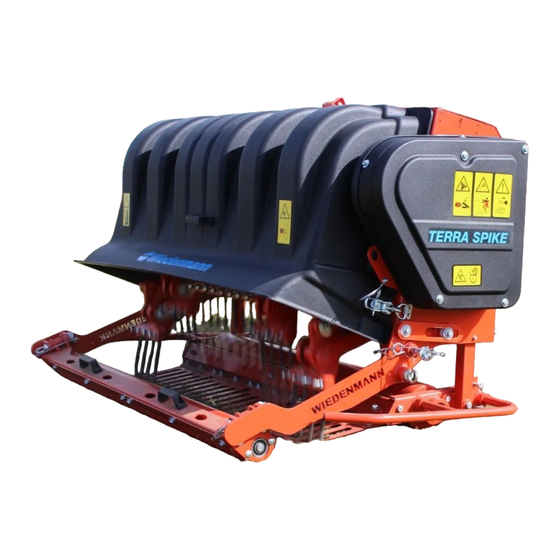
- Page 1 Translation of original operating instructions Deep Aerator Terra Spike SL 6 870.000 From machine ID no. : Version : June 2015 870 99 09...
- Page 2 All information, illustrations and specifications in this manual are based on the latest information available at the time of publication. We reserve the right to make changes at any time without notice.
- Page 3 All information, illustrations and specifications in this manual are based on the latest information available at the time of publication. We reserve the right to make changes at any time without notice.
- Page 4 Introduction PLEASE READ THESE OPERATION INSTRUCTIONS CAREFULLY in order to familiarize yourself the correct method of operation and maintenance and in order to avoid personal injuries or damage to the machine. This manual and safety decals on your machine may also be available in other languages (see your dealer to order).
-
Page 5: Table Of Contents
C O N T E N T S Page * * * * * * * * * * * * * * * * * * * * * * * * * * * * * * * * * * * * * * * * * * * * * * * * * * * 1.0. -
Page 6: Safety
1.0. Safety Measures RECOGNIZE SAFETY INFORMATION This is the safety alert symbol. When you see this symbol on your machine or in this manual, be aware of the potential for personal injury. Please observe all safety instructions and the general accident prevention regulations. - Page 7 1.0. Safety Measures OBSERVING ROAD TRAFFIC REGULATIONS Always observe local road traffic regulations when using public roads. WEAR PROTECTIVE CLOTHING Wear tight-fitting clothing and appropriate protective equipment when working with the machine. Prolonged exposure to loud noise can cause impairment or loss of hearing. Wear a suitable hearing protective device such as earplugs to protect against objectionable or uncomfortably loud noises.
- Page 8 1.0. Safety Measures STAY CLEAR OF ROTATING DRIVE SHAFTS Inattentiveness in the area of rotating drive shafts can have serious, or even fatal, consequences. Keep all drive shaft guards in place at all times. Make sure rotating shields can turn freely.
- Page 9 1.0. Safety Measures USE SAFETY LIGHTS AND DEVICES Avoid collisions with other road users. Slow moving tractors with attachments or towed equipment and machines are a particular hazard on public roads. Frequently check for traffic from the rear, especially in turns, Use hand signals or turn signal lights for safe operation in traffic.
- Page 10 1.0. Safety Measures Remove paint before welding or heating Welding must be conducted only by persons with appropriate qualifications. Avoid potentially toxic fumes and dust. Hazardous fumes can be generated when paint is heated by welding, soldering, or using a torch. Do all work outside or in a well ventilated area.
-
Page 11: Safety Decals
1.0. Safety Measures 1.1. Safety Decals Pictorial warning signs Warning signs are attached to several important places on this machine to indicate potential danger. The hazard is identified by an exclamation point in a warning triangle. An adjacent symbol shows information on how to avoid personal injury. - Page 12 1.0. Safety Measures 1.1. Safety Decals Parking position Before parking fix rear roller with ring pins and secure it. 870.03 Tines Never touch moving parts of the machine. Wait until they have come to a complete standstill. 870.04 All information, illustrations and specifications in this manual are based on the latest information available at the time of publication.
- Page 13 1.0. Safety Measures 1.1. Safety Decals Tines Be careful to avoid injury to foot. 870.05 Service Before performing service or repair work, turn off engine and remove key. 870.06 Operation Do not climb onto the machine while the engine is running. RISK OF FALLING ! 870.07 423.07...
-
Page 14: Safety Equipment
1.0. Safety Measures 1.2. Die Sicherheits-Einrichtungen ALLGEMEINE ANFORDERUNGEN ZUR SICHERHEITSKENNZEICHNUNG Eine Sicherheitskennzeichnung mit folgenden Sicherheitspraktiken oder ähnlichen Mitteilungen soll an der Maschine angebracht werden. Das Label soll möglichst von der Arbeitsposition aus sichtbar sein. a) Lesen Sie die Bedienungsanleitung. b) Die Maschine nicht ohne Schutz, Schutzschilder und richtig platzierte und funktionsfähige Sicherheitsvorrichtungen betreiben. -
Page 15: Safety Instructions
1.0. Safety Measures 1.3. Safety instructions Besides the information in Always ensure there is these operating sufficient front-axle instructions, please also load; the steering observe all generally capability of the vehicle applicable safety and must be maintained. accident-prevention ... -
Page 16: Assembly
2.0. Assembly 2.1. General Check whether all connection parts necessary for complete delivery are there. Attach and remove the machine on flat, solid ground only. For this work, please use your personal protective equipment (PSA) such as: gloves, goggles, ear protectors. ATTENTION DANGER : Be careful when cutting through the tension straps. - Page 17 2.0. Assembly 2.2. Unpacking and setting up the Terra Spike 4. The hex bolt (D) and the intermediate piece (E) must be removed on both sides of the Terra Spike. These parts have been installed only for shipping. 5. Raise the Terra Spike until the pin (F) can be inserted in the rear hole (G) in order to secure the rear roller.
- Page 18 2.0. Assembly 2.3. Installing the swather CAUTION! Only carry out conversion work when mounted. Lower the Terra Spike on the fully lowered front roller. Switch off the tractor and secure it against unintentional starting. To remove the roller and to attach the swather, raise the rear roller (see Chapter 6.6.).
- Page 19 2.0. Assembly 2.3. Mounting the swather Park the swather behind the Terra Spike. With one hand, grasp the transverse frame of the swather and lift between the arm brackets. With the other hand, push the pin (C) through the brackets and the bearing bushing to secure.
-
Page 20: Transport
3.0. Transport 3.1. General ATTENTION DANGER: ° TERRA SPIKE is delivered fastened to a pallet. ° Only use a forklift with sufficient load-carrying capacity. ° Keep well clear of hoisted loads. If the load falls it may cause fatal injuries. Improper transport and mounting of TERRA SPIKE may cause: ... -
Page 21: Transporting The Terra Spike
Unload the TERRA SPIKE when it is securely suspended. NOTE : Inform the transport company and Wiedenmann GmbH or the supplier immediately in writing about shipping damage or missing parts. All information, illustrations and specifications in this manual are based on the latest information... - Page 22 3.0. Transport 3.2. Transporting the TERRA SPIKE Hitching point for transport on 3.2.3. a trailer ATTENTION DANGER: Note the description of removal in Section 5.2. - RISK OF TIPPING OVER! Tighten the belts evenly at diagonally opposite points. Attachment points for belts on the front of the Terra Spike Attachment points for belts on the back of the Terra Spike...
-
Page 23: Connecting To The Tractor
4.0. Attachment to tractor 4.1. General Always pay attention to: The load on the three point hitch. Only attach the TERRA SPIKE if the following is true: the engine turned off the PTO shaft disengaged with the rear roller fixed. Use the TERRA SPIKE only with: ... -
Page 24: Attaching The Terra Spike To A Tractor
4.0. Attachment to tractor 4.2. Attachment to the tractor Prerequisite for connecting: a three-point hitch. NOTE : ° note the bending angle of the PTO shaft. Mounting steps: 1. Pin and secure the lower link with the pins (A) in the correct hole pattern on the frame. -
Page 25: Adjusting The Pto Shaft
4.0. Attachment to tractor 4.3. Adjusting the pto shaft To adjust the length hold the two shaft parts side by side within the shortest operating position and mark them. Cut off the inner and outer sliding profile to the same length as the sheath. -
Page 26: Detaching From Tractor
ACHTUNG: Always place the machine on a firm and smooth surface to disconnect it. Secure the TERRA Spike SL 6 to prevent it from rolling away. Only remove the TERRA SPIKE the engine turned off, the PTO shaft disengaged, ... -
Page 27: Parking Terra Spike With Rear Roller
5.0. Removal from tractor 5.2. Before parking Pin and secure the support (K) in the lowermost position. 5.3. Parking TERRA SPIKE with rear roller Sequence: 1. Park the towing vehicle. 2. Set the parking brake to secure the tractor against rolling away. -
Page 28: Before Using
6.0. Before Using 6.1. General ATTENTION It is important to become familiar with all devices and operating elements as well as their action before starting service to make sure that all safety equipment has been properly mounted. It will be too late for this during operation! Make sure that no one is in the... -
Page 29: Indicator And Adjustment Components
6.0. Before Using 6.2. Indicator and adjustment components Crank (A) for adjusting the working depth (raising or lowering the roller). Scale (B) for the tool length Depth scale (C) for reading off the set working depth Ruler (D) and pointer (E) Spindle (F) for setting the plunging angle The setting is carried out... -
Page 30: Mounting The Tines
6.0. Before Using 6. 3. Mounting the tines NOTE When mounting the tines: 1. Lift the TERRA SPIKE with tractor hydraulics. 2. Lower front roller to bottom position. 3. Lower the TERRA SPIKE on front roller. 4. Shift the tine holder you are working with upwards (by pressing an upper tine holder). - Page 31 6.0. Before Using 6. 3.1. Mounting tines in cylindrical holders: 1. Remove the protective cap (A) from the tool head (B). 2. Loosen nut (C). 3. Place 1/2“ tine (E) or 5/16“ tine (F) with bushing (G) as shown in illustration. 4.
-
Page 32: Adjusting The Terra Spike
6.0. Before Using 6.4. Adjusting the TERRA SPIKE NOTE Always make adjustments when the device has been attached and in lifted position. On delivery of the TERRA SPIKE the angle of insertion is set to zero position. Each time the device is adjusted, tine length “A“... -
Page 33: Installing Drive
6.0. Before Using 6.4. Adjusting the TERRA SPIKE 3)Set the TERRA SPIKE upright by doing the following: ● Loosen the lock nut (J) for the upper link ● Adjust using the upper link(H) 4)The setting can be checked with a bubble level (K) on a horizontal surface. - Page 34 6.0. Before Using 6.5. Adjusting the angular position 5. Attach a ratchet (C) with a matching socket (D) to the spindle (E). Adjust by turning: clockwise for 0 to 18 counterclockwise for 18 to 0 6. The setting can be read off on the indicator (F) 7.
-
Page 35: Raising The Rear Roller
6.0. Before Using 6.6. Raising the rear roller NOTE : The rear roller is a safety feature and must not be removed. By being raised, the rear roller acts as hoop guard for the danger zone behind the working tools. -
Page 36: Operation
7.0. Operation 7.1. General ATTENTION ! The operator of the TERRA SPIKE is responsible for persons inside the working area. Never operate the TERRA SPIKE without its safety devices. If you do operate the TERRA SPIKE without safety devices, you expose yourself and others to extreme danger. -
Page 37: Faults And Remedies
7.0. Operation 7.3. Faults and remedies Description Cause Remedy The power takeoff shaft speed Reduce the power takeoff is too high at a shallow shaft speed working depth. The tines are too long Check tine lengths The guide roller arms have too Secure with side locking much play screws... -
Page 38: Faults And Remedies
7.0. Operation 7.3. Faults and remedies Description Cause Remedy The tines cannot be mounted Clean locating bores The locating holes for the tines are dirty Seal unused locating holes (see Chapter 6.3.) Readjust the shedder The trailing roller is no longer The shedder is pressing on the (see Chapter 7.4.) turning... -
Page 39: Setting Scraper
7.0. Operation 7.4. Setting scraper Adjust the 2-part scrapers on the front roller and the rear roller to prevent debris from adhering to the rollers. Set the scraper blade approx. 0.04 in. from the roller. Front roller Loosen hex nuts (A). In the attached recesses, the scrapers are to be pushed with a screwdriver into the desired... -
Page 40: Service
Only perform maintenance work guarantee claims can only be when the TERRA SPIKE is recognized, if original parts mounted. Switch off from Wiedenmann have been the tractor and secure it used exclusively. against unintentional We would like to draw your starting. -
Page 41: Maintenance And Inspection List
8.0. Service 8.2. Maintenance and inspection list Working Check Procedure hours 1 after initial the position of the tines to each other the position of the tines to each other is set with the buffers. Tines are firmly mounted Check Bolts and screws are firmly secured Tighten screws if necessary Rubber-metal rails... -
Page 42: Lubrication
8.0. Service 8.3. Lubrication Switch off machine before all lubrication work. Clean lubrication nipple before use. Clean up leaking grease. Before starting the machine after a longer standstill, lubricate and maintain the entire machine. Lubricate frequently as required. -
Page 43: Cleaning The Terra Spike
8.0. Service 8.4. Cleaning the TERRA SPIKE Clean the TERRA SPIKE regularly. You will prolong the service life of expensive components and simultaneously detect: Loose components Wear and unintended collision points. NOTE: Do not bring plastic and sealing elements in contact with aggressive liquids (e.g. -
Page 44: Locking Safety Cover
8.0. Service 8.5. Locking safety cover The cover must be locked in an open position to prevent it from falling during all work that requires it to be open. To lock it as shown in the picture insert the spring clips into the cover. - Page 45 8.0. Service 8.6. Checking or replacing rubber parts Remove hex screws (A) and place the swing lever (B) down. To remove the defective metal rail (C), the hex bolts on the back (D) must be loosened. NOTE: For the installation, we recommend replacing the Nord-Lock locking washers.
-
Page 46: Changing Tines
8.0. Service 8.7. Changing tines ATTENTION ! Only perform maintenance work when the TERRA SPIKE is mounted. Switch off the tractor and secure it against unintentional starting. There is a risk of injury due to the tine tip. 1. Place tine holder that is being worked on in up position (by pressing on an upright tine holder). -
Page 47: Replacing The Tool Head
8.0. Service 8.8. Replacing the tool head ATTENTION ! Only perform maintenance work when the TERRA SPIKE is mounted. Switch off the tractor and secure it against unintentional starting. There is a risk of injury due to the tine tip. 1. -
Page 48: Checking And Tensioning Power Transmission Belt
8.0. Service 8.9. Checking and tensioning power transmission belt ATTENTION ! Only perform maintenance work when the TERRA SPIKE is mounted. Switch off the tractor and secure it against unintentional starting. The individual steps are described in Chapter 8.10. on Page 49. -
Page 49: Changing Drive Belt
8.0. Service 8.10. Changing drive belt ATTENTION ! Only perform maintenance work when the TERRA SPIKE is mounted. Switch off the tractor and secure it against unintentional starting. 1. Remove the side guard (A) by uniformly loosening the hex bolts. 2. - Page 50 8.0. Service 8.10. Changing drive belt 10. Install the drive belt (K). 11. Fit the V-belt pulley (L) into the drive belt. 12. Push the tapered tensioning bushing (N) (of the V-belt pulley) onto the shaft (M). 13. Align the spring bushing (N) with the securing holes of the V-belt pulley.
-
Page 51: Service
8.0. Service 8.10. Changing drive belt 18. Turn the hex nut (F) approx. 20 mm upwards. 19. Turn the hex nut (E) down a distance "X" = 70 mm (2.76 in.) 20. Check the belt tension as specified in Chapter 8.9. 21. -
Page 52: Adjusting The Angular Position
8.0. Service 8.11. Installing drive ATTENTION ! Only perform maintenance work when the TERRA SPIKE is mounted. Switch off the tractor and secure it against unintentional starting. 1. Remove the side guard (A) by uniformly loosening the hex bolts. 2. The tensioner pulley lever with tensioner pulley (B) must be completely relieved of tension for the removal... - Page 53 8.0. Service 8.11. Installing drive 10. Install the drive belt (K). 11. Fit the V-belt pulley (L) into the drive belt. 12. Push the tapered tensioning bushing (N) (of the V-belt pulley) onto the shaft (M). Align the spring bushing (N) with the securing holes of the V-belt pulley.
- Page 54 8.0. Service 8.11. Installing drive 18. Turn the hex nut (F) approx. 20 mm upwards. 19. Turn the hex nut (E) down a distance "X" = 70 mm (2.76 in.) 20. Check the belt tension as specified in Chapter 8.9. 21.
- Page 55 8.0. Service 8.12. Replacing the rubber part for angle adjustment Carry out this work only when Switch off the tractor and the machine is attached. secure it against unintentional starting. Lower the Terra Spike on the fully lowered front roller. Pin and secure the rear roller in the park position (see Chapter 5.2.).
-
Page 56: For The Downholder Carrier
8.0. Service 8.12. Replacing the rubber part for angle adjustment Lock the setting in place using the nut (C). The final position of the spindle (K) is determined by the flap (B), which is pivoted upwards to lock in the setting. Attach the folding plug (A) on the spindle (K). -
Page 57: Disassembly / Disposal
8.0. Service 8.14. Disassembly / Disposal ATTENTION ! Take care when you disassemble the TERRA SPIKE. Read the chapter "Safety and Precautions" and observe local safety regulations. The following dangers exist: Heavy parts might fall down after dismounting, Sharp edges, The machine might tilt and crush someone. -
Page 58: Unauthorized Modification And Spare Part Manufacturing
8.0. Service 8.15. Unauthorized modification and spare part manufacturing Modifications of the TERRA SPIKE are only authorized with the permission of the manufacturer! Original spare parts and accessories authorized by the manufacturer guarantee your safety. The use of other parts might change the characteristics of the TERRA SPIKE. -
Page 59: Equipment
9.0. Equipment 9.1. Equipment supplied Terra Spike SL 6 in shipping frame on shipping floor with drive for crankshaft speeds of 280 rpm 360 rpm 460 rpm Cardan shaft Operating manual, transfer declaration with warranty card. 9.2. Optional equipment Downholder set made of steel with (2.17 in.) partitions... - Page 60 10.0. Specifications 10.1. Technical details Height to lower connecting rod connection, bottom 15 in. 390 mm Height to lower connecting rod connection, top 19 in. 490 mm Height up to middle of connection of upper guide rod 36 in. 915 mm Height up to connection 23 in.
- Page 61 10.0. Specifications 10.1. Technical details 870.68 All information, illustrations and specifications in this manual are based on the latest information available at the time of publication. We reserve the right to make changes at any time without notice.
- Page 62 10.0. Specification 10.2. Metric bolt and cap screw torque values Property Class and Head Markings Property Class and Markings class 4.8 class 8.8 or 9.8 class 10.9 class 12.9 Dry ** Lubricated * Dry ** Lubricated * Dry ** Lubricated * Dry ** Lubricated * Size...
-
Page 63: Specifications
10.0 Specifications 10.3. Serial Number Record product identification No. (serial no.) in the space Wiedenmann D-89192 Rammingen provided below. Always quote Baujahr Fz. Id. Nr. Zul. Ges.Gew. Zul.Achsl.vorn Zul.Achsl.hi. this number when ordering- spare parts or in case of- warranty claims.
Need help?
Do you have a question about the Terra Spike SL 6 and is the answer not in the manual?
Questions and answers