Paul CLIMOS F 200 Eco Operating Instructions Manual
Mechanical ventilation heat recovery unit
Hide thumbs
Also See for CLIMOS F 200 Eco:
Table of Contents
Advertisement
Advertisement
Table of Contents

Subscribe to Our Youtube Channel
Related Manuals for Paul CLIMOS F 200 Eco


Summary of Contents for Paul CLIMOS F 200 Eco
- Page 1 Version: 1.1_08/2019...
- Page 2 The information contained in these documents is the property of PAUL Wärmerückgewinnung GmbH. The publication, whether partially or completely, requires the written consent of PAUL Wärmerückgewinnung GmbH. Any in-house reproduction intended to evaluate the product or for proper use is permitted and is not subject to approval.
-
Page 3: Table Of Contents
Index Preamble ..........................5 Validity ............................5 Target group and standard operation ..................5 Qualification of target group ..................... 5 0.2.1.1 Users ............................5 0.2.1.2 Qualified personnel ........................5 Standard operation of the unit ....................5 Introduction and safety ......................5 Proper use .......................... - Page 4 3.3.1.2 Connecting of the connection cable to the control unit ............19 Connection of external boost ventilation switch ..............23 Connection of external sensors ..................... 23 Commissioning of the CLIMOS ....................23 Operational readiness ......................23 Adjusting the air volume flow ....................23 Adjustment of the Valves .......................
-
Page 5: Preamble
• CLIMOS F 200 Eco – Serie (Zehnder Climos 200 Enthalpie Eco – Serie) The types of device CLIMOS F 200 Eco, are hereinafter referred to under the product name CLIMOS, unless details are for type differentiation. The subject of this manual is the CLIMOS in its various design variants. Possible accessories are only described to the extent necessary for appropriate operation of the unit. -
Page 6: Safety
Safety Always observe the safety regulations and installation conditions in the current operating manual. Failure to observe the safety regulations, installation conditions, instructions, warnings, and comments in this document can result in personal injury or damage to the unit. Safety regulations •... -
Page 7: Liability
Liability The CLIMOS was developed and manufactured for use in so-called comfort ventilation systems. Any other use is considered as “improper use” and can result in damages to the CLIMOS or in personal injuries, for which the manufacturer cannot be made liable. The manufacturer is not liable for any damage, which is due to the following causes: •... -
Page 8: Type Plate
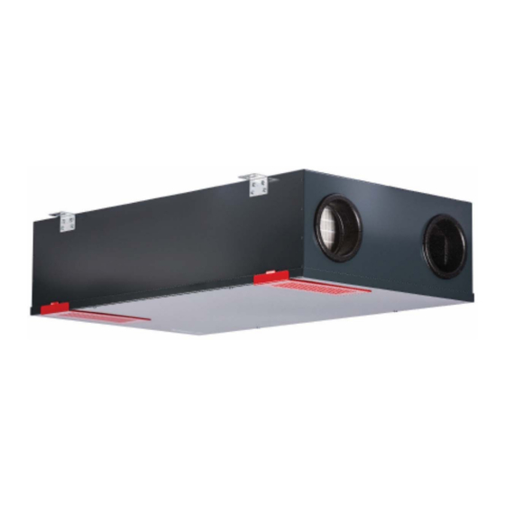
Fig 1: Main components CLIMOS Item Designation Casing cover with quarter turn lock (4x) EPP filter cover (2x) Filter (2x) Retaining clamps (4x) Mounting bracket (4x) Design filter cover (2x), Option Heat exchanger box Control unit Fan box (2x) Housing Tab. -
Page 9: Joint Operation With Heat-Producing Appliances
Joint operation with heat-producing appliances In case of simultaneous operation with heat-producing appliances, e.g. chimneys, the corresponding standards and regulations must be complied with by the qualified personnel. The joint operation of indoor air-dependant heat- producing appliances and ventilation plants requires an appropriate safety device (differential pressure switch) or a plant-specific measure, in the event that dangerous negative pressures can be generated in the installation room of the heat-producing appliance during operation. -
Page 10: Signalling Of Operating And Maintenance Modes
Push button supply air The supply air mode and the supply air fan are switched on by pushing and locking. mode By pushing again the supply air mode is deactivated again. Normal-mode Both fans are switched on by pushing and locking. Button boost ventilation Function-button for boost ventilation mode: mode / reset filter runtime... -
Page 11: Maintenance By The Operator
Maintenance by the operator Maintenance of the ventilation device and plant by the operator is limited to the periodic change of the filters and cleaning of the supply and extract air valves. The filter must be checked every 3 months and changed if necessary, however, at least every 6 months. - Page 12 4. Remove the EPP filter cover C. Fig 5: Removal of the EPP filter cover 5. Pull the filter D out of the filter compartment by holding it on the strap. Fig 6: Removal of the filter 6. Insert the new filter. The arrow E on the filter frame and the arrow F impressed into the EPP filter compartment (next to the recessed grip) must point in the same direction! Fig 7: Insertion of the new filter...
-
Page 13: Reset Of Filter Runtime
Disposal When the life time cycle of your CLIMOS has expired, the company PAUL Wärmerückgewinnung GmbH offers you free take-back. If you do not make use of the possibility of feedback of recyclable product parts into the cycle of materials, we would like to remind you that the CLIMOS must not be disposed of in the normal household garbage. -
Page 14: Mounting Preparations
Fig 8: Distances in mm to adjacent surfaces For the CLIMOS the following mounting positions are possible: • ceiling-hanging or lying (horizontally) • wall-mounted (horizontally or vertically) • inclined wall (horizontally or vertically) The exhaust air connection must always be located at the top! Mounting Preparations At first, mount at the long sides of the CLIMOS 2 pieces of the provided mounting brackets each with 4 cross-head screw each. -
Page 15: Mounting Position Lying
of the drywall inspection flap is at least 270 mm. In this case, the ventilation device is fixed centrically in the opening space of this maintenance flap at the raw ceiling. Fig 10: Mounting position ceiling-hanging Mounting position lying In case of the mounting position lying, the mounting is made horizontally on the ground surface in the slotted holes (38x10 mm) of the 4 mounting brackets with suitable fixing elements depending on the ceiling construction. -
Page 16: Mounting Position Inclined Wall Horizontally
Fig 13: Mounting position wall-mounted vertically Mounting position inclined wall horizontally In case of the mounting position inclined wall horizontally the mounting is made horizontally at the inclined wall surface in the slotted holes (38x10 mm) of the 4 mounting brackets with suitable fixing elements depending on the wall construction. -
Page 17: Air Duct Connection
Fig 15: Mounting position inclined wall vertically Air duct connection When mounting the air ducts, the following points must be taken into account: • Mount the types of air ducts of the ventilation plant to the connection stubs according to the present construction form R (right - type A) or L (left - type B), see label air ducts next to the type plate. -
Page 18: Electrical Connections
Fig 18: Casing side of the electrical connections Position Designation 3-pole IEC connector Pre-cut cable bushing (2x) for cable gland M16 Circuit diagram CLIMOS F 200 Eco Comfort 3.7.4 Tab. 4: Assignment of the electrical connections Connection control panel 3.3.1.1 Connecting of the connection cable to the control panel The external operating panel is installed in a standardised switch box. -
Page 19: Connecting Of The Connection Cable To The Control Unit
3.3.1.2 Connecting of the connection cable to the control unit Proceed as follows in order to connect the connection cable to the control board: 1. Disconnect the CLIMOS from the power supply. 2. If applicable, pull the red design filter covers A out of the casing cover’s holder. Fig 19: Pull out 2x design filter covers 3. - Page 20 4. Remove the casing cover C and remove the cable for potential equalisation from the flat plug of the casing cover. Fig 22: Remove the casing cover C from the device 5. Loosen the 2 locking screws D of the control system casing by approx. 4 - 6 mm by turning them counter clockwise and remove the cable for potential equalisation from the flat plug of the control system casing.
- Page 21 7. Withdraw the control system casing step by step as indicated by the arrows. Fig 25: Removal of the control system casing in direction heat exchanger Fig 26: Removal of the control system casing above 8. Guide the cable through one of the two rubberised grommets F of the control system casing. Fig 27: 2x cable grommet F at the control system casing...
- Page 22 9. Connect it to the terminal points provided for that purpose according to Tab. 6. Fig 28: control system casing with control board G Terminal X0 control board Signal X0.01 +12 V X0.02 (control voltage supply air fan) X0.03 (control voltage exhaust air fan) X0.04 Tab.
-
Page 23: Connection Of External Boost Ventilation Switch
Fig 30: Locking of the control system casing 13. Connect the cables for potential equalisation to the respective flat plugs of the casing parts. 14. Close the casing cover by turning the 4 captive screws of the quarter turn locks B by 90°. 15. -
Page 24: Adjustment Of The Valves
Fig 31: Chart 1, Parameterizing fan speed Fig 32: Chart 2, Assignment volume flow ranges Adjustment of the Valves Make sure that the supply and extract air valves are open as much as possible at the beginning of the volume flow measurement. •... -
Page 25: Inspecting And Cleaning The Heat Exchanger
cleaning of the fans and the heat exchanger. Cleaning of the heat exchanger is carried out depending on the degree of soiling; the maintenance interval should not exceed two years. The maintenance work performed must be documented in check list B! Inspecting and cleaning the heat exchanger In order to do so, proceed as follows: 1. - Page 26 4. Remove the casing cover C and remove the cable for potential equalisation from the flat plug of the casing cover. Fig 36: Remove the casing cover C from the device 5. Pull the retaining clamps D (4x) out of the EPP foam modules in vertical position. Fig 37: Retaining clamps D for form-fit fastening of the EPP foam modules 6.
- Page 27 Fig 38: Unlocking of the heat exchanger box G by shifting the fan boxes F In the event that the fan boxes F cannot be shifted, the air duct connection stubs of the fan boxes F must be shortened! Cut through the EPP connection stubs in the circumferential groove H (set point of sectioning) Fig 39: Shortening of the EPP connection stub at the set point of sectioning of the circumferential groove H After having finished the maintenance work, all disconnected air ducts must be reconnected to the heat recovery unit in air-tight condition.
- Page 28 Fig 40: Removal of the heat exchanger box G 8. Clean internal heat exchanger heat exchanger necessary. Fig 41: Heat exchanger I in the heat exchanger box G In order to do so, proceed as follows: • Dip the heat exchanger into warm water several times (max. 40 °C). •...
-
Page 29: Visualising Of Operating Modes
Fig 42: Outdoor casing fan box J (2x) 10. After inspection, mount all parts in reverse order. When installing the heat exchanger box, ensure correct locking with the fan boxes by means of the tongue-and-groove joint! Fig 43: Push direction of the fan boxes for locking with the heat exchanger box Connect the cable for potential equalisation to the flat plug of the casing cover. -
Page 30: Technical Desciption
Technical desciption Designs layout air connection Design R (right - type A) Design L (left - type B) Tab. 10: Overview types of designs R (right - type A) and design L (left - type B) Technical specification General specification Description / value Type of heat exchanger Enthalpy exchanger with polymer membrane... - Page 31 p- -characteristic curve Please note: The numerical values of the p- -characteristic curve which are illustrated in the chart indicate the power consumption in [W] in the respective operating points without activated preheater. Tab. 13: Chart 3, p- characteristic curve...
-
Page 32: Dimensional Sketch
Dimensional sketch Fig 44: Dimension drawing... -
Page 33: Circiut Diagram Climos Eco - Series
Circiut diagram CLIMOS Eco - series Fig 45: Terminal assignment CLIMOS Eco... -
Page 34: Annexes
Annexes Checklist A maintenance works user Enter date for the quarter Maintenance works 1. Change both the filters in the device (Filter change cycle 90 days) Quarter Year 20... 20... 20... 20... 20... 20... 20... 20... 20... 20... 2. Clean extract air prefilter / filter in extract air valves (change approx. every 2 months) Quarter Year 20... -
Page 35: Checklist B Maintenance Works Qualified Personnel
Checklist B maintenance works qualified personnel Enter Result Maintenance works − Inspection of MVHR unit based according to the currently valid national standards − Informal report for comments on MVHR unit's condition − Use additional sheet of paper for adding reports of subsequent years Parts Annually Result... -
Page 36: Commissioning And Handover Certificate
Commissioning and handover certificate Customer data Name: First Name: Tel: Street: Postal Code: City: Construction Projects: Type of device: Serial number: Year of manufacture: Completeness Parts Design Result - Design as planned yes / no Supply air duct - There is an option to clean yes / no - Layout as planned yes / no... -
Page 37: Air Volume Log
Air volume log Customer data Name: First name: Tel: Street: Postcode: City: Construction Projects: Type of device: Serial number: Year of manufacture: Measurement data Used measuring device: Description of failures during Internal temperature: the measurement: External temperature: Filer status during calibration Outdoor Exhaust air State of building Fan speed ratio... -
Page 38: Product Fiche
Product fiche... -
Page 39: Product Label
Product label For the CLIMOS, there are two different product labels, depending on the application of the device. The product label, which applies for the ventilation plant, conforms to the installation of the plant and to the model identifier of the product data sheet. -
Page 40: Conformity
Product Description: Heat Recovery Unit CLIMOS F 200 Eco - series Directive 2014/35/EU of the European Parliament and of the Council of 26 February 2014 on the harmonisation of the laws of the Member States relating to the making available on the market of electrical equipment designed for use... - Page 41 PAUL Wärmerückgewinnung GmbH August-Horch-Str. 7 08141 Reinsdorf Germany Tel: +49 (0) 375 - 30 35 05 0 Fax: +49 (0) 375 - 30 35 05 55 info@paul-lueftung.de www.paul-lueftung.de Version: 1.1_08/2019...
Need help?
Do you have a question about the CLIMOS F 200 Eco and is the answer not in the manual?
Questions and answers