Table of Contents
Advertisement
Quick Links
MDS920C-10BT
MDS921AE-10BT
MDS922AE-10BT
Ethernet Router / Bridge
User Manual
Version
Revision
© Copyright ©2002 by BLACK BOX Network Services AG. The contents of this publication may
not be reproduced in any part or as a whole, transcribed, stored in a retrieval system, translated
into any language, or transmitted in any form or by any means, electronic, mechanical, magnetic,
optical, chemical, photocopying, manual, or otherwise, without the prior written permission of
BLACK BOX Network Services AG. All rights reserved.
1.0
11 February 2003
RACK-CARD
STANDALONE
MINI-RACK
Advertisement
Table of Contents

Related Manuals for Black Box Version 1.0


Summary of Contents for Black Box Version 1.0
- Page 1 Revision 11 February 2003 © Copyright ©2002 by BLACK BOX Network Services AG. The contents of this publication may not be reproduced in any part or as a whole, transcribed, stored in a retrieval system, translated into any language, or transmitted in any form or by any means, electronic, mechanical, magnetic, optical, chemical, photocopying, manual, or otherwise, without the prior written permission of BLACK BOX Network Services AG.
-
Page 2: Table Of Contents
VERSION CONTROL... 5 INTRODUCTION... 6 SPECIFICATIONS ...FEHLER! TEXTMARKE NICHT DEFINIERT. TECHNOLOGIES... 9 xDSL technology, background ... 9 4.1.1 Asymmetric DSL (ADSL) technology ... 9 4.1.2 ISDN DSL technology ... 10 4.1.3 High bit rate DSL (HDSL) technology... 11 4.1.4 EXTRAns technology ... 13 4.1.5 Multispeed DSL (MDSL) technology ... - Page 3 8.2.3 Default command ... 48 8.2.4 Lan command... 48 8.2.5 List command ... 49 8.2.6 Manage command... 50 8.2.7 Mode command... 52 8.2.8 Ping command ... 53 8.2.9 Quick command ... 53 8.2.10 R1483 command ... 54 8.2.11 Restart command ... 57 8.2.12 Save command ...
- Page 4 10.1.3 SHDSL interface... 80 10.1.4 Network interface ... 81 10.2 Power supply... 81 10.2.1 Protection against dangerous affects ... 82 10.2.2 Surge safety ... 82 10.3 10.3 Climatic conditions ... 82 10.4 10.4 Guarantee ... 83 10.5 10.5 Physical dimensions... 83 CONNECTORS’...
-
Page 5: Version Control
VERSION CONTROL version Date 30. Jul. 2001 9. Sept. 2001 11. Feb. 2003 Version: 1.0 Major changes to previous version First version Pre-official version Chapter 4.2 is changed Small changes throughout the text Layout, Small changes throughout the text Page. 5 of 95... -
Page 6: Introduction
1 INTRODUCTION MDS921AE-10BT, MDS920C-10BT and MDS922AE-10BT network and line termination units are a part of the Black Box PAM family (hereafter family) constructed for the organization of high- speed communication channels over one pair copper lines (DSL). This family of units represents G.shdsl modems that have 64 – 2312-kbit/s speed of data transfer. - Page 7 The units have all the possibilities for monitoring and management. Different management protocols that are used in the firmware of the family allow one to implement: 1. local management using a computer, which supports the VT 100 type emulation of the terminal;...
-
Page 8: Specifications
3 SPECIFICATION • High-speed symmetric data transfer over a 135-ohm physical twisted copper pair according to G.shdsl ITU G.991.2; • TC-PAM line encoding; • line speed from 72 Kbit/s to 2320 Kbit/s; • automatic and manual line speed adjusting; • Ethernet 10Base T interface; •... -
Page 9: Technologies
4 TECHNOLOGIES 4.1 xDSL technology, background xDSL technology appeared due to the growing user’s demand to high-speed digital stream transfer over telephone copper pairs. Operators had to organize the interconnection of backbone stations of cellular networks, Digital Loop Carrier systems, interstation connection and to provide high-speed Internet access at minimal expenses. -
Page 10: Isdn Dsl Technology
Transmission rate • Downstream • up to 6–8 Mbit/s • up to 1.5 Mbit/s for G.lite • Upstream • up to 640 Kbit/s • up to 512 Kbit/s for G.lite Line code • DMT • CAP Number of pairs • one pair Usage •... -
Page 11: High Bit Rate Dsl (Hdsl) Technology
4.1.2.1 IDSL in brief Standard • T1.601 • interoperability between equipment of different manufacturers at the U interface layer Transmission rate • up to 144 Kbit/s • up to 64 Kbit/s + voice channel in NTU-128 Voice Line code • 2B1Q Transmission medium •... - Page 12 4.1.3.1 HDSL in brief Standard • ETSI TS 101 135 • interoperability between equipment of different manufacturers is not provided Transmission rate • 1168 Kbit/s over each pair (2 Mbps over two pairs) Line code • 2B1Q • CAP 64 Transmission medium •...
-
Page 13: Extrans Technology
4.1.4 EXTRAns technology xDSL solutions are widely used for the organization of interstation trunk lines, creation of routes for multiplexers and routers. But the wide spread of analog systems with frequency division multiplexing/demultiplexing of the K-60, K-24, K-12 types makes it difficult to use standard xDSL solutions over backbone (trunk lines) and zone cables of the different types with the wire diameter of 0.9–1.2, if one of the analog systems works over cables. -
Page 14: Multispeed Dsl (Mdsl) Technology
• high-speed access to SDH networks Restrictions • two pairs are used for full stream transmission 4.1.5 Multispeed DSL (MDSL) technology The term SDSL was used for several years on the market. It was referred to all solutions meant for the synchronous digital stream transmission over one pair. This technology supports the possibility of line speed regulation over long-haul distances. -
Page 15: Multispeed Dsl (Msdsl) Technology
Restrictions • the shortest distance of data transfer over one wire compared to other technologies 4.1.6 Multispeed DSL (MSDSL) technology The MSDSL technology is a further development of the MDSL technology. It allows to run over longer distances because of using a more progressive line code – CAP. In addition, it is possible to install a CAP-splitter, which allows using the copper pair for both data transfer and telephoning connection. -
Page 16: G.shdsl Technology
• creation of trunk lines between PABX • increase of capacity of subscribers’ lines with the help of Digital Loop Carrier systems • high-speed access to SDH networks Restrictions • absence of compatibility with the equipment of other manufacturers • interference with other xDSL services 4.1.7 G.shdsl technology The G.shdsl technology was engineered as a universal technology of synchronous digital data transmission. -
Page 17: Local Area Network Integration. Access To Internet
IP packets into its frames. Thus, for the encapsulation of IP protocols into ATM cells, there was engineered a special RFC 1483 method. This method is used in Black Box PAM modems as well. Version: 1.0... - Page 18 OSI model). All protocols, connected with data collecting and updating of routing tables, such as Routing Internet Protocol (RIP) refer to this layer. This protocol is used in Black Box PAM modems. Layer II Layer II is sometimes called basic. The Transmission Control Protocol (TCP) and User Datagram Protocol (UDP) function at this level.
-
Page 19: Address Assignment In Ip Networks
4.2.2 Address assignment in IP networks Any IP-network device is characterized by the addresses of three groups: Physical address. It is a hexadecimal MAC address of the network adapter or port. The MAC address is unique and is 6-byte long: the first 3 bytes are the manufacturer’s identifier and the other 3 bytes are uniquely assigned by the manufacturer itself. - Page 20 Network № Network № 1 1 0 1 1 1 0 1 1 1 1 0 Masks Network mask is a number, consisting of four bytes. It is a decimal number divided by dots, and it is used together with the IP address. A mask usually contains decimal numbers – 255. The use of masks allows providing users with narrow address ranges compared to networks of different classes.
-
Page 21: Bridging Of Local Networks
The dynamic address assignment allows one to create IP networks in which the number of nodes exceeds the number of the IP addresses administrator has. 4.2.3 Bridging of local networks Bridges are the simplest devices for logical network structuring. They divide the transmission network medium into segments (logical segments), forwarding data from one segment to another, if such a transmission is necessary, i.e. - Page 22 address table of a simple network consisting of two segments. MAC address Segment 1 Each port work as an end node of the network segment. Originally, the bridge does not know what nodes with what MAC addresses are connected to each of its port. That is why it sends any received frame to all ports excluding the port from which the frame was received.
- Page 23 Fig.3 Network with loops Suppose that host A sends an information unit to host B. Both bridges receive this information unit and conclude that host A belongs to network 2. Unfortunately, after host B receives two copies of the information unit from host A, both bridges again receive the same information unit onto their interfaces with network 1, because all hosts receive all messages of broadcast LANs.
- Page 24 Fig. 4 Network before running STA The STA calls for each bridge to be assigned a unique identifier. Typically, this identifier is one of the bridge's Media Access Control (MAC) addresses plus a priority. Each port in every bridge is also assigned a unique (within that bridge) identifier (typically, its own MAC address).
-
Page 25: Routing Of Networks
Fig. 5: Network after running STA The spanning-tree calculation occurs when the bridge is powered up and whenever a topology change is detected. The calculation requires communication between the spanning-tree bridges, which is implemented through configuration messages. Configuration messages contain information identifying the bridge that is assumed to be the root (root identifier) and the distance from the sending bridge to the root bridge (root path cost) and also the bridge and port identifier of the sending bridge and the age of information contained in the configuration message. - Page 26 Optimal path determination The determination of the optimal path is based on different standards of measurement, for example, path length, and metric. Routing algorithms calculate path indexes to determine the optimal path to destination. To facilitate the process of path determination, routing algorithms initialize and maintain routing tables, which contain the routing information.
- Page 27 Switching Switching algorithms are relatively simple and are basically the same for most routing protocols. In most cases, a host determines the necessity of sending a packet to another host. Having received a router's address, the source host sends a packet addressed specially to a router's physical (MAC layer) address, however, the packet contains (network-layer) protocol address of the destination host.
- Page 28 4.2.4.2 Routing algorithms, RIP The rate of information processing and its trustworthiness depend on the routing algorithm. But more complicated and high-speed algorithms imply high requirements to the router’s capacity. Static routing algorithms are the simplest ones. The network administrator establishes routing tables, and they do not change until the network administrator changes them.
- Page 29 If there is a necessity to divide traffic on the basis of TCP ports, NAT makes it possible to map local addresses with one external address using TCP load distribution function. NAT functioning The NAT technology defines, as it is stated in the RFC 1631 standard, the ways of IP address translation, used in one network into another network addresses.
- Page 30 Let us illustrate PAT functioning: There is an internal network 191.167.0 and a router with a MAC address 193.200.150.5. A host from the internal network with an address 191.167.0.10 and TCP source port 1243 addresses web-server 205.131.1.1. While passing through the NAT interface, the outcoming packet will have the following changes: in the IP header, the source address is changed and the source port in the TCP header is changed from 1243 into, for example, 62300.
-
Page 31: Description Of The Device
5 DESCRIPTION OF THE DEVICE 5.1.1 Background MDS92xxx-10BT is a device of Digital Subscriber Line (DSL) system used for data transmission over symmetrical physical copper lines. The TC-PAM line encoding technology (G.shdsl standard), which was accepted by ITU as the only world standard of high-speed symmetrical data transmission over one pair, is used to transmit data over a twisted pair. - Page 32 +5 V 12 V DC/DC +3,3 V Fig. 15 Structural schematic of MDS92xxx-10BT The CPU enables control of all devices’ functioning units in accordance with the firmware and the parameters configured. The CPU supports the Ethernet and RS-232 interfaces. The memory unit keeps the control micro program, temporary values and buffers Ethernet packets.
-
Page 33: Operation Mode
of the incoming signal. The line interface includes a scheme with integrated into it Digital-to-Analog and Analog-to-Digital Converters, input and output amplifiers with a programmed amplification and analog filters that are used to convert digital data into a signal and visa versa. The device is powered from an in-built 3.3-V or 5-V AC-DC/DC adapter. -
Page 34: Ethernet 10Baset Interface
5.2.2 Ethernet 10BaseT interface The Ethernet interface functions depend on the device operation modes. Bridge mode The bridge mode is used to connect LANs. The algorithm of the Ethernet traffic encapsulation into ATM is used in accordance with RFC 1483. The MDS92xxx-10BT device implements both the transparent bridge or spanning tree algorithms. -
Page 35: Description Of Leds
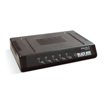
5.3 Description of LEDs The following LEDs are used to display normal operation condition and alarm condition. Status Alarm Normal operation Synch DSL line is not connected Link The Ethernet network is off – Power is off 1, 2, 3, 4 The hub port is not active –... -
Page 36: Mechanic Design
6 MECHANIC DESIGN The Black Box devices have three mechanic designs: 1. Sub-Rack is a unit to be mounted in 19’’ chassis (MDS920AE-RMDC); 2. Mini-Rack is a unit of 1U height (44.5 mm) to be mounted in 19’’ rack or a cabinet;... - Page 37 Fig. 16 MDS920C-10BT, NG, front panel Version: 1.0 Page. 37 of 95...
- Page 38 Mini-Rack From the constructive point of view, MDS922AE-10BT represents a case made of stainless steel and containing the basic elements of the device. Fig. 17 shows the front panel. The front panel has the following sockets and LEDs: Description Alarm Alarm LED Sync xDSL line status LED...
- Page 39 Fig. 17 MDS922AE-10BT, front panel Version: 1.0 Page. 39 of 95...
-
Page 40: Stand Alone
Stand Alone From the constructive point of view, MDS921AE-10BT represents a case made of shockproof polystyrene to withstand harsh environmental conditions and containing the basic elements of the device. The power supply unit represents an external power supply unit in the form of a plug. The panels have the following sockets and LEDs: Description Alarm... -
Page 41: Equipment Installation
7 EQUIPMENT INSTALLATION The installation and connection of the Black Box PAM devices is implemented in the following order: • before the installation, make sure that the set is complete; • mount the device in 19” shelf (for the devices of the Sub-Rack type), in 19” rack or cabinet (for the devices of the Mini-Rack type), or on horizontal surface (for the devices of the Stand Alone type);... - Page 42 • Switch the device on. The initialization takes of about 20 seconds. When the time lapses the device is ready for configuring from the control computer. Note! The device must be disconnected from power during the installation. DSL and computer connectors are described in Chapter 11. Version: 1.0 Page.
-
Page 43: Programming Guide
8 PROGRAMMING GUIDE 8.1 Introduction The equipment has built-in management and self-testing functions. The devices can be connected through the RS232 interface to the terminal or computer with a possibility of the terminal emulation for controlling and configuring. Note! The device, primarily configured through the RS232 interface, can be remotely controlled over the Telnet or HTTP protocols. - Page 44 ECHO↵ %01 %02 %08 %10 %11 %12 Management of devices of Mini-Rack and Stand Alone type The management terminal is connected to the MONITOR socket (DB9 type), which is on the front (for devices of the Mini-Rack type) or rear (for the devices of the Stand Alone type) panels. The requirements to the terminal configuration are similar to those of Sub-Rack devices.
- Page 45 Fig. 19 Command tree of bridge mode Version: 1.0 Page. 45 of 95...
- Page 46 Fig. 20 Command tree of router mode Version: 1.0 Page. 46 of 95...
-
Page 47: Main Menu Of The Bridge Mode
The factory setting assumes no password protection. If, nevertheless, after installation the modem asks for a password (it might happen for example if somebody used or tested the device before) please contact nearest Black Box service center or technical support team. 8.2.1 Help command The help command displays prompts with a list of available programs. -
Page 48: Default Command
Command format: home Parameter: no 8.2.3 Default command The default command sets the default settings. >> default The data set to default successfully. >> Command format: default Parameter: none 8.2.4 Lan command The Lan command puts the system in the Ethernet submenu. >>... -
Page 49: List Command
Command format: show Parameter: none Definitions: Ethernet ip: Subnet mask: 8.2.5 List command The list command displays the VC condition. >> list Port ethernet1 0: edd TxPkts: Port shdsl 0: oamloop TxPkts: xVPI/VCI: 1: oamloop TxPkts: xVPI/VCI: 2: oamloop TxPkts: xVPI/VCI: 3: oamloop TxPkts: xVPI/VCI:... -
Page 50: Manage Command
8.2.6 Manage command The manage command puts the system into the management submenu of the access to the device. >> manage > manage> Command format: manage [setpass] Parameter: Setpass: See 8.2.6.1 8.2.6.1 Setpass command The setpass command enables and disables the access password to the system. Password setting >... - Page 51 Password change > manage> setpass Old Password:**** New Password(press ENTER to disable):****** Confirm password again:****** Password has been changed Saving configuration... Configuration saved. > manage> Command format: setpass Parameter: none. Definitions: Old Password: New Password (press Enter to disable): Confirm password again: Password has been changed:...
-
Page 52: Mode Command
Are you sure to disable password (y/n): Password has been changed: Saving configuration…: Note! The maximal password length should be no more than 20 symbols. The password should be of Latin letters and figures. The symbol uppercase differs. 8.2.7 Mode command The mode command selects the device operation mode: bridge or router. -
Page 53: Quick Command
Definitions: Please select bridge or router: Current mode is router: Note! The mode command changes the list of available commands in the main menu. 8.2.8 Ping command The ping command enables testing and allows checking the network efficiency. >> ping 10.0.1.55 >>... -
Page 54: R1483 Command
0 PVC existed, 8 PVCs available. VPI(0-4095): 8 VCI(1-65535): 35 Packet Filter ( Any/Ip/Pppoe ): a Add another PVC ? (y/n): n Enable Spanning tree? (y/n) : n Configuration MODE: Bridge FUNCTION: R1483 Spanning Tree: Disable 1: 8 Preserve the configuration (y/n) : y Configuration will have no effect until after save and restart. - Page 55 Parameter: Delpvc: See 8.2.10.1 Pfilter: See 8.2.10.2 Setpvc: See 8.2.10.3 Setqos: See 8.2.10.4 Setspan: See 8.2.10.5 Show: See 8.2.10.6 8.2.10.1 Delpvc command The delpvc allows to delete one or all PVCs. > r1483> delpvc all > r1483> Command format: delpvc <all>|[<vpi>/]<vci> Parameter: All: VPI/VCI:...
- Page 56 > r1483> setpvc 8/35 llc > r1483> Command format: setpvc [<vpi>/]<vci> [llc/vcmux] parameter: VPI/VCI: Sets PVC with the VPI/VCI number. LLC/VCMUX: Shows the encapsulation type according to RFC1483. 8.2.10.4 Setqos command The setqos command sets the priority for the active PVC. >...
-
Page 57: Restart Command
Pkt Filter: 8.2.11 Restart command The restart command reboots the system. >> restart NBfs2 Helium Family PP flash boot 6.1.0.25 (22 October 1999) (c) Copyright BLACK BOX 1999 SDRAM size = 0x800000, type = 0x2 NPnNo Booting... System start... >>... -
Page 58: Shdsl Command
Helium Family PP flash boot 6.1.0.25 (22 October 1999) (c) Copyright BLACK BOX 1999 SDRAM size = 0x800000, type = 0x2 NPnNo Booting... System start... >> Command format: save Parameter: none. Note! The save command restarts the system. 8.2.13 Shdsl command The shdsl command puts the system into the submenu of the shdsl line. - Page 59 8.2.13.2 Enable command The enable command activates the last settings of shdsl without them being saved and restarted. > shdsl> enable > shdsl> Command format: enable Parameter: none. 8.2.13.3 Terminal command The terminal command sets the device as the master or slave. >...
- Page 60 8.2.13.5 Fix command The fix command sets the manual mode of line rate adjustment. > shdsl> fix 768 > shdsl> Command format: fix <rate> Parameter: rate: Displays the rate at which the connection will according n*64+i*8+8, where n is efficient capacity (1≤ n <36), and i is a header (i=0 | 1).
- Page 61 Note! The adaptive mode must be configured on the slave device. If the manual mode is configured on the master device, the line rate will be set according to the fix parameter of the master device. If the automatic mode is configured on the master device, the line rate will depend on the DSL line quality.
-
Page 62: Main Menu Of The Router Mode
8.2.14 Show command The show command displays the modem IP address and active PVC settings. >> show Ethernet ip: 192.168.1.1 Subnet mask: 255.255.255.0 FUNCTION VPI/VCI Rfc1483 8/35 >> Command format: show Definitions: Ethernet ip: Subnet mask: Function: VPI/VCI: CLASS: LLC/VCMUX: Spanning: Pkt Filter: 8.2.15 Ver command... - Page 63 Command formate: dnsrelay [setdnsip <dnsip> [<retry times>] | show] Parameter: Setdnsip: See 8.3.2.1 Show: See 8.3.2.2 8.3.2.1 Setdnsip command The setdnsip command sets the DNS-server address. > dnsrelay> setdnsip 10.0.0.50 3 Command format: dnsrelay [setdnsip <dnsip> [<retry times>] Parameter: Dnsip: IP address of the DNS server Retry times:...
-
Page 64: Ipoa Command
8.3.3 Ipoa command The ipoa command puts the system into the menu of connection settings of IP over ATM. >> ipoa > ipoa> Command format: ipoa [delwanip | setqos | setrip | show] Parameter: Delwanip: See 8.3.3.1 Setqos: See 8.3.3.2 Setrip: See 8.3.3.3 Show:... - Page 65 Note! The setqos command changes the PVC parameters, first configured by the quick command (see 8.2.9) or the setwanip command (see 8.3.3.4). If the mentioned PVC is not found, the system displays an error message. 8.3.3.3 Setrip command The setrip command sets the RIP type for the used PVC. >...
-
Page 66: Lan Command
8.3.3.5 Show command The show command displays the IP configuration over ATM. > ipoa> show IPoA setting: FUNCTION VPI/VCI CLASS IPoA 8/35 Command format: show Definitions: VPI/VCI: Wanip/MaskNum: GatewayIP: RIP: 8.3.4 Lan command The lan command puts the system into the menu of local Ethernet interface parameter settings. >>... - Page 67 > lan> Command format: dhcpserver <range1 startIP> <range1 endIP> [<range2 startIP> <range2 endIP>] [<max-lease-time>] dhcpserver dns <dns ip1> [<dns ip2>] Parameter: Range1 startIP: The starting IP address of the first range. Range1 endIP: The end IP address of the first range. Range2 startIP: The starting IP address of the second range.
-
Page 68: Manage Command
> lan> Command format: setdhcp [server|disable] Parameter: Ethernet ip: Subnet mask: DHCP current setting : DHCP ineffective setting : 8.3.5 List command See 8.2.5 8.3.6 Manage command See 8.2.6 8.3.7 Mode command See 8.2.7 8.3.8 Pat command The pat command puts the system into the menu of NAT address translations settings. >>... - Page 69 Command format: addpatin <pppoa|pppoe|wanip> <port>/<udp|tcp> <serverip> Parameter: Wanip: Port Udp|tcp Serverip 8.3.8.2 Delpatin command The delpatin command deletes the addpatin command. > pat> delpatin all > pat> Command format: delpatin <all>|<number> Parameter: all: Deletes all the connections. Number: The virtual connection number, displayed by the show command.
-
Page 70: Pppoa Command
i/f name|WanIP pppoa 434/udp 210.62.2.195 232/tcp > pat> Command format: show Definitions: Interface: IP address: i/f name|WanIP Port/Protocol: Server IP 8.3.9 Ping command See 8.2.8 8.3.10 Pppoa command The pppoa command puts the system into the menu of PPP over ATM settings. >>... - Page 71 8.3.10.1 Adduser command The adduser command activates VC, assigning the VPI/VCI addresses and sets the user’s name and the password for PPP over ATM connections. > pppoa> adduser 8/35 Access chap New Password:******* Confirm password again:******* User account added successfully. >...
- Page 72 8.3.10.4 Echo command The echo command enables and disables the LCP response (the process of the control connection). LCP is used to confirm the established PPP connection, the interval time between the LCP responses can be changed. > pppoa> echo 120 >...
-
Page 73: Pppoe Command
8.3.10.7 Setrip command The setrip command sets the RIP type for the active connection of PPP over ATM. > pppoa> setrip 1 > pppoa> Command format: setrip <1|2|1&2|0> Parameter: 1&2: 8.3.10.8 Show command The show command displays the configuration of the current PPP over ATM connection. >... -
Page 74: R1483 Command
8.3.12 R1483 command The r1484 command puts the system into the menu of RFC1483 encapsulation settings. >> r1483 > r1483> Command format: r1483 [delwanip <all>|[<vpi>/]<vci> | setqos [<vpi>/]<vci> <ubr|cbr|vbr(nrt)> | setrip [<vpi>/]<vci> <1|2|1&2|0> | setwanip setwanip [<vpi>/]<vci> <wanip[/<masknum>]> [llc/vcmux] | show] Parameter: Delwanip: Setqos:... - Page 75 Parameter: VPI/VCI: UBR: CBR: VBR: VBRNRT: 8.3.12.3 Setrip command The setrip command sets the RIP type for the used PVC. > pppoa> setrip 1 > pppoa> Command format: setrip <1|2|1&2|0> Parameter: VPI/VCI 1&2: 8.3.12.4 8.3.12.4 Setwanip command The setwanip command sets the IP address of the SHDSL (WAN) interface for the selected PVC. >...
-
Page 76: Quick Command
8.3.12.5 Show command The show command displays the r1483 configuration. > r1483> show RFC1483 setting: FUNCTION VPI/VCI Rfc1483 8/35 > r1483> Command format: show Definitions: VPI/VCI: Wanip/MaskNum: Class: RIP: 8.3.13 Quick command The quick command allows to set quickly the connection with the help of prompts. >>... -
Page 77: Restart Command
8.3.14 Restart command See 8.2.11 8.3.15 Rtable command The rtable puts the system into the menu of routing table settings. >> rtable > rtable> Command format: rtable [addiproute | deliproute | show] Parameter: Addiproute: Deliproute: Show 8.3.15.1 Addiproute The addiproute command adds a new route in the routing table. >... -
Page 78: Shdsl Command
Parameter: all: number: 8.3.15.3 Show command The show command displays the routing table. > rtable> show Routing Table: No. Destination IP 0.0.0.0 198.24.67.0 effective routing table: Routing table is empty > rtable> Command format: show Parameter: Destination IP: SubMask Gateway IP 8.3.16 Save command See 8.2.12 8.3.17 Shdsl command... -
Page 79: Firmware Loading Guide
9 FIRMWARE LOADING The device hardware allows to implement new possibilities and functions by updating its firmware. To facilitate the firmware update, there exists a command file. The upgrade is implemented over TFTP. It is recommended to update the firmware in the manufacturer or provider’s (supplier) service center. -
Page 80: Network Management Interface
10 TECHNICAL SPECIFICATIONS 10.1 Interfaces 10.1.1 Monitor interface Parameter Interface Transmission mode Interface type Terminal emulation mode Transmission format Flow management Transmission rate 10.1.2 Network management interface Parameter Interface Supported protocols 10.1.3 SHDSL interface Parameter Transmission standard Cable Number of pairs Transmission rate Line code Version: 1.0... -
Page 81: Network Interface
For transmission rate, Kbit/s: 1032 1544 2056 10.1.4 Network interface Parameter Transmission rate Transmission medium Standard Bridge Encapsulation Routing Protocols 10.2 Power supply Parameter Input direct current voltage range Input alternating current voltage range Power consumption Version: 1.0 Frequency transmission range, kHz 0…67 0…88 0…131... -
Page 82: Protection Against Dangerous Affects
10.2.1 Protection against dangerous affects The protection of the equipment against dangerous interfering affects meets the requirements of ITU-U K20/K.21 10.2.2 Surge safety Parameter The resistance between the ground terminal and isolated parts of the device Insulation resistance of the device electrical circuit Test voltage for ungrounded electrical circuit relative to the... -
Page 83: Guarantee
10.4 10.4 Guarantee The Mean Time Between Failure is not less than 3x10 The operating lifetime is no less than 20 years. 10.5 10.5 Physical dimensions Stand Alone (dimensions, weight) Mini-Rack (dimensions, weight) Sub-Rack (dimensions, weight) Version: 1.0 hours. 220 mm х 170 mm х 40 mm, 0.5 kg 483 mm х... -
Page 84: Connectors' Description
11 CONNECTORS’ DESCRIPTION 11.1 SHDSL connector Type: RJ-11, 4 pin Pin Signal Description – LA,a SHDSL pair, tip LA,b SHDSL pair, ring – 11.2 Monitor connector Type: Sub-D9, female female Pin Signal Description – Transmit data Receive data ALACOM Common contact of Alarm Relay SGND Signal ground DA_NC... -
Page 85: Ethernet (10Baset) Connector
ND_NO Non Urgent-Alarm contact, normally open 11.3 Ethernet (10BaseT) connector Type: RJ-45 11.4 Power connector (For MDS922AE-10BT) Type: Molex, 4 pin Pin Signal Version: 1.0 RJ45 Description -PWR negative power supply terminal PROT Grounding – +PWR positive power supply terminal For Mini-Rack units Description Page. -
Page 86: Description Of Interface Cables
12 DESCRIPTION OF INTERFACE CABLES 12.1 «Direct» Ethernet cable The cable contains two pairs: Side А Color white/orange orange/white white/blue blue/white The cable contains four pairs: Side А Color white/green green/white white/orange blue/white white/blue orange/white white/brown. brown/white Version: 1.0 Side B Side B Page. -
Page 87: Cross-Over Ethernet Cable
12.2 Cross-over Ethernet cable The cable contains only two pairs: Side А Color white/orange orange white/blue blue The cable contains four pairs: Side А Color white/green green white/orange blue white/blue orange white/brown brown 12.3 Monitor connector Device Computer DB9M DB9F Version: 1.0 Side B Side B... -
Page 88: Delivery Set
13 DELIVERY SET (see the technical passport) Typically the delivery set includes: • SHDSL modem • AC power adapter (for Stand Alone versions only) • AC power cable (for MiniRack versions only) • Ethernet cable • User Manual (in some cases can be made available on a disk or web site) Version: 1.0 Page. -
Page 89: Glossary
14 GLOSSARY DSL (digital subscriber line) Digital technology that provides high-speed data transmission over physical wiring (twisted pair), used to connect telephones. Digital data rate of 2048 Kbit/s structured according to ITU-T G.704. G.703 ITU-T standard regulating electrical and mechanical specifications for connections. G.704 ITU-T standard regulating synchronous structures for the first and second hierarchical layers. - Page 90 International body that develops worldwide standards for telecommunications technologies. LAN (local-area network) LANs connect workstations, servers, terminals, printers and other devices in a single building or other geographically limited area. LANs use special operating systems to transmit data at high speeds.
- Page 91 Time Division Multiplexing Synchronous Digital Hierarchy Virtual Path Identificator VСI Virtual Channel Identificator Version: 1.0 Page. 91 of 95...
-
Page 92: Example Of Network Configuration
15 EXAMPLE OF NETWORK CONFIGURATION Consider the following example of router configuration in MDS92xxx-10BT modems. Fig. 13 shows the network structure. Network 198.24.67.0/24 Network 194.27.54.0/24 Workstation IBM Compatible Workstation Workstation 216.71.89.12 216.71.89.3 Router1 Router2 198.24.67.20/24 194.27.54.10/24 Fig.13 network With the help of the mode command select the routing mode for the modem. The following message notifies you that the current mode now is router. - Page 93 When the following message “R1483(r)/IpoA/PPPoA(p)” appear, type “IpoA” and press “enter”. Enter the IP address, which will belong to the router. In our case, it is 198.24.67.20 with mask 255.255.255.0. The system requires to enter VPI and VCI. Type 8 and then press “enter” after it, type 35, and press “enter”.
-
Page 94: Router 2
Enter 216.71.89.3. Note! IP addresses of WAN interfaces must be in the address field of one network. In our case this is network 216.71.89.0 with mask 255.255.255.0. After it, on request to add next PVC, type “n” and press “enter”. Then save the configuration, and restart the modem. - Page 95 WAN IP: 216.71.89.3 Gateway: 216.71.89.12 Now it is necessary to reinitialize router 2. After restart of the system, let us check operability of the created network. Enter the command “ping 198.24.67.20 on router 2. The configuration is completed successfully. Version: 1.0 Page.
Need help?
Do you have a question about the Version 1.0 and is the answer not in the manual?
Questions and answers