
Related Manuals for Newport ORIEL INSTRUMENTS OPS-A150


Summary of Contents for Newport ORIEL INSTRUMENTS OPS-A150
- Page 1 OPS-A150, OPS-A500, OPS-A1000 ® Oriel Arc Lamp Power Supplies User's Manual Family of Brands – ILX Lightwave • New Focus™ • Ophir • Corion • Richardson Gratings™ • Spectra-Physics ® ® ® 90074224 MOPS-A, Rev C 7/25/19...
-
Page 2: Table Of Contents
OPS-A Arc Lamp Power Supplies Page 2 1 GENERAL INFORMATION ..................5 1.2 GENERAL WARNINGS ......................6 1.3 ELECTRICAL HAZARDS ......................7 1.4 FIRE HAZARDS ......................... 7 1.5 LAMP HANDLING ........................7 1.6 LIGHT HAZARDS ........................7 2 INTRODUCTION ......................8 2.1 DESCRIPTION/FEATURES ...................... - Page 3 OPS-A Arc Lamp Power Supplies Page 3 11.4 TTL SIGNAL POLARITY ......................50 11.5 TIMED SHUTTER MODE ...................... 50 11.6 DOSED SHUTTER MODE ....................52 11.7 EXTERNAL SHUTTER CONTROL METHODS ..............54 12 AUDIO WARNING ....................55 12.1 AUDIO WARNING SETUP ....................56 13 MEMORY .........................
- Page 4 OPS-A Arc Lamp Power Supplies Page 4 Figure 11 The label directing which electrical connector to use for each lamp housing interconnection cable on a 450-1000 W Research Lamp Housing..................36 Figure 12 The Interlock Open and warning symbol indicator of the power supply indicates a cable is disconnected and/or the lamp housing is open.
-
Page 5: General Information
The safety of any system incorporating the OPS power supply is the sole responsibility of the assembler of the systems. If the equipment is used in a manner not specified by Newport Corporation, the protection provided by the equipment may be impaired. -
Page 6: General Warnings
OPS-A Arc Lamp Power Supplies Page 6 1.2 GENERAL WARNINGS • Read all warnings and operating instructions for this system prior to setup and use. • Do not use this equipment in or near water. • To prevent damage to the equipment, read the instructions in the equipment manual for proper input voltage. -
Page 7: Electrical Hazards
Each compatible Newport brand lamp housing is equipped with a condenser lens. The re-focused output of this lens can cause ignition of flammable targets including but not limited to walls, certain chemicals. -
Page 8: Introduction
Icons on the LCD display show the ignition and open/close statuses of the lamp during operation at all times. • Safety interlock connector for safeguarding against accidental exposure to UV light when used with a Newport lamp housing. • USB interface located on front panel for firmware updates. •... -
Page 9: Dimensions
OPS-A Arc Lamp Power Supplies Page 9 2.2 DIMENSIONS Figure 1 Dimensional drawing of the OPS Series Power Supplies. -
Page 10: Arc Lamp Compatibility
Page 10 2.3 ARC LAMP COMPATIBILITY Newport Corporation offers all the components required to assemble a complete illumination system. The minimum components include a lamp, lamp housing, power supply, and possibly a socket adapter. The table below explains which components are compatible with each other to create an illumination system. - Page 11 OPS-A Arc Lamp Power Supplies Page 11 OPS-A500 Lamp Compatibility Table Compatible Oriel Lamp Housings Q Housing Research Lamp Housings Power Lamp Lamp Rating, [Socket Supply Description Adapter] [Socket Adapter] 66901, 66902, 66905, 67001, 67005 6283NS Hg 200W [66144] 66901, 66902, 66905, HgXe 200W 67001, 67005 6290...
-
Page 12: System Setup
OPS-A Arc Lamp Power Supplies Page 12 OPS-A1000 Lamp Compatibility Table Compatible Oriel Lamp Housings Q Housing Research Lamp Housings Power Lamp Lamp Rating, [Socket Supply Description Adapter] [Socket Adapter] 66921, 66923 Xe 450W 6278 (UV ENHANCED) [6163] 66921, 66923 Xe 450W 6280NS (OZONE FREE) -
Page 13: Choosing A Location
Arc Lamp Power Supplies Page 13 If any item is missing or damaged, immediately contact Oriel Instruments or the Newport representative from whom the system was purchased. It is suggested to save the packaging material and shipping container, in case the equipment needs to be relocated at a future date. -
Page 14: Power Supply Connections
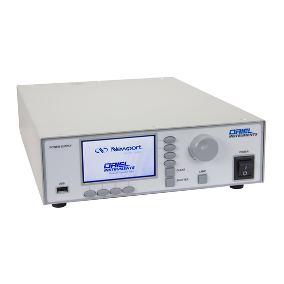
OPS-A Arc Lamp Power Supplies Page 14 3.4 POWER SUPPLY CONNECTIONS 3.4.1. Front Panel Controls/Connections Figure 2 OPS-A Power Supply Front Panel Connections. A. USB. The USB connector on the front panel is used to install firmware and LCD GUI updates to the power supply. -
Page 15: Rear Panel Controls/Connections (Ops-A150, Ops-A500 Models Only)
OPS-A Arc Lamp Power Supplies Page 15 F. LAMP. The LAMP button is for manual control of the lamp. When pressed, the lamp will ignite/power down. G. Control knob. The control knob is for setting the parameters specific to each power supply feature. H. - Page 16 OPS-A Arc Lamp Power Supplies Page 16 A dedicated power line or line isolation may be required in certain locations, as the electronics contained in the instrument are sensitive to static electricity and radiated electromagnetic fields. Operation of the system near intense pulsed sources (lasers, Xenon flash lamps, etc.) may compromise performance. Before making any electrical connections, verify the power switch is in the OFF position for the OPS.
- Page 17 INTERLOCK (+) Connected to +12V to satisfy interlock +12 VDC DC voltage for interlock (fan/elapsed time indicator if in housing) IGNITOR DRIVE Momentary ground connection to fire Newport ignitor INTERLOCK (-) Connected to GND to satisfy interlock MATING CONNECTOR: Body:...
- Page 18 If there are any questions or concerns, contact Oriel Instruments or the regional sales representative for Newport. F. TRIGGER INPUT. The BNC connector labeled TRIGGER INPUT is to remotely control the operation of a shutter that is connected to the power supply.
-
Page 19: Rear Panel Controls/Connections (Ops-1000 Model Only)
OPS-A Arc Lamp Power Supplies Page 19 3.4.3 Rear Panel Controls/Connections (OPS-1000 model only) A. AC IN. Before powering up the system for the first time, it is suggested to have a qualified electrician verify the wall socket to be used with the power supply meets the requirements for operation as noted. The line voltage requirement for the OPS-A1000 is 95-264 VAC, 47 to 63 Hz. - Page 20 OPS-A Arc Lamp Power Supplies Page 20 ELECTRICAL SHOCK HAZARD To avoid electric shock, connect the instrument to a properly earth- grounded, 3-prong receptacle only. Failure to observe this precaution can result in severe injury or death. Never attempt to open the power supply. These models do not contain any user serviceable parts.
- Page 21 INTERLOCK (+) Connected to +12V to satisfy interlock +12 VDC DC voltage for interlock (fan/elapsed time indicator if in housing) IGNITOR DRIVE Momentary ground connection to fire Newport ignitor INTERLOCK (-) Connected to GND to satisfy interlock MATING CONNECTOR: Body:...
- Page 22 INTERLOCK (+) Connected to +12V to satisfy interlock +12 VDC DC voltage for interlock (fan/elapsed time indicator if in housing) IGNITOR DRIVE Momentary ground connection to fire Newport ignitor INTERLOCK (-) Connected to GND to satisfy interlock MATING CONNECTOR: Body:...
- Page 23 OPS-A Arc Lamp Power Supplies Page 23 CAUTION Do not turn on the power supply until the lamp has been installed and all connections have been made to the power supply and lamp housing. WARNING When the Lamp On button is depressed, the lamp will begin emitting light. Do not press the Lamp On button until the output flange is directed in such a way that people, animals and equipment will not be harmed by the light.
-
Page 24: Initial Start-Up Screen
OPS-A Arc Lamp Power Supplies Page 24 3.5 INITIAL START-UP SCREEN Upon powering up the OPS-A Model Power Supply. The following screen will appear on the power supply’s LCD: Figure 4 The LCD display of the OPS-A Model Power Supply. A. -
Page 25: Quick Start Guide
OPS-A Arc Lamp Power Supplies Page 25 E. Display. Pressing the horizontal menu button under this icon will reveal the vertical menu listing the display options available by the OPS-A Model Power Supply. F. Setup. Pressing the horizontal menu button under this icon will allow the user to Save and Load preferred settings, reset the amount of hours the OPS-A has been recording for the current lamp in use, and access other functions of the power supply. -
Page 26: Light Intensity Control
OPS-A Arc Lamp Power Supplies Page 26 4.3 LIGHT INTENSITY CONTROL The flux set point must be set first. There are two ways to set the flux set point: A. AutoSet method: i. Use “Current” or “Power” mode to turn ignite the lamp first ii. -
Page 27: Operating Modes
OPS-A Arc Lamp Power Supplies Page 27 When in “Intensity” mode, if the signal output and/or TE cooler cables connecting the power supply to the 71582 light intensity control kit detector are not connected properly, “Cooler Not Ready” may appear on the message bar of the LCD screen. If this appears, inspect the cables to confirm secure connections. -
Page 28: Power And Current Operation Modes
Be aware that Pmax cannot be changed when the lamp is ignited. Note. If using a lamp purchased from Newport Corporation, set Pset to the desired operating power. Pmax is typically set at 10% higher than the lamp rating. If not using a lamp purchased from Newport Corporation, it is best to follow operation power and maximum power supply guidelines determined by the lamp manufacturer. - Page 29 OPS-A Arc Lamp Power Supplies Page 29 3. Press CLEAR to clear the vertical menu from the screen and observe the desired operating parameter in real time while the lamp is being operated. The lamp is now ready for ignition. If the “Warning Imax Setting”...
-
Page 30: Current Operation Mode
Note. If a lamp that was not purchased from Newport Corporation is being used, use the manufacturer’s current specifications for operation. If the lamp operating power and voltage are known but the operating current is not, determine the current setting by using Ohm’s Law:... -
Page 31: Firmware And Model Information
OPS-A Arc Lamp Power Supplies Page 31 4. Press CLEAR to clear the vertical menu from the screen and observe the desired operating parameter in real time while the lamp is being operated. The lamp is now ready for ignition. Please note that the lamp operation mode cannot be changed while the lamp is being operated. -
Page 32: Updating The Firmware
If firmware updates crucial to the operation of the power supply or LCD screen graphic updates (LCD GUI) are made in the future, these updates will be available on the Newport website (http://www.newport.com/). Updates can be done as firmware only, image only, or both firmware and image by simply copying the desired files into the root directory of a USB flash drive. -
Page 33: Figure 6 The Lcd Screen Image Displayed During Firmware And Lcd Gui Interface Updates
OPS-A Arc Lamp Power Supplies Page 33 Figure 6 The LCD screen image displayed during firmware and LCD GUI interface updates. 5. When the update has been completed, the LCD will display the regular LCD GUI interface. 6. If the update involved a firmware update, confirm the firmware update was successful by confirming the firmware version as shown by the procedure explained previously in this section of the manual. -
Page 34: Interlock Cables/Connections To Lamp Housings
A lamp interconnection cable must be purchased for use with an arc lamp housing, based on the type of lamp being utilized. Replacement cables may also be purchased if needed. Interconnection cables are available on Newport.com. Lamp Housing Interconnection Cables (6 foot,... -
Page 35: Connection To A Q Series Type Housing
OPS-A Arc Lamp Power Supplies Page 35 Figure 8 Labels on the OPS-A1000 Power Supply and Research Lamp Housing indicating the proper connector for each type lamp housing interconnection cable. If a replacement cable is needed, please contact Oriel Instruments. Oriel Instruments can only guarantee that the OPS Power Supply will meet performance specifications and be operated safely if lamp housing interconnection cables provided by Oriel Instruments as listed in the table on the previous page are used. -
Page 36: Connection To A Research Lamp Housing
OPS-A Arc Lamp Power Supplies Page 36 8.2 CONNECTION TO A RESEARCH LAMP HOUSING 8.2.2 Connecting the OPS-A250/OPS-A500 to a Research Lamp Housing For connecting the OPS-A250 or OPS-A500 to a Research Lamp Housing, use the proper cable to suit the type of DC arc lamp used as designated in the table early in this section and the label fixed to the Research Lamp Housing. -
Page 37: Safety Interlock
Page 37 8.3 SAFETY INTERLOCK Newport’s Oriel Power Supplies have a safety interlock feature which must be satisfied before the power supply will power the lamp and which, if broken during operation, will disable the power supply. Overheating of the housing or accidental opening of the door will automatically shut down the power supply. -
Page 38: Detector Thermoelectric Cooling (Applicable For Lik-Lmp)
OPS-A Arc Lamp Power Supplies Page 38 9 DETECTOR THERMOELECTRIC COOLING (APPLICABLE FOR LIK-LMP) Although the OPS-A Series Power Supply outputs a highly stable voltage and power output with minimum ripple, users may notice instable output of the lamp. This is due to factors beyond the control of the power supply such as lamp aging, ambient temperature fluctuations, and electrode erosion. -
Page 39: Figure 14 Setting The Te Cooler Temperature
OPS-A Arc Lamp Power Supplies Page 39 reading. A more accurate light intensity reading allows the OPS-A Model Power Supply to more accurately determine the proper current/power to supply to the lamp to keep output power constant. To change the temperature of the 75182, press the horizontal menu button under the Setup icon on the LCD interface until the vertical menu showing CoolTemp, Idle, and Autoset appear on the right as shown on the next page. -
Page 40: Intensity Operation Mode (Lik-Lmp Required)
OPS-A Arc Lamp Power Supplies Page 40 10 INTENSITY OPERATION MODE (LIK-LMP REQUIRED) Intensity Operation Mode of the OPS-A Model Power Supply requires the use of the LIK-LMP Light Intensity Controller kit (sold separately), also from Oriel Instruments. With the help of the 71582 TE Cooled Detector head used to monitor and relay constant feedback of the lamp output to the OPS Power Supply described... - Page 41 OPS-A Arc Lamp Power Supplies Page 41 COOLING 9 DETECTOR THERMOELECTRIC , a specific output intensity can be established by the user, monitored, and maintained over long periods of operation. For applications in which a precise monochromatic or luminous light power is required, a user may first need to adjust current/power supplied to the lamp while using a photosensor calibrated to NIST or other strict standards.
-
Page 42: Mounting The Lik-Lmp To A Q Series Or Research Lamp Housing
OPS-A Arc Lamp Power Supplies Page 42 10.1 Mounting the LIK-LMP to a Q Series or Research Lamp Housing 1. If an Oriel Products Series Q Housing is being used, use the 68954 Adapter Kit to couple the 71582 detector head to the Series Q Housing. If an Oriel Products Research Lamp Housing is being used, use the 68952 Adapter Kit to couple the 71582 detector head to the Research Lamp Housing. -
Page 43: Figure 16 Exploded View Of 71582 Mounting To A Research Lamp Housing Using The 68952 Adapter Kit
OPS-A Arc Lamp Power Supplies Page 43 Figure 16 Exploded view of 71582 mounting to a Research Lamp Housing using the 68952 Adapter Kit. 2. Connect the 4 pin connector end of the 70062 cable to the 4 pin output connector on the rear of the 71582 Detector Head. -
Page 44: Figure 17 The Detector Input And Te Cooler Output Ports Are For Direct Use Of The Lik-Lmp With The Ops-A Power Supply
OPS-A Arc Lamp Power Supplies Page 44 Figure 17 The DETECTOR INPUT and TE COOLER output ports are for direct use of the LIK-LMP with the OPS-A Power Supply. Figure 18 The 70062 (left) and 70018 (right) required for interfacing the 71582 Detector Head with OPS-A Arc Lamp Power Supply. - Page 45 OPS-A Arc Lamp Power Supplies Page 45 4. Press the horizontal menu button under the Display indicator on the LCD screen and observe the vertical Display menu appear on the right of the screen. Use the knob to the right of the LCD screen to toggle the display to Lamp Intensity as indicated by the red dot to the left of each option.
-
Page 46: Idle Function
OPS-A Arc Lamp Power Supplies Page 46 Figure 19 Selecting Intensity Mode as the Operating Mode of the OPS-A Power Supply. Each changeable parameter on the vertical menu that appears when selecting Intensity mode is defined below: Flux Set- Flux Set is the output current of the 71582 detector head of the LIK-LMP. If the Autoset process in Step 4 was used prior to changing the lamp operating mode to Intensity Mode, the Flux Set value will display the Autoset value. - Page 47 OPS-A Arc Lamp Power Supplies Page 47 To change the Iidle, press the vertical soft key menu button near the Iidle interface icon and observe a red bullet appear on the left of the current Iidle value. Then, use the knob to increase or the Iidle value as desired.
-
Page 48: Shutter Controller
OPS-A Arc Lamp Power Supplies Page 48 Figure 20 Idle Function Setup. 11 SHUTTER CONTROLLER The OPS power supplies enable users to control a shutter that responds to a TTL signal. Users may control the shutter using a variety of methods. Manual mode A front panel button toggles the shutter open or closed. -
Page 49: Shutter Status
OPS-A Arc Lamp Power Supplies Page 49 11.1 SHUTTER STATUS The shutter status is indicated on the power supply display at all times. If a shutter is not being used in the system, by default it will appear as closed on the display. Note: the power supply does not receive feedback from the shutter as to whether it is functioning correctly. -
Page 50: Figure 23 Manual Shutter Mode (Shutter Closed)
OPS-A Arc Lamp Power Supplies Page 50 Figure 23 Manual Shutter Mode (Shutter Closed). To toggle the shutter open or closed, press the button labeled SHUTTER on the front face of the power supply. Figure 24 Manual Shutter Button. 11.3 TTL SHUTTER CONNECTION Any shutter that can be driven by a TTL signal may be controlled by the OPS power supply. -
Page 51: Ttl Signal Polarity
OPS-A Arc Lamp Power Supplies Page 51 Figure 25 Shutter Output Connector. 11.4 TTL SIGNAL POLARITY The settings of the OPS-A Model Power Supply can be adjusted to output both positively and negatively biased TTL pulses depending on the requirements of the external shutter being used. To adjust this TTL signal output polarity, access the System 1 setup menu as shown below: Press the vertical menu button next to the Shutter indicator. - Page 52 OPS-A Arc Lamp Power Supplies Page 52 1. To operate the shutter in Timed Shutter Mode, press the horizontal menu key under the Shutter indicator until Timed appears under the Shutter indicator and the corresponding vertical menu as shown below appears: 2.
-
Page 53: Dosed Shutter Mode
OPS-A Arc Lamp Power Supplies Page 53 may be set from 10 ms to 99.99 hours. To adjust the Close Time, when press the vertical menu key next to this indicator until the increment of time to be adjusted flashes. Then use the external knob to increase or decrease the timing value as required. - Page 54 OPS-A Arc Lamp Power Supplies Page 54 1. To use Dosed Shutter Mode, begin operating the lamp in Intensity Control Mode. Set the Flux Set, Flux Multiplier, Iidle, and Imax parameters as necessary/required. 2. Press the horizontal menu key under the Shutter indicator until Dosed appears in the indicator with the corresponding vertical menu as shown below: 3.
-
Page 55: External Shutter Control Methods
OPS-A Arc Lamp Power Supplies Page 55 key next to this indicator until the increment of time to be adjusted flashes. Then use the external knob to increase or decrease the timing value as required. Repeat # This button allows users to set the number of times an exposure repeats. The default is 1 cycle. When a red bullet appears next to the current Repeat# setting, use the external knob to increase or decrease this value as required. -
Page 56: Audio Warning
OPS-A Arc Lamp Power Supplies Page 56 If the shutter is set to manual mode and a TTL signal is sent to the Trigger Input connector, the shutter remains open for the duration of the Low signal. Figure 26 Trigger Example. By default, the shutter opens when a TTL Low signal is sent through the Trigger Input connector. -
Page 57: Figure 27 Warning Icon
OPS-A Arc Lamp Power Supplies Page 57 Error Message Condition Lamp housing connection cable became loose or Interlock Open lamp housing door were opened when the lamp was ignited Ignition failure during operation of the lamp. A very Ignition Failed low current draw from the lamp was detected The internal temperature of the power supply’s heat Heatsink Over Temp... -
Page 58: Saving Settings
OPS-A Arc Lamp Power Supplies Page 58 3. When done, press the CLEAR button to clear the menu from the screen. 13 MEMORY The OPS power supply automatically retains the last settings that were in effect prior to powering down the unit. -
Page 59: Loading Settings
OPS-A Arc Lamp Power Supplies Page 59 To save settings press the horizontal menu button under the Setup indicator on the LCD screen until Save appears under the Setup icon as shown above. Select one of the four available Setup spaces to store the current operating and press the vertical menu button next to that Setup space. -
Page 60: Power Supply Cleaning
OPS-A Arc Lamp Power Supplies Page 60 Figure 30 Loading Saved Settings From Memory. Loading a previously saved Setup is very similar to the method used to save that Setup. Press the horizontal menu button under the Setup indicator until Load appears under Setup as shown above. Press the vertical menu button next to the Setup space the desired settings were saved under. -
Page 61: Lamp Lifetime And Replacement
OPS-A Arc Lamp Power Supplies Page 61 16 LAMP LIFETIME AND REPLACEMENT The anode and cathode of an arc lamp are made of tungsten. The cathode is small and pointed to ensure that the tip reaches a high temperature for efficient electronic emission. The anode is more massive to withstand the electron bombardment and efficiently dissipate the heat produced. -
Page 62: Displaying Total Lamp Hours
OPS-A Arc Lamp Power Supplies Page 62 17 DISPLAYING TOTAL LAMP HOURS Press the button underneath “Display” on the front panel. Use the scroll wheel on the power supply until Lamp Hours is selected. Press the Display or CLEAR button in order to view the number of hours the lamp has been turned on. - Page 63 OPS-A Arc Lamp Power Supplies Page 63 If necessary, the monitoring of any time interval while the lamp is ignited can be done with the use of an external shutter and the Display settings.
-
Page 64: Ops-A Series Overview
OPS-A Arc Lamp Power Supplies Page 64 18 OPS-A SERIES OVERVIEW OPS-A150 OPS-A500 OPS-A1000 Approved Lamp 50 – 150 W 200 – 500 W 450 – 1000 W Wattage Power Factor >0.99 95 – 264 VAC Input Voltage Input Current Max 13 A 47 –... -
Page 65: Troubleshooting
CE and RoHS 19 TROUBLESHOOTING This chart provides the basic troubleshooting information for the Newport Model OPS power supplies when used with Newport lamp housing. Contact a Newport sales engineer or your local representative if more information is required. Symptom Action Power supply does not turn on, e.g. - Page 66 • Attempt ignition with a new lamp. • If fault repeats contact Newport for RMA information. Shutter icon indicates the opposite of In the System1 setup menu, change the Shutter setting to reflect its actual status with external shutter the required TTL signal polarity.
- Page 67 OPS-A Arc Lamp Power Supplies Page 67 Fault light This message will flash for 2 seconds if the user tries to change Display shows “Change Shutter the Lamp Mode from Intensity Mode to another mode while the Mode 1st” Shutter Mode is in Dosed Mode. •...
- Page 68 OPS-A Arc Lamp Power Supplies Page 68 Fault light The following conditions will cause the Autoset Fail error • Display shows “Autoset Fail” message to display: when attempting to obtain Autoset • parameters for lamp intensity when Cooler is not ready (most likely is caused by the cooler operating in Power or Current cable not connected).
-
Page 69: Eu Declaration Of Conformity
EU DECLARATION OF CONFORMITY We declare that the products, identified with the mark, comply with requirements of the Directive, 2014/30/EU and Directive 2006/95/EC. Manufacturer’s name: Newport Corporation Manufacturer’s address: 1791 Deere Avenue Irvine CA 92606 Declares that the product: Product Name:... -
Page 70: Appendix A: Computer Control
OPS-A Arc Lamp Power Supplies Page 70 APPENDIX A: COMPUTER CONTROL The power supply may be manually controlled using the front panel, or it may interface to a PC using a USB or RS232 connection. Pin 1 Not used. Pin 2 TX. Pin 3 RX. -
Page 71: Command Set
OPS-A Arc Lamp Power Supplies Page 71 COMMAND SET Command String Parameter Response Description A response of ‘9’ STBXX (HEX) indicates that both bit 0 and 3 are set. STB? none Bit 3 - Fault Indicating that the unit is Bit 0 - Interlock in fault and the interlock is open. - Page 72 OPS-A Arc Lamp Power Supplies Page 72 in W Power supply model: A: Model A IDN? none B: Model B C: Model C D: Model D E: Model E ESRXX (See ESR START none command for Hex value Start the lamp definition) ESRXX (See ESR STOP...
- Page 73 OPS-A Arc Lamp Power Supplies Page 73 command for Hex value value if < current limit definition) (A-LIM); else returns ESR error bit 5 (Command Error) Set PRESET power ESRXX (See ESR value if < power limit (P- P-PRESET iiii command for Hex value LIM);...
- Page 74 OPS-A Arc Lamp Power Supplies Page 74 Queries the present EXPDOSE? none fff.ff dosage for a running exposure Sets dosage to run each DOSE fff.ff 0 for success exposure cycle for. Queries the dosage for DOSE? none fff.ff exposures cycles The total accumulated TOTALDOSE? none...
- Page 75 OPS-A Arc Lamp Power Supplies Page 75 Sets the number of REPEAT 0 for success exposure cycles to be Returns the number of REPEAT? none exposure cycles to run Begins auto setup AUTOSETUP none 0 for success sequence 1: OPS-Q Models QTH? none Queries model types...
- Page 76 OPS-A Arc Lamp Power Supplies Page 76 decimal integer value 0 = no errors bit definitions for errors: bit 0 = flux control operating at max range bit 1 = flux control operated at min range bit 2 = auto setup failed to find range bit 3 = auto setup with cooler not ready...
-
Page 77: Contacting Oriel Instruments
Oriel Instruments belongs to Newport Corporation's family of brands. Thanks to a steadfast commitment to quality, innovation, hard work and customer care, Newport is trusted the world over as the complete source for all photonics and laser technology and equipment. -
Page 78: Request For Assistance / Service
Oriel is not obligated to accept products returned without an RMA number. Any return shipment received by Oriel without an RMA number may be reshipped by Newport, freight collect, to the Owner of the product. -
Page 79: Warranty Repair
OPS-A Arc Lamp Power Supplies Page 79 When the evaluation had been completed, the owner of the product will be contacted and notified of the final cost to repair or replace the item. If the decision is made to not proceed with the repair, only the evaluation fee will be billed. -
Page 80: Loaner / Demo Material
The Newport programs and all materials furnished or produced in connection with them ("Related Materials") contain trade secrets of Newport and are for use only in the manner expressly permitted. Newport claims and reserves all rights and benefits afforded under law in the Programs provided by Newport Corporation.
Need help?
Do you have a question about the ORIEL INSTRUMENTS OPS-A150 and is the answer not in the manual?
Questions and answers