Table of Contents
Advertisement
Available languages
Available languages
Quick Links
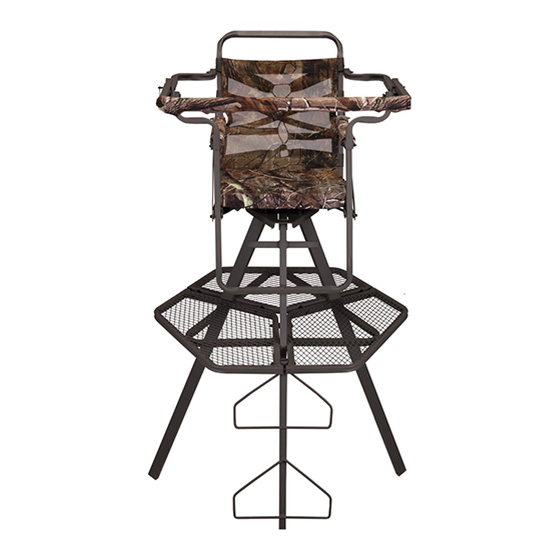
Watchtower Tripod Stand - 12'
SU82099
© 2016 Summit Treestands, LLC | 715 Summit Dr. Decatur, AL 35601
•
DO NOT USE IF YOU DON'T COMPLETELY UNDERSTAND SAFE AND PROPER USE OF THE TREESTAND! WHEN USED HEREIN, "TREESTAND"
INCLUDES TRIPODS, CLIMBING STANDS, FIXED POSITION STAND AND LADDER STANDS. FAILURE TO FOLLOW ALL WRITTEN AND VIDEO
WARNINGS AND INSTRUCTIONS LISTED COULD RESULT IN SERIOUS INJURY OR DEATH! IT IS REQUIRED THAT YOU WATCH AND UNDERSTAND
THE DVD SUPPLIED WITH THIS PRODUCT & THOSE SAFETY WARNINGS AND INSTRUCTIONS POSTED AT: www.summitstands.com/safety-videos
•
WHEN HUNTING FROM A TREESTAND, FALLS CAN OCCUR ANY TIME AFTER LEAVING THE GROUND! ANY FALL CAN CAUSE SERIOUS INJURY
OR DEATH!
•
ALWAYS NOTIFY SOMEONE OF YOUR HUNTING LOCATION IN CASE OF AN EMERGENCY.
•
DO NOT USE THIS STAND IN HIGH WIND CONDITIONS THAT COULD RESULT IN A TIP OVER.
•
IF THERE ARE ANY QUESTIONS OR CONCERNS WITH INSTRUCTIONS, WARNINGS, OR PROPER USE, "STOP" AND CONTACT THE
MANUFACTURER. DO NOT USE UNLESS YOU FULLY UNDERSTAND SAFE AND PROPER USE. MAINTAIN ALL WARNINGS, INSTRUCTIONS, AND
DVD(S) FOR LATER REVIEW AS NEEDED, FOR INSTRUCTION USAGE TO ANYONE BORROWING YOUR STAND OR TO PASS ON WHEN SELLING
THESE ITEMS. USE ALL SAFETY DEVICES PROVIDED WITH YOUR TREESTAND.
•
PRIOR TO EACH USE, INSPECT ALL LADDER SECTIONS TO ENSURE THE SECTIONS ARE NOT SEPARATED. ENSURE THE GROUND BELOW THE
LADDER SECTIONS IS FIRM AND LEVEL.
•
ALL TRIPODS MUST BE ANCHORED TO THE GROUND BY MEANS OF GROUND STAKES. IT IS ADVISABLE TO PURCHASE ADDITIONAL MEANS OF
SECURING THE TRIPOD TO THE GROUND INCLUDING STRAPS OR GROUND ANCHORS. FOLLOW ALL INSTRUCTIONS FROM SUPPLIERS FOR
ANCHORING FREE-STANDING UNITS.
•
ALL TRIPODS SHOULD BE GROUNDED TO THE GROUND BY A LICENSED ELECTRICIAN IN THE EVENT IT IS STRUCK BY LIGHTNING.
•
INSPECT THE TREESTAND PRIOR TO EVERY USE FOR UNDUE WEAR, DEFORMITY, CORROSION OR OTHER DAMAGE. INSPECT ALL STRAPS,
WEBBING AND ROPES FOR FRAYING, RIPS, TEARS, CUTS, UNDUE WEAR OR ANY OTHER TYPE OF DAMAGE. DISCONTINUE USE IMMEDIATELY
IF ANY DAMAGE IS PRESENT.
•
NEVER EXCEED THE MAXIMUM RATED WEIGHT LIMIT OF THIS PRODUCT. THIS LIMIT INCLUDES USER AND ALL GEAR TAKEN TO THE PLATFORM
AREA.
•
MOST FALLS OCCUR DUE TO IMPROPER INSTALLATION OR NOT USING THE PRODUCT AS DIRECTED. ALL SUPPLIED PARTS MUST BE USED,
INCLUDING, BUT NOT LIMITED TO ALL REQUIRED HARDWARE. LADDER SECTIONS CONNECTIONS MUST BE SECURED TOGETHER BY MEANS
OF THE PINS OR BOLTS SUPPLIED. CAREFULLY FOLLOW AND DOUBLE CHECK ALL ASSEMBLY INSTRUCTIONS TO ENSURE THAT YOU HAVE
PROPERLY ASSEMBLED THE PRODUCT. IF YOU HAVE ANY QUESTIONS OR CONCERNS, CONTACT SUMMIT AT 800-353-0634.
•
THE ASSEMBLY AND INSTALLATION OF A TRIPOD STAND REQUIRES A MINIMUM OF FOUR (4) ABLE ADULTS. NEVER ATTEMPT TO ASSEMBLE,
INSTALL, OR REMOVE THIS PRODUCT WITH LESS THAN FOUR (4) ABLE ADULTS PRESENT.
•
REPLACE ALL WEBBING AND CABLES EVERY (2) YEARS OR SOONER IF ANY DAMAGE IS PRESENT INCLUDING, BUT NOT LIMITED TO, FRAYING,
CORROSION, CUTS, TEARS, ABRASIONS, FADING, NICKS, CUTS OR ANY SIGNS THAT THE WEBBING OR CABLES HAVE BEEN FATIGUED OR
STRESSED BY A FALL OR BY ANYTHING INCLUDING BUT NOT LIMITED TO SUPPORTING EXCESS WEIGHT. IF ANY OF THE DAMAGE STATED
ABOVE (OR ANY OTHER TYPE OF DAMAGE NOT LISTED) IS PRESENT, DISCONTINUE USE OF THE PRODUCT IMMEDIATELY!
•
DO NOT USE ANY TREESTAND IF ICE OR SNOW IS PRESENT ON THE PLATFORM OR LADDER SECTIONS.
•
ALWAYS HAVE THREE (3) POINTS OF CONTACT TO THE LADDER WHILE CLIMBING. NEVER CLIMB WITH ANYTHING ON YOUR BACK OR IN YOUR
HANDS WHILE CLIMBING. TAKE YOUR TIME, DO NOT BE IN A HURRY!!
•
THIS PRODUCT MUST BE USED ONLY ON LEVEL GROUND. IF THE GROUND IS SLOPED OR UN-LEVEL, THE STAND MAY NOT BALANCE
CORRECTLY AND COULD RESULT IN A TIP OVER LEADING TO SERIOUS INJURY OR DEATH.
•
PRIOR TO EACH USE INSURE:
•
ALL LADDER SECTIONS ARE NOT SEPARATED.
•
ALL SECTIONS ARE SECURED TOGETHER BY MEANS OF PINS OR BOLTS.
•
THERE ARE NO VISIBLE SIGNS OF CORROSION PRESENT.
•
THERE ARE NO CRACKS IN ANY TUBING.
•
THERE ARE NO CRACKS IN ANY WELDS.
•
THERE ARE NO LOOSE WELD JOINTS.
•
THE BOTTOM LEG SECTION IS ANCHORED TO THE GROUND TO PREVENT MOVEMENT.
IF ANY OF THE CONDITIONS STATED ABOVE ARE NOT MET, DISCONTINUE USE OF THE PRODUCT IMMEDIATELY!
•
IT IS NECESSARY AND VERY IMPORTANT THAT SOMEONE KNOWS YOUR HUNTING LOCATION AND TIME OF RETURN. IT IS ALSO VERY
IMPORTANT THAT YOU CARRY (ON YOUR PERSON) EMERGENCY COMMUNICATION DEVICES SUCH AS A CELL PHONE, TWO-WAY RADIO,
WHISTLE, SIGNAL FLARE OR PREFERABLY A PLD (PERSONAL LOCATOR DEVICE - FCC APPROVED JULY, '03). WHEN TRIGGERED, A PLD WILL
TRANSMIT AN EMERGENCY SIGNAL TO LOCAL RESCUE TEAMS IDENTIFYING YOUR LOCATION VIA SATELLITE GPS COORDINATES. PLD'S MAY
BE PURCHASED AT WILDERNESS OUTFITTERS OR ON THE INTERNET. IF STATED DEVICE(S) IS NOT PRESENT, HUNT FROM THE GROUND!!
PRINTED IN CHINA
PH#: (800) 353-0634 | www.summitstands.com
WARNING
!
FAILURE TO READ AND FOLLOW ALL MANUFACTURER'S
WARNINGS AND INSTRUCTIONS CONSTITUTES A MISUSE OF THIS
PRODUCT AND COULD RESULT IN SERIOUS INJURY OR DEATH!!
Watchtower 12' 82099, 2/2016
Advertisement
Table of Contents

Subscribe to Our Youtube Channel
Related Manuals for Summit Treestands SU82099


Summary of Contents for Summit Treestands SU82099
- Page 1 Watchtower Tripod Stand - 12’ SU82099 WARNING © 2016 Summit Treestands, LLC | 715 Summit Dr. Decatur, AL 35601 PH#: (800) 353-0634 | www.summitstands.com FAILURE TO READ AND FOLLOW ALL MANUFACTURER’S WARNINGS AND INSTRUCTIONS CONSTITUTES A MISUSE OF THIS PRODUCT AND COULD RESULT IN SERIOUS INJURY OR DEATH!! •...
- Page 2 AFTER EACH USE! NEVER ASSUME THAT ANY PART, THAT MAY HAVE BEEN SUBJECTED TO DAMAGE OR WEAR, IS OK FOR USE. STOP USE IMMEDIATELY AND CONTACT SUMMIT TREESTANDS IMMEDIATELY IF YOU HAVE ANY CONCERNS OR SUSPICIONS ABOUT YOUR PRODUCT. •...
- Page 3 (Includes hunter’s weight PLUS weight of all gear carried into the treestand) DO NOT EXCEED THESE WEIGHT LIMITS! 300 lb Rated Stand: SU82099 - Watchtower 12’ THIS TREESTAND IS INTENDED FOR SINGLE PERSON USE ONLY!! STAND / COMPONENT WARNING LABELS...
-
Page 4: Table Of Contents
HARDWARE PACKET CONTENTS PARTS LIST 5/16”-18 HARDWARE LISTED IN THROUGHOUT BOOKLET DESCRIPTION PACKET A PACKET B BOX CONTENTS SU10615 1 3/4” BOLT, 5/16”-18 DESCRIPTION SEAT ASSEMBLY 82072.R20 SEAT BASE 82072.R30 FOOTREST BAR SU10615 2 3/4” BOLT, 5/16”-18 82072.R70 SLIDE BRACKET 82072.R30 SEAT BACK 82072.R40... -
Page 5: Seat Base
TOOLS REQUIRED Tools • 7/16” Wrenches and / or Socket / Ratchet • 1/2” Wrenches and / or Socket / Ratchet - Assembly can be made easier by the use of a powered ratchet or drill with socket adapter (take care not to over tighten when using power tools to assemble) - It is recommended that all bolts be sorted by thread count / length prior to assembly. -
Page 6: Gunrest Upright
SEAT ASSEMBLY (continued) 8. Slide one Gunrest Upright down onto the Footrest Bar as shown in figure 5. GUNREST 9. Next, line up one of the Seat Side Tubes between the Seat Back UPRIGHT and Footrest Bar as shown in figure 6. The Seat Side Tube attaches (PN 82072.R40) over the Gunrest Upright and between the Slide Bracket and Seat Back. -
Page 7: Gunrest Side Tube
2 1/2” BOLTS, WASHER, SEAT ASSEMBLY (continued) 16. Attach the Gunrest Side Tubes next. Line up the front and rear LOCK NUTS holes. Use one Nylon Washer between both joints. Use one 2 1/2” bolt and lock nut at each joint as shown in figure 11. Do not over GUNREST tighten. -
Page 8: Upper Leg
BASE PLATE (continued) ANGLED END 3. Position the two Upper Legs as shown in figure 17. Slide these FACING OUT / legs into the Base Plate and secure with one 1 3/4” bolt and lock nut BOLT HOLE TO per Leg (see figure 18). Leave these bolts hand tight for now. THE INSIDE 1 3/4”... -
Page 9: Upper Leg With Hand Hold
PLATFORM (continued) PLATFORM 3. Attach the last Platform Section next. Slip it over the two exposed SECTION bolts and secure using lock nuts as shown in figure 23. Leave these LOCK NUTS (PN 82072.400) hand tight for now. 4. Position one of the Platform Stand-Offs as shown in figure 24. Slide the stand off between the platform sections. - Page 10 SEAT TO PLATFORM ATTACHMENT Hardware Needed 1. Position the completed Seat Assembly over the Tripod Base 1/4”-20 - 1 1/2” Bolt Steel Washers as shown in figure 29. It may be helpful to have a helper 1/4”-20 - Lock Nut complete this step.
-
Page 11: Coupler Plate
LEG ASSEMBLY / LEG BRACES Hardware Needed 5/16”-18 - 2 3/4” Bolt 1/4”-20 - 1 1/2” Bolt - 12 5/16”-18 - 3 3/4” Bolt 1/4”-20 - Lock Nuts - 12 5/16”-18 - Lock Nuts 1. Carefully lay the completed top section on its side - ladder rungs up as shown in figure 36. -
Page 12: 12' Leg Assembly
LEG ASSEMBLY (continued) 10. Position one of the 12’ Leg Assemblies as shown in figure 42. The oval pre-punched holes MUST be on the far end of the Leg Assembly. These holes are for the Spikes included with this tripod 12’... - Page 13 LEG BRACES (continued) 4. The six Cross Braces will attach next. Start by positioning one Cross Brace as shown in figure 46. This Brace will bolt to the OUTSIDE of the two Brackets, as shown in figure 47 and figure 48. 5.
- Page 14 LEG BRACES (continued) 8. Walk around to the opposite side of the Tripod. Attach one more Cross Brace (in green) to the OUTSIDE of the Bracket and one more Cross Brace (in blue) to the INSIDE of the Bracket. See figure 52. Figure 53 shows the correct placement of braces.
- Page 15 SETUP 1. Find a suitable area to set up the Tripod. Ensure the ground is firm and level. Sloping ground or uneven surfaces will cause instability. This instability could cause the tripod to tilt or shift as you ascend or descend the ladder. 2.
- Page 16 (A) Warranty Summit Treestands, LLC (Summit) warrants to the original retail purchaser that all products manufactured by it are free from defects in material and manufacture at the time of shipment for twelve (12) months from the date of purchase. Summit will repair or replace any part found defective if the unit claimed to be defective shall be returned to Summit, postage prepaid, within the warranty period.
- Page 17 Watchtower Trépied - 12’ SU82099 AVERTISSEMENT © 2016 Summit Treestands, LLC | 715 Summit Dr. Decatur, AL 35601 PH#: (800) 353-0634 | www.summitstands.com NE PAS LIRE ET NE PAS SUIVRE LES AVERTISSEMENTS ET LES INSTRUCTIONS DU MANUFACTURIER CONSTITUE UNE MAUVAISE UTILISATION DU PRODUIT ET PEUT ENTRAÎNER DE SÉRIEUSES BLESSURES OU LA MORT!!
- Page 18 • IL EST NÉCESSAIRE ET TRÈS IMPORTANT QU’UNE AUTRE PERSONNE CONNAISSE VOTRE LIEU DE CHASSE ET L’HEURE DE VOTRE RETOUR. IL EST ÉGALEMENT TRÈS IMPORTANT QUE VOUS AYEZ (EN VOTRE POSSESSION) UN DISPOSITIF DE COMMUNICATION D’URGENCE TEL UN TÉLÉPHONE CÉLLULAIRE, UNE RADIO BIDIRECTIONNELLE, UN SIFFLET, UNE FUSÉE DE SIGNALISATION OU PRÉFÉRABLEMENT UN DLP (DISPOSITIF DE LOCALISATION PERSONNEL - APPROUVÉ...
- Page 19 LIMITE DE POIDS Vous devez également visionné le DVD ci-joint AVANT d’utiliser votre nouveau mirador!! Évalué à 136 KG: LIMITE DE POIDS SU82099 - Watchtower 12’ LIMITE DE POIDS POUR OCCUPATION INDIVIDUELLE 136 KGS. X 1 TOTAL* NE DÉPASSER PAS CETTE LIMITE! (* Inclus tout l’équipement)
-
Page 20: Description
POCHETTE DE LA QUINCAILLERIE LISTE DES PIÈCES 5/16”-18 MATÉRIEL LISTÉ DANS ROUGE DANS LE LIVRET DESCRIPTION PACKET A PACKET B CONTENU DE LA BÔITE SU10615 1 3/4” BOULON, 5/16”-18 DESCRIPTION ASSEMBLAGE DU SIÈGE 82072.R20 BASE DU SIÈGE 82072.R30 BARRE DU REPOSE-PIED SU10615 2 3/4”... - Page 21 OUTILS REQUIS Outils • Clés 7/16 po. et / ou Douille / Rochet • Clés 1/2 po. et / ou Douille / Rochet - L’assemblage peut être facilité avec l’utilisation d’un rochet électrique ou d’une perceuse avec douille (assurez-vous de ne pas serrer trop fort lors de l’assemblage avec des outils électriques).
- Page 22 ASSEMBLAGE DU SIÈGE (suite) 8. Glissez un montant droit de l’appui-arme sur la barre du repose- MONTANT pied tel qu’illustré à la figure 5. DROIT DE 9. Ensuite, alignez un des tubes latéraux du siège entre le dossier du L’APPUI-ARME siège et la barre du repose-pied tel qu’illustré...
- Page 23 2 1/2” BOULON, RONDELLE ASSEMBLAGE DU SIÈGE (suite) 16. Attachez ensuite les tubes latéraux de l’appui-arme. Alignez PLATE DE NYLON, ÉCROU les trous avant et arrière. Utilisez une rondelle de nylon entre les DE BLOCAGES deux joints. Utilisez un boulon de 2 1/2 po. et un écrou de blocage à...
- Page 24 PLAQUE DE SOUTIEN (suite) LE BOUT EN ANGLE 3. Placez les deux pattes supérieures tel qu’illustré à la figure 17. FAIT FACE VERS Glissez ces pattes sur la plaque de soutien et sécurisez avec un boulon L’EXTÉRIEUR / LE TROU DU BOULON de 1 ¾...
- Page 25 ASSEMBLAGE DE PLATEFORME (suite) 3. Attachez ensuite la section de la plateforme restante. Glissez- LA PLATEFORME la par-dessus les deux boulons exposés et sécurisez le tout à l’aid ÉCROU DE BLOCAGES (PN 82072.400) d’écrous de blocage tel qu’illustré à la figure 23. Serrez ceci avec vos mains seulement pour le moment.
- Page 26 FIXATION DU SUPPORT DU SIÈGE Matériel Nécessaire 1. Placez le support du siège complété sur la base du trépied tel 1/4”-20 - 1 1/2” Boulon Rondelle Plate D’Acier qu’illustré à la figure 29. Il est préférable d’avoir quelqu’un pour 1/4”-20 - Écrou de blocage - 4 vous aidr à...
- Page 27 ASSEMBLAGE DE LA PATTE SUPÉRIEURE / SUPPORT DES PATTES SUPÉRIEURES Matériel Nécessaire 5/16”-18 - 2 3/4” Boulon - 8 1/4”-20 - 1 1/2” Boulon - 12 5/16”-18 - 3 3/4” Boulon - 1 1/4”-20 - Écrou de blocage - 12 5/16”-18 - Écrou de blocage - 9 1.
- Page 28 ASSEMBLAGE DE PATTE (suite) 10. Placez un des assemblage de la patte de 12 pieds tel qu’illustré ASSEMBLAGE DE à la figure 42. Les trous de forme ovale perforés préalablement DOIVENT être sur le bout éloigné de la patte. Ces trous sont pour les LA PATTE DE 12 pointes fournies avec ce trépied.
- Page 29 APPUIS DE PATTE (suite) 4. Les six appuis latéraux supérieurs sont joints ensuite. Commencez en plaçant un appui latéral tel qu’illustré à la figure 46. Cet appui se fixera à L’EXTÉRIEUR des deux supports, tel qu’illustré aux figures 47 et 48. 5.
- Page 30 APPUIS DE PATTE (suite) 8. Faites le tour du côté opposé du trépied. Installez un autre appui latéral supérieur (en vert) à L’EXTÉRIEUR du support et un autre appui latéral bleu) à L’INTÉRIEUR du support. Voir la figure 52. La figure 53 démontre la façon correcte de placer les supports.
- Page 31 INSTALLATION 1. Trouvez un emplacement propice pour installer le trépied. Assurez-vous que le sol est ferme et à niveau. Un sol en pente ou inégal causera de l’instabilité. Cette instabilité peut faire basculer ou déplacer le trépied lors de l’ascension ou de la descente dans l’échelle. 2.
- Page 32 (A) Garantie La compagnie Summit Treestands, LLC (Summit) garantie à l’acheteur original que tous ses produits manufacturés sont sans défauts du matériel et de fabrication lors de l’expédition et ce pour douze (12) mois à partir de la date d’achat. Summit remplacera toute pièce défectueuse si le module soi-disant défectueux est retourné...
Need help?
Do you have a question about the SU82099 and is the answer not in the manual?
Questions and answers