Table of Contents
Advertisement
INSTALLATION, OPERATING
ELECTRONIC CITY SOFT PLUS SYSTEM
7-LESDCATS-75B
7-LESDCATS-100B
7-LESDCATS-150B
7-LESDCATS-200B
7-LESDNS-75B
7-LESDNS-100B
7-LESDNS-150B
7-LESDNS-200B
Congratulations on purchasing your new Lancaster Water Conditioner. This unit is designed to give
you many years of trouble free service. When installed in accordance with the following instructions
and if given reasonable care, clear-soft water will be the result. For servicing and future inspection
purposes, please file this booklet with your important documents.
In the event that you need assistance for servicing your water conditioner, please first contact the
professional contractor who installed the system.
AND SERVICE MANUAL
PLATINUM LINE LES
WITH THE LESCV1 VALVE
PAGE 1
Advertisement
Table of Contents

Related Manuals for Lancaster PLATINUM LINE LES X Factor Series


Summary of Contents for Lancaster PLATINUM LINE LES X Factor Series
- Page 1 7-LESDNS-150B 7-LESDNS-200B Congratulations on purchasing your new Lancaster Water Conditioner. This unit is designed to give you many years of trouble free service. When installed in accordance with the following instructions and if given reasonable care, clear-soft water will be the result. For servicing and future inspection purposes, please file this booklet with your important documents.
-
Page 2: Table Of Contents
TABLE OF CONTENTS Job Specifications ......................... 2 Pre-Installation Review ......................... 3 General Installation and Service Warnings .................. 3 Bypass Valve Operation ....................... 4 Installation Instructions, Diagrams ....................5, 6 Placing System into Service ......................7 Set Time of Day ..........................7 Adjust Hardness, Days Between Regenerations or Time of Regeneration ........ -
Page 3: Pre-Installation Review
GENERAL INSTALLATION PRE-INSTALLATION AND SERVICE WARNINGS REVIEW The control valve, fitting and/or bypass are designed to WATER QUALITY: If sand or sediment is present in the accommodate minor plumbing misalignments but are water supply, a sediment filter should be installed ahead not designed to support the weight of a system or the of the water conditioner. -
Page 4: Bypass Valve Operation
BYPASS VALVE The bypass valve is typically used to isolate the control valve from the plumbing system’s water pressure in order to perform control valve repairs or maintenance. The X-Factor bypass valve is particularly unique in the water treatment industry due to its versatility and state of the art design features. -
Page 5: Installation Instructions, Diagrams
INSTALLATION INSTRUCTIONS (All electrical & plumbing should be done in accordance to all local codes) 1. Place the system where you want to install it, making 8. Connect the brine line polytubing found with the brine sure it is on a clean, level and firm base. tank to the brine connection on the control valve. - Page 6 MINIMUM 10 FEET BETWEEN WATER CONDITIONER OUTLET OUTSIDE MINIMUM 10 FEET BETWEEN WATER HEATER INLET OUTSIDE WATER CONDITIONER OUTLET WATER HEATER INLET LOCATE WATER CONDITIONER CLOSE TO A DRAIN. COLD BYPASS PLUMBING AVOID OVERHEAD DRAIN LINES IF POSSIBLE TO LOCATE WATER CONDITIONER CLOSE TO A DRAIN. COLD RECOMMENDED PREVENT BACK PRESSURE ON BRINE INJECTOR.
-
Page 7: Placing System Into Service
PLACING THE CITY SOFT PLUS INTO SERVICE PLACING UNIT INTO SERVICE: Make sure inlet and outlet valves are to their closed positions. If using optional bypass, place in bypass position. Turn on main water supply. Open a cold water faucet. This will clear the lines of any debris (solder, pipe dope, etc.) that may be in the line. -
Page 8: Adjust Hardness, Days Between Regenerations Or Time Of Regeneration
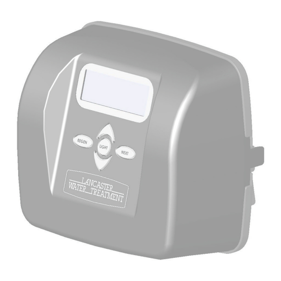
ADJUST HARDNESS, DAYS BETWEEN REGENERATIONS, OR TIME OF REGENERATION STEP 1 STEP 1 - Press simultaneously for 3 seconds to access Installer Display Settings. NEXT STEP 2 – Hardness: Set the amount of hardness in grains of hardness as calcium carbonate per STEP 2 gallon using the buttons. -
Page 9: Parts Diagrams
OUTSIDE LOCATE WATER CONDITIONER CLOSE TO A DRAIN. MINERAL TANK ASSEMBLY BYPASS PLUMBING AVOID OVERHEAD DRAIN LINES IF POSSIBLE TO RECOMMENDED PREVENT BACK PRESSURE ON BRINE INJECTOR. OPTIONAL BP2000 IF OVERHEAD DRAIN LINE IS USED AND EXCEEDS Item BYPASS VALVE 5 FEET ABOVE CONNECTION ON CONTROL VALVE Order No. - Page 10 Output Current 500 mA When replacing the battery, align Correct Battery replacement positives and push down to fully seat. Battery is 3 volt lithium coin Orientation cell type 2032. WS1TC & WS1.25 TC Manual Page 13 FRONT COVER AND DRIVE ASSEMBLY WS1TC Drive Cap Assembly, DownÁ...
- Page 11 V3182 WS1 RFC V4144-01 Elbow 3/8 Liquifi t Asy w/RFC Not Shown V3552 WS1 Brine Elbow Asy w/RFC REFILL FLOW CONTROL ASSEMBLY Not Shown H4650 Elbow ½” with nut and insert *Assembly includes V3182 WS1 (0.5 gpm) RFC. Drawing No.
- Page 12 DRAIN LINE - 3/4” Order No. Description H4615 Elbow Locking Clip V3194 Polytube insert 5/8 Option V3192 Nut ¾ Drain Elbow Option V3158 Drain Elbow ¾ Male V3163 O-ring 019 V3159 DLFC Retainer Assy V3162-007 DLFC 0.7 gpm for ¾ ...
- Page 13 BYPASS VALVE (Order No. BP2000) Drawing No. Order No. Description V3151 Nut 1” Quick Connect V3150 Split Ring V3105 O-Ring 215 V3145 Bypass 1” Rotor V3146 Bypass Cap V3147 Bypass Handle V3148 Bypass Rotor Seal Retainer V3152 O-ring 135...
- Page 14 OPTIONAL INSTALLATION FITTING ASSEMBLIES Order No: V3007-03 Order No: V3007-01 Order No: V3007-02 Description: Fitting ¾” Brass Sweat Assembly Description: Fitting ¾” & 1” PVC Solvent 90° Description: Fitting 1” Brass Sweat Assembly Assembly Drawing Drawing Order Order No. Description Quantity Description Quantity...
-
Page 15: Service Instructions
SERVICE INSTRUCTIONS DRIVE ASSEMBLY (refer to pages 10 for diagrams): Remove the valve cover to access the drive assembly. Disconnect the power source plug (black wire) from the PC board prior to disconnecting the motor or water meter plugs from the PC board. The power source plug connects to the four-pin jack. The motor plug connects to the two-pin jack on the left-hand side of the PC board. - Page 16 DRIVE CAP ASSEMBLY, MAIN PISTON AND REGENERANT PISTON (refer to pages 10 for diagrams): The drive assembly must be removed to access the drive cap assembly. The drive cap assembly must be removed to access the piston(s). The drive cap assembly is threaded into the control valve body and seals with an o-ring. To remove the drive cap assembly use the special plastic service spanner wrench (see page 13) or insert a ¼”...
- Page 17 SPACER STACK ASSEMBLY (refer to pages 10 for diagrams): To access the spacer stack assembly remove the drive assembly, drive cap assembly and piston. The spacer stack assembly can be removed easily without tools by using thumb and forefinger. Inspect the black o-rings and clear lip seals for wear or damage.
-
Page 18: Troubleshooting
TROUBLESHOOTING PROCEDURES PROBLEM POSSIBLE CAUSE SOLUTION a. Transformer unplugged a. Connect power 1. Timer does not display time of b. No electric power at outlet b. Repair outlet or use working outlet day. c. Defective transformer c. Replace transformer d. Defective PC board d. - Page 19 NOTES PAGE 19...
- Page 20 A DIVISION OF C-B TOOL CO. 1340 MANHEIM PIKE ● LANCASTER PA 17601-3196 ● TEL:717-397-3521 ● FAX: 717-392-0266 www.lancasterwatertreatment.com ● E-mail: info@lancasterpump.com 11/19 PAGE 20...
Need help?
Do you have a question about the PLATINUM LINE LES X Factor Series and is the answer not in the manual?
Questions and answers