Advertisement
INSTALLATION, OPERATING AND
FEATURING THE LETCV1F VALVE
COLOR, TASTE, ODOR
7-LETCT-1B
7-LETCT-2B
7-LETCT-3B
IRON FILTER
7-LETIM-1B
7-LETIM-2B
7-LETIM-3B
SEDIMENT/TURBIDITY
7-LETST-1B
7-LETST-2B
7-LETST-3B
Congratulations on purchasing your new Lancaster Water Filter. This unit is designed to give you
many years of trouble free service. For servicing and future inspection purposes, please file this
booklet with your important documents.
In the event that you need assistance for servicing your water filter, please first contact the
professional contractor who installed the system.
SERVICE MANUAL
BRONZE LINE LET
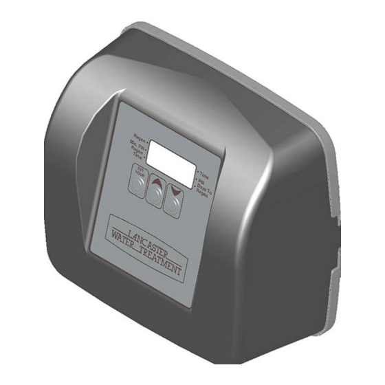
ELECTRONIC WATER FILTER
TIME CLOCK MODEL
ACID NEUTRALIZERS
7-LETDAN-1B
7-LETDAN-1.5B
7-LETDAN-2B
7-LETDAN-3B
F I L T E R
PAGE 1
Advertisement
Table of Contents

Related Manuals for Lancaster 7-LETCT-1B


Summary of Contents for Lancaster 7-LETCT-1B
- Page 1 7-LETST-1B 7-LETST-2B 7-LETST-3B Congratulations on purchasing your new Lancaster Water Filter. This unit is designed to give you many years of trouble free service. For servicing and future inspection purposes, please file this booklet with your important documents. In the event that you need assistance for servicing your water filter, please first contact the professional contractor who installed the system.
-
Page 2: Operating Parameters
OPERATING PARAMETERS Minimum / Maximum Operating Pressures 20 psi (138 kPa) - 125 psi (862 kPa) Minimum / Maximum Operating Temperatures 40°F (4°C) - 110°F (38°C) Current Draw & Voltage 0.5 Amperes - 110 Volts Other Options Available GENERAL WARNINGS The control valve, fittings and/or bypass are designed to accommodate minor plumbing misalignments but are not designed to support the weight of a system or the plumbing. -
Page 3: Installation
A8007 BIRM - (1) 7-LETIM-2B FG1348, 13 X 48 A8007 BIRM - (2) 7-LETIM-3B FG1465, 14 X 65 A8007 BIRM - (3) 7-LETCT-1B FG1044,10 X 44 A8009 CARBON - (1) 7-LETCT-2B FG1348, 13 X 48 A8009 CARBON - (2) 7-LETCT-3B... -
Page 4: Set Time Of Day
INSTALLATION CONT. • Replace the control valve making sure that the distributor tube is inserted into the center hole of the bottom of the control valve. • Complete plumbing. • Place the bypass valve in “BYPASS OPERATION”. (Figure 1) • Plug the transformer into a 120V uninterrupted receptacle. - Page 5 SET REGENERATION TIME AND DAYS BETWEEN BACKWASHES Page 8 WS1TC & WS1.25 TC Manual STEP 1: From normal mode, press SET HOUR + ▲ buttons simultaneously for 3 seconds and Installer Displays & Settings (1-99 Days Between Regeneration Option) STEP 1ID release.
-
Page 6: Drive Assembly
ADDITIONAL PROGRAMMING INFORMATION AVAILABLE FROM LANCASTER WATER TREATMENT UPON REQUEST. INCLUDES: 7-DAY OPTION, REGENERATION CYCLES, TIMES AND 50 Hz. SERVICE INSTRUCTIONS ACID NEUTRALIZERS, (7-LETDAN-): Mineral used: Calcite. Calcite will dissolve in proportion to the amount of acid in the raw water. The amount of calcite in the tank should be monitored and replaced periodically. A tank with a dome plug is provided so that calcite may be added without removing the control valve. - Page 7 There are three drive gears held in place by the drive gear cover. All three drive gears are the same size. A reflective coating is applied to the gears. As the center drive gear turns a light shines on the coating and a light sensing diode determines if a light pulse was returned.
-
Page 8: Spacer Stack Assembly
DRIVE CAP ASSEMBLY, MAIN PISTON AND REGENERANT PISTON: The drive gears turn the main gear of the drive cap assembly, which moves the piston. The screw-driven, horizontally moving piston stops at specific positions to direct the flow of water to backwash, regenerate, rinse or refill. The PC board determines the position of the piston by counting pulses produced when the piston is moved. -
Page 9: Bypass Valve
REFILL FLOW CONTROL ASSEMBLY OR REFILL PORT PLUG: The refill flow control assembly consists of a refill flow elbow, refill flow control retainer assembly, refill flow control, polytube insert and nut assembly. The refill flow control retainer fits in the refill elbow. The refill flow control retainer houses the refill flow control which controls the flow rate when the regenerant tank is being refilled. - Page 10 OPTIONAL MAINTENANCE WRENCH V3193 Although no tools are necessary to assemble the valve, the optional maintenance wrench (shown in various positions on the valve) may be purchased to aid in assembly or disassembly. Loosens Drain Nut In Polytube Applications Loosens Injector And Bypass Caps Loosens Quick Connect Nuts...
- Page 11 PARTS V3007 1” PVC Male NPT Elbow Assembly Standard Item No. Quantity Part No. Description V3151 Nut 1” Quick Connect V3150 Split Ring V3105...
- Page 12 V3186EU WS1 AC ADAPTER 220-240V-12V EU Not Shown V3186UK WS1 AC ADAPTER 220-240V-12V UK V3186-01 WS1 AC ADAPTER CORD ONLY * Drawing number parts 2 through 6 may be purchased as a complete assembly, part V3002. FRONT COVER AND DRIVE ASSEMBLY When replacing the battery, align Correct positives and push down to fully seat.
- Page 13 WS1 & WS1.25 Drawings & Service Manual Page Drain Line – 3/4” Drawing No. Order No. Description Quantity METER PLUG H4615 Elbow Locking Clip PKP10TS8-BULK Polytube insert 5/8 Option Item No. Quantity Part No. Description V3192 WS1 Nut ¾ Drain Elbow Option V3158-01 WS1 Drain Elbow ¾...
-
Page 14: Troubleshooting
▲ and ▼ b. Set-up error b. Check control valve set-up buttons are depressed. procedure A DIVISION OF C-B TOOL CO. 1340 MANHEIM PIKE ● LANCASTER PA 17601-3196 ● TEL:717-397-3521 ● FAX: 717-392-0266 4/16 PAGE 14 www.lancasterwatertreatment.com ● E-mail: info@lancasterpump.com...
Need help?
Do you have a question about the 7-LETCT-1B and is the answer not in the manual?
Questions and answers
how many minutes will it regen , what does c1 mean what does c4 mean?