Table of Contents
Advertisement
Quick Links
P/N 06-237058-001
February 2012
Intelligent Fire Alarm-Suppression
FM Approvals
Project ID 3038124
Installation, Operation, and
Maintenance Manual
STATE FIRE MARSHAL
UL Listing File
No. S2422
Certificate of Approval
ARIES NETLink
New York City Fire Department
Certificate of Approval
California Office of
State Fire Marshal
No. 7165-1076:0195
Control Unit
No. 6092
TM
Advertisement
Table of Contents

Related Manuals for Kidde Fire Systems ARIES NETLink


Summary of Contents for Kidde Fire Systems ARIES NETLink
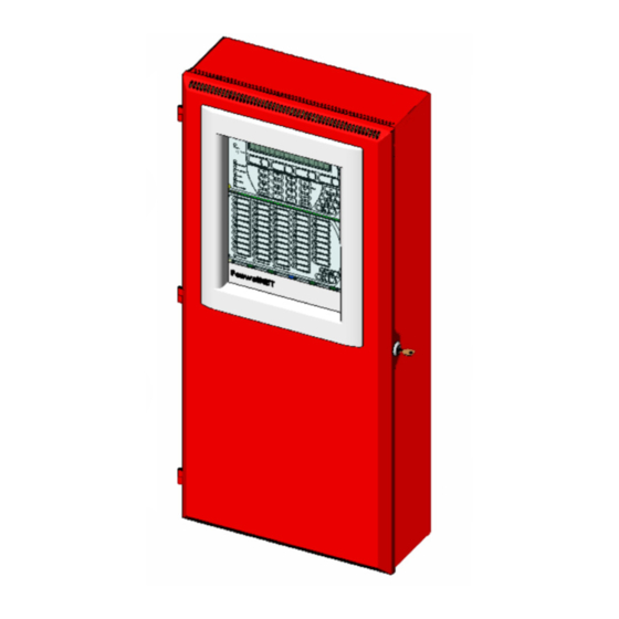
- Page 1 P/N 06-237058-001 February 2012 ARIES NETLink Intelligent Fire Alarm-Suppression Control Unit Installation, Operation, and Maintenance Manual New York City Fire Department Certificate of Approval No. 6092 STATE FIRE MARSHAL FM Approvals California Office of UL Listing File Project ID 3038124 State Fire Marshal No.
- Page 3 NEC, relevant NFPA and local codes but also trained and qualified by Kidde-Fenwal, Inc. Kidde-Fenwal, Inc. is a manufacturer of the components that make up the ARIES NETLink system, and may not have the opportunity to visit the sites where the product is installed or intended to be installed.
-
Page 4: Terms And Abbreviations
TERMS AND ABBREVIATIONS °C °Centigrade LCD: Liquid Crystal Display °F °Farenheit LED: Light Emitting Diode Ampere Main Controller Board Alternating Current NAC: Notification Appliance Circuit ADA: Americans with Disabilities Act N.C.: Normally Closed Ampere Hour NEC: National Electrical Code AHJ: Authority Having Jurisdiction NFPA: National Fire Protection Association... -
Page 5: Safety Summary
SAFETY SUMMARY WARNING AND CAUTION DEFINITIONS This section defines the safety conventions used throughout this manual (“WARNING” and “CAUTION”). Review the definitions below to familiarize yourself with what these conventions mean and why and when they are used. Indicates an imminently hazardous situation which, if not avoided, could result in death, serious bodily injury and/or property damage. - Page 6 Any communication wiring which exits the building or facility should not be routed to or located inside the same conduit as the AC power. Follow the instructions in this manual. These instructions must be followed to avoid damage to the control unit and associated equipment.
- Page 7 GENERAL PRECAUTIONS The following general safety precautions are to be observed at all times: All electrical components associated with equipment shall be installed and grounded in accordance with NEC and local regulatory requirements. Special precautionary measures are essential to prevent applying power to equipment at any time maintenance work is in progress.
- Page 8 Note: The following notice applies to the Digital Alarm Communicator Transmitter (DACT) card (P/N 76-800015-001). NOTICE FCC Part 68 Information - Applies to DACT Options This equipment complies with Part 68 of the Federal Communication Commission (FCC) rules. This unit bears a label which contains, among other information, the FCC registration number and ringer equivalence number (REN) for this equipment.
-
Page 9: Table Of Contents
Table of Contents TABLE OF CONTENTS Foreword ..........................i Terms and Abbreviations ....................ii Safety Summary ......................... iii Table of Contents........................ vii List of Figures........................xiii List of Tables ........................xvii CHAPTER 1 GENERAL INFORMATION Introduction......................1-1 Listings and Approvals ................... 1-1 Codes and Standards.................... -
Page 10: Table Of Contents
Table of Contents TABLE OF CONTENTS (CONT.) CHAPTER 2 INSTALLATION Introduction ......................2-1 Preparing for Installation..................2-1 2-2.1 Unpacking the System .....................2-1 2-2.2 Materials/Tools Required ..................2-2 2-2.3 Determining Wall Location ..................2-2 2-2.4 Removing Knockouts From Enclosure ..............2-2 2-2.5 Installing Conduit....................2-3 2-2.6 Installing Electrical Boxes ..................2-3 Overview of Installation Steps..................2-3 2-3.1 Step One: Shut Off AC Power ..................2-3... - Page 11 Levels of Security ....................4-7 4-8.2 Default Passwords ....................4-8 4-8.3 Entering Passwords ....................4-8 System Startup Procedure ..................4-8 4-9.1 Preliminary Procedures ..................4-8 4-9.2 Initial Power-Up ...................... 4-9 4-10 ARIES NETLink System Operation Overview ............4-12 P/N 06-237058-001 February 2012...
- Page 12 Table of Contents TABLE OF CONTENTS (CONT.) 4-10.1 Normal Operation ....................4-12 4-10.2 Trouble State ......................4-12 4-10.3 Alarm State ......................4-14 4-10.4 Supervisory State ....................4-19 4-10.5 Pre-Alarm State .......................4-20 4-10.6 Concurrent States ....................4-22 CHAPTER 5 NETWORKING Network System Operation..................5-1 Communications .....................5-3 Network Event Broadcasts ..................5-3 Operator Control .....................5-3 Event Recording ......................5-4 Event Output Control (EOC)..................5-4...
- Page 13 Table of Contents TABLE OF CONTENTS (CONT.) APPENDIX A— Battery and Power Supply Calculations ..............A-1 APPENDIX B— Wiring Requirements for ARIES NETLink Signaling Line Circuit......B-1 APPENDIX C— List of Agency Listed Compatible Devices ...............C-1 APPENDIX D— FM Rules for Preaction/Deluge Systems ..............D-1 APPENDIX E—...
- Page 14 Table of Contents THIS PAGE INTENTIONALLY LEFT BLANK. February 2012 P/N 06-237058-001...
-
Page 15: List Of Figures
LIST OF FIGURES Figure Name Page Number Full ARIES NETLink Fire Suppression System Applications ............ 1-3 Illustration of Typical 3-Tiered Main Enclosure Configurations..........1-6 Illustration of Typical 2-Tiered Main Enclosure Configurations..........1-7 Large Expansion Enclosure (a) and Small Expansion Enclosure (b)......... 1-7 Illustration of Remote Enclosure .................... - Page 16 ARIES NETLink Isolate Menu Functions (Cont’d - Fig. 4 of 4)...........3-11 3-14 ARIES NETLink List Menu Functions (Fig. 1 of 5) ..............3-12 3-15 ARIES NETLink List Menu Functions (Cont’d - Fig. 2 of 5) ............3-14 3-16 ARIES NETLink List Menu Functions (Cont’d - Fig. 3 of 5) ............3-15 3-17 ARIES NETLink List Menu Functions (Cont’d - Fig.
- Page 17 4-38 Typical Multiple Level-2 Event-Type Display................4-26 4-39 Lower-Level-Events-Buffer-Full Message ................... 4-27 Typical Networked ARIES NETLink System ................5-2 Network Node Prompt ......................5-5 Top-level Menu Selections ......................5-5 Group 0 Networked Control Unit Interactions ................5-7 Processing Group 0 Networked Control Unit Interactions ............5-9 Network Normal Message Display.....................
- Page 18 Location of knockouts (b) ......................E-4 An Example of a Typical ARIES NETLink Wiring Scenario ............E-5 An Example of a Typical ARIES NETLink Wiring Scenario - MCB Opened....... E-6 An Illustration of Suggested Methods to Dress Wires ............... E-7 3-Tiered Canadian Application Enclosures (shown with Enlosure Door removed) ....F-1...
- Page 19 Operator Control Keys and Their Functions ................4-3 System Status LEDs and Functions..................4-6 LCD Panel System Status Messages..................4-7 Progressive Alarm States of a ARIES NETLink System............. 4-23 Priority Levels for Different Types of Concurrent Events ............4-24 Available Standby Batteries ...................... 6-2 Testing Frequency ........................
- Page 20 List of Tables THIS PAGE INTENTIONALLY LEFT BLANK. February 2012 xviii P/N 06-237058-001...
-
Page 21: General Information
Unit (hereinafter referred to as the “ARIES NETLink”). LISTINGS AND APPROVALS The ARIES NETLink basic control unit is designed to meet the requirements of the agencies shown in Table 1-1 for system classifications as described in NFPA 72 Standard “National Fire Alarm and Signaling Code,”... -
Page 22: Suppression System Standards
General Information 1-3.1 Suppression System Standards The ARIES NETLink control unit is designed for the control and activation of suppression systems listed in Table 1-2 , which the designer/installer should be familiar with. Table 1-2. Listed/Approved Suppression Systems Application Applicable NFPA Standard... -
Page 23: System Description
General Information SYSTEM DESCRIPTION The ARIES NETLink system is an intelligent control panel which coordinates and monitors the varied components of a protected-premises fire suppression system and/or fire alarm system. For each protected zone, the ARIES NETLink system can provide: •... -
Page 24: System Components
Remote Configuration Software (for control unit access/configuration from user-supplied PC) SYSTEM ENCLOSURE TYPES The ARIES NETLink control unit enclosure is designed to house all of the standard features of the control unit; expanded systems may require additional enclosures. Two different sizes of the enclosure are available (specified at time of order): •... -
Page 25: 1-7.1 Enclosure Features
General Information 1-7.1 Enclosure Features • Surface Mountable or Semi-Flush Mountable: The enclosure may be easily wall mounted with provided hardware. Refer to Chapter 2, Section 2-4.1 for complete instructions on wall mounting. The enclosure may optionally be semi-flush mounted between standard 16-in. spaced wall studs with provided hardware. - Page 26 General Information 1-7.1.1 3-TIERED MAIN ENCLOSURE Guidelines for internal configuration of the 3-Tiered Main Enclosure are listed below: • Top Tier: Always reserved for the Power Supply Unit/Power Management (PMU) Board and Main Controller Board (MCB) with keypad/display. The System Enclosure door is designed for the LCD Display to show through the window at this location.
- Page 27 1-7.1.3 EXPANSION ENCLOSURES The ARIES NETLink system is capable of substantial expansion in its total number of add-on cards, Power Supply/PMU Assemblies and batteries. The illustrations below demonstrate available ways of expanding the system. Figure 1-4a shows the large Expansion Enclosure with a power supply/PMU Assembly and two expansion card cages.
- Page 28 Main or Expansion Enclosure(s). The NEMA-1 Large Capacity Battery Cabinet is constructed of the same cold-rolled steel as the other available ARIES NETLink enclosures and is painted red. The Large Capacity Battery Cabinet door is hinged on the left and includes the same lock and key used with the ARIES NETLink enclosures.
-
Page 29: Keypad And Display
The built-in keypad and display is the physical means by which an operator and/or installer performs system functions, enters the security password, navigates the system menus, configures and tests the entire ARIES NETLink system. Refer to Chapters 3 and 4 for complete instructions on how to operate the system using the keypad/display. -
Page 30: Main Controller Board (Mcb)
(CPU) and all of the primary circuits. The MCB is the heart of the system, controlling the operation and supervision of all the system modules and software within the ARIES NETLink system. It receives loop device data, processes the data based on pre-programmed instructions and transmits output commands to the output modules, field devices and display(s). -
Page 31: Main Controller Board Features
• Ground Fault indication: A Ground Fault can be identified to a single circuit (LED indicator lights on the front display). Refer to Section 1-13 for information on expanding the functionality of the ARIES NETLink system with add-on cards. 1-10... -
Page 32: 1-10.1 Power Supply Units
An AC-to-DC switching power supply unit provides a total filtered output of 5.4 A @ 27 Vdc to support the basic ARIES NETLink system and its associated devices and to charge standby batteries. The power supply unit is user-configurable for either 120 Vac or 220/ 240 Vac, 50/60 Hz line voltage (switch located on side of power supply). -
Page 33: Batteries
10-minute alarm period. Refer to Appendix A, Battery and Power Supply Calculations to calculate required battery capacity and standby times. The ARIES NETLink software includes an optional Battery Monitoring Mode which can track battery lifetime from the original install date and sound an audible signal on the replacement due date. -
Page 34: Expansion Card Cage
1-12 EXPANSION CARD CAGE The expandable and flexible nature of the ARIES NETLink system is facilitated by the Expansion Card Cage, where an Expansion Card can be easily plugged into a backplane connector. The Expansion Card Cage is a metal frame which supports and secures a maximum of six Expansion Cards. - Page 35 General Information Expansion Card Backplane Connectors (6) Figure 1-11. ARIES NETLink Expansion Backplane The Expansion Backplane interfaces to the Main Controller Board and Power Supply Assembly via two dedicated connectors: System Power IN (J9) and Communications IN (J10). • The System Power IN connects +24 Vdc power to all six Expansion Card connectors on the backplane.
-
Page 36: Optional Expansion Cards
An Expansion Card Cage contains a total of six Expansion Card slots. A fully expanded ARIES NETLink system can include a total of four Expansion Card Cages. A fully expanded ARIES NETLink system (24 available slots) can include the total number of Expansion Cards listed below: •... - Page 37 Adding a Release/Notification Appliance Circuit Appliance (R-NAC) (R-NAC) Expansion Card increases the functional Circuit Card capacity of the ARIES NETLink system by expanding the number of available signal/releasing circuits to control fire suppression or notification devices. These combination Release/Notification Appliance...
- Page 38 The City Tie Expansion Card occupies a single slot in the Card Cage and plugs directly into the backplane. +24 Vdc power is supplied via the backplane connector. An ARIES NETLink system can include only one City Tie Card. Refer to Figure 2-33 in Chapter 2, “Installation”...
- Page 39 Cage and plugs directly into the backplane. + 24 Vdc power is supplied via the backplane connector. Refer to Figure 2-34 in An ARIES NETLink system can include only one Chapter 2, “Installation” for a wiring diagram for DACT Card.
- Page 40 Illustration Network Interface Card The Network Interface Card is necessary to combine (NIC) up to 64 ARIES NETLink control units into an integrated, peer-to-peer network for annunciation, event output control, and operator intervention. The NIC regenerates and boosts network communications between ARIES NETLink units and electrically isolates the networked control units from each other.
-
Page 41: Optional Remote Devices
ICM Card or modbus clients. Refer to Section 2-11.3 in Chapter 2, Installation, for a list of recommended printer models. 1-14.1.1 OPTIONAL CONFIGURATION VIA REMOTE COMPUTER The ARIES NETLink control unit may be configured remotely from a PC connected to one of the MCB RS232 ports, if desired. 1-14.1.2 OPTIONAL MONITORING VIA INTERNET The ARIES NETLink system may be remotely monitored by means of the Internet, if desired, by using an Internet Communication Module connected to one of the MCB RS232 ports. -
Page 42: 1-14.2 Remote Devices Using Rs485 Bus To Mcb
1-14.2 Remote Devices Using RS485 Bus to MCB The ARIES NETLink system’s Main Controller Board includes an RS485 bus which can communicate with the following remote devices: • Remote LED Annunciator Module (R-LAM) • Remote Display Control Module (RDCM) •... - Page 43 ATM SERIES DRIVER MODULES The ATM Series Driver Modules support the use of third-party graphical annunciators and large numbers of auxiliary relays with the ARIES NETLink. Refer to Figure 1-14 below for an outline of the ATM Series Driver Module.
- Page 44 The Fiber Optic Converter Module (FOCM) consists of a bi-directional, externally-powered unit mounted inside a 13 x 7-1/2 x 2 in. enclosure. One of these is required at both interconnected ARIES NETLink control units for a single communication channel.
-
Page 45: Signaling Line Circuit (Slc) Devices And Modules
SmartOne Devices The ARIES NETLink supports the SmartOne Series of intelligent smoke and heat detectors. These detectors have their own data transceivers, micro-controllers, micro-controller memory, and algorithms that allow the detectors to determine whether a normal, pre-alarm, alarm, or trouble condition exists at their monitoring locations. -
Page 46: High Sensitivity Smoke Detectors
1-16 HIGH SENSITIVITY SMOKE DETECTORS Table 1-5. Supported High Sensitivity Smoke Detectors The ORION XT High Sensitivity Smoke Detector is ® ORION XT designed early warning smoke detection applications such as telecommunications facilities, data processing rooms, museum, warehouses and cleanrooms. The ORION XT consists of a laser particle counter detector head, a high efficiency fan module and a termination board. -
Page 47: Smartone Addressable Modules
Table 1-5. Supported High Sensitivity Smoke Detectors AIR-Intelligence The AIR-Intelligence ASD-640 is identical to the ASD-640 / ASD-160H detector but offers protection for an even larger air sampling pipe network up to 656 feet (200 AIR-Intelligence meters) total. Command Module An ASD-640 can be connected to the Signaling Line Circuit using an Addressable Protocol Interface Card (APIC), P/N 74-333001-001, which mounts... - Page 48 INSTRUCTIONS P/N 06-235717-001 INSTRUCTIONS P/N 06-235717-001 INSTRUCTIONS P/N 06-235717-001 Model ASM the ARIES NETLink’s SLC. The ASM is supplied PC LINE TERMINALS - POWER LIMITED PC LINE TERMINALS - POWER LIMITED ALL OTHERS - POWER LIMITED ALL OTHERS - POWER LIMITED...
- Page 49 Manufacturer Part Number Multi-Zone Power Supply Assembly Kidde 89-300020-001 24 VDC, 2A Auxiliary Power Outputs located Kidde on the ARIES NETLink PMU Board 24Vdc, 3A Power Supply, red enclosure Altronix AL400ULXR 24Vdc, 3A Power Supply, grey enclosure Altronix AL400ULX 24Vdc, 6A Power Supply, red enclosure...
-
Page 50: Optional Software
1-18 OPTIONAL SOFTWARE An optional means of accessing the ARIES NETLink control unit is available which requires the use of a personal computer with specific software pre-installed. 1-18.1 Remote Configuration Software Complete programming and configuration of the ARIES NETLink system can be accomplished with a user-provided personal computer running the ARIES NETLink Configuration Tool (ACT8000). -
Page 51: System Specifications
1-19 SYSTEM SPECIFICATIONS Item Description OPERATING ENVIRONMENT Temperature: 32°F to 120°F (0°C to 49°C) ° Relative Humidity: 93% RH @ 90 MAIN & EXPANSION ENCLOSURES Material of Construction: 16 Gauge (0.059 inches or 1.49 mm) rolled steel Color: Red (C21136 of Federal Standard 595) 3-Tiered Main and 31-1/2 in. - Page 52 Item Description RELAY CARD Includes four (4) Form C Programmable Relays; no limit on number of Relay cards in fully expanded system (if slots available) Contact Rating: 3.0 A @ 24 Vdc (resistive) 3.0 A @ 120 Vac (resistive) CITY TIE CARD Includes three (3) output circuits to connect to Municipal Tie inputs;...
- Page 53 Item Description RELEASE-NOTIFICATION Includes three (3) R-NAC Circuits; no limit on number of R-NAC cards in fully APPLIANCE CIRCUIT expanded system (if slots available) (R-NAC) CARD End-of-Line Resistor: 10 K, 5%, 1/2 W Total Voltage Drop at End-of-Line: Max. Supervisory Current: Release Output Specifications: Solenoid-Based Devices: When solenoid-based releasing devices are used, the output can be wired as...
- Page 54 Item Description POWER MANAGEMENT (continued from previous page) UNIT (PMU) BOARD Trouble Relay Output: 1.0 A @ 30 Vdc (resistive) Auxiliary Outputs: 2 per PMU, power-limited, special application Aux. Output Operating 19.2 - 27.6 Vdc , power-limited Voltage Range: 2 A @ 470 F max. per output, power-limited Aux.
- Page 55 Item Description MCB ON-BOARD NACs (continued from previous page) Max. Supervisory Current: Maximum Output Current: Non-Synchronized: Synchronized: 2.0 A 1.5 A Maximum Output Circuit 28 Vdc 28 Vdc Terminal Voltage: Minimum Output Circuit 20 Vdc 20 Vdc Terminal Voltage: ON-BOARD SIGNALING MCB includes two (2) SLC Circuits.
- Page 56 Item Description FIBER OPTIC CONVERTER (continued from previous page) MODULE Baud Rate 38.4K Baud Operating Voltage/Current 24 Vdc nominal @ 175mA maximum Temperature Range 0 - 50 degrees C Humidity Range 0 - 93% RH, non-condensing Enclosure Color Weight 5 lbs. February 2012 1-36 P/N 06-237058-001...
-
Page 57: Chapter 2 Installation
2-2.1 Unpacking the System Check the contents of the ARIES NETLink shipping carton(s) to ensure that you have received the components listed below. (Refer to the Parts List in Chapter 8 for part numbers of some items.) Remove the keys from the envelope taped to the top of the enclosure. -
Page 58: 2-2.2 Materials/Tools Required
Materials/Tools Required The materials listed below are NOT supplied with the system, but may be needed for installation. • The ARIES NETLink Configuration Tool (may be downloaded at no cost from the secure “Distributor Extranet” link on www.kiddefiresystems.com) • 1/4” mounting bolts to mount the control unit cabinet (recommended) •... -
Page 59: Installing Conduit
Installation 2-2.5 Installing Conduit Route properly-sized conduit from the control unit to locations designated on the approved layout drawings for peripheral devices. Refer to the locations of the automatic and manual initiating devices, notification appliances, Remote Display Control Modules, LED Annunciator Modules, control heads for the extinguishing system, and addressable relay modules on the system drawings. -
Page 60: 2-3.6 Step Six: Install Batteries
Installation 2-3.6 Step Six: Install Batteries • Install standby batteries into bottom tier or Large Capacity Battery Cabinet. 2-3.7 Step Seven: Install Expansion Enclosures and/or Remote Modules (if applicable) • Install add-on cabinets and equipment: Expansion Enclosure(s), Remote Display Control Modules, LED Annunciator Modules, additional Power Supply/PMU Assembl(ies), additional Card Cages. -
Page 61: Standard System Installation Procedure
Installation STANDARD SYSTEM INSTALLATION PROCEDURE The instructions which follow pertain to installation of a standard ARIES NETLink control unit, which includes one Power Supply Unit, one Power Management Unit (PMU) Board and Main Controller Board (MCB) with Keypad/Display. Installation for additional equipment follows this section. -
Page 62: 2-4.2 Semi-Flush Mounting Of Main Or Expansion Enclosures
Installation 2-4.2 Semi-Flush Mounting of Main or Expansion Enclosures To semi-flush mount the control unit: Cut and plumb an opening in the wall on which the control unit will be mounted: • approximately 15 in. wide by 32 in. high (see Figure 2-2 (a) for 3-Tiered Enclosure) •... - Page 63 Installation Figure 2-3. Semi-Flush Mounting of 3-Tiered and 2-Tiered Main & Expansion Enclosures P/N 06-237058-001 February 2012...
-
Page 64: Installing A Power Supply Unit Into The Enclosure Top Tier
Installation 2-4.3 Installing A Power Supply Unit into The Enclosure Top Tier Use a ground strap to prevent static discharge that could damage the power supply. CAUTION Note: The top tier of the enclosure has been designed to accommodate two power supply units and a Power Management Unit (PMU) Board. -
Page 65: 2-4.4 Installing The Power Management Unit (Pmu) Board Into Enclosure Top Tier
Main Controller Board and Keypad/Display which fits over these components. Note: If AC power is lost on any PMU Board of a ARIES NETLink system containing multiple PSU/ PMU Board assemblies, the system will immediately stop charging standby batteries and the batteries will supply the load of all PMU Boards that are in the Trouble state. - Page 66 Installation Use a ground strap to prevent static discharge that could damage the PCB. CAUTION Ensure that the dedicated AC circuit is shut off at its source before beginning this procedure. WARNING To install the PMU Board into the top tier of an enclosure: Make sure the control unit location is dry and that the enclosure is free of construction dust and metal shavings prior to installing the PMU Board.
- Page 67 Installation Figure 2-7. Connecting Power Supply Wiring Harness to PMU Board Terminal on Power Supply Colored Harness Wire to Attach (from Left to Right) 1. White and Black wire 1 (Line) 2. All-White wire 2 (Neutral) 3. Green wire 3 (Ground) No connection 4.
- Page 68 Installation Green Black Black White 120 VAC, 50/60 Hz, 3.2 A (single PSU) / 6.4 A (two PSUs) 240 VAC, 50/60 Hz, 1.6 A (single PSU) / 3.2 A (two PSUs) To EarthGround stud on inside of enclosure To PSU1 To PSU 2 To EarthGround stud on inside of enclosure To MCB J2 PMU COMMS...
-
Page 69: Connecting The Audible Pmu Trouble Sounder Harness
The branch-circuit wire must run continuously, without any disconnection devices from the source of AC power to the ARIES NETLink control unit. Over-current protection for this branch circuit must be limited to 15 Amp maximum and comply with Article 760 of the National Electric Code, in addition to any other local electrical codes. - Page 70 Installation Follow the procedure below to make PMU Board AC Power and Earth Ground connections: 1. Run AC-input wiring to the right side of the enclosure and bring it through one of the top knockouts on the right. Refer to Figure 2-11 for AC power connection locations. 2.
- Page 71 Installation Ground (Green) Wire Connection Place Snap-On Supression Neutral (White) Wire connection Filter, P/N 06-115904-087, Line (Black) Wire connection around these two wires (networked control units only) Earth Ground stud Figure 2-11. AC Connections to PMU Board (shown without AC Voltage Protection Cover, Standoff, Snap-On Suppression Filter and PMU Ground Wire Assembly) Figure 2-12.
-
Page 72: 2-4.7 Installing The Main Controller Board Into Enclosure Top Tier
Installation 2-4.7 Installing the Main Controller Board into Enclosure Top Tier Use a ground strap to prevent static discharge that could damage sensitive components on the main PCB. CAUTION Note: The top tier of the enclosure has been designed to accommodate two power supply units and a Power Management Unit (PMU) Board. - Page 73 Installation Hinges Figure 2-13. Installing A Main Controller Board with Keypad/Display into the Enclosure Top Tier P/N 06-237058-001 2-17 February 2012...
-
Page 74: Replacing Enclosure Door
2-4.8 Replacing Enclosure Door When access to the internal components of the ARIES NETLink control unit is no longer required: Re-attach the enclosure door by lifting it onto its built-in hinges. Attach the ground wire assembly from the Earth Ground stud located on the door to the Earth Ground stud located on the left inside of the enclosure. -
Page 75: Making Internal 24Vdc Power Connections
Installation MAKING INTERNAL 24VDC POWER CONNECTIONS Figure 2-15 provides an overview of internal 24Vdc power supply connections for the ARIES NETLink system. Note: Output connectors are white; input connectors are black. All connectors are keyed for correct orientation when inserted. P/N 06-237058-001 2-19 February 2012... -
Page 76: Making Internal Communication Connections
Installation MAKING INTERNAL COMMUNICATION CONNECTIONS Figure 2-16 provides an overview of internal communication connections for the ARIES NETLink system. February 2012 2-20 P/N 06-237058-001... -
Page 77: Optional Equipment Installation Procedure
12. Connect the COM harness from connector J10 on the backplane to connector J9 on the MCB. Note: If this is the only Card Cage in the entire ARIES NETLink system, insert an End-of-Line Terminator into connector J11 on the backplane. - Page 78 Installation Figure 2-17. Installing the Expansion Card Cage February 2012 2-22 P/N 06-237058-001...
-
Page 79: 2-7.2 Inserting And Securing An Expansion Card
Installation 2-7.2 Inserting and Securing an Expansion Card Use a ground strap to prevent static discharge that could damage sensitive components on the PCBs. CAUTION To install a card into a Card Cage slot: Make sure the enclosure location is dry and that the enclosure is free of construction dust and metal shavings prior to installing the card. -
Page 80: 2-7.3 Installing Add-On Power Supply/Pmu Assembly With Bracket
Installation 2-7.3 Installing Add-On Power Supply/PMU Assembly With Bracket Use a ground strap to prevent static discharge that could damage sensitive components on the PCB. CAUTION To install an Add-On Power Supply/PMU Assembly into any tier of an enclosure: Make sure the control unit location is dry and that the enclosure is free of construction dust and metal shavings prior to installing the power supply. -
Page 81: 2-7.4 Installing The Battery Tray
Installation 2-7.4 Installing the Battery Tray The battery tray (P/N 76-800030-006) fits securely into the bottom tier of a Main or Expansion Enclosure and serves to support the batteries while providing easy access to wiring at the bottom of the enclosure. Note: Insertion of the battery tray is not necessary if knockouts at bottom of enclosure will not be used. -
Page 82: Connecting Standby Batteries To Pmu Board
Installation 2-7.5 Connecting Standby Batteries To PMU Board Batteries contain sulfuric acid that can cause severe burns to the skin and eyes and can damage clothing. Immediately flush areas of the skin or eyes that have been contacted WARNING with sulfuric acid for 15 minutes with water and seek medical attention promptly. Note: Observe polarity when connecting batteries to the control unit. -
Page 83: Setting Up Wiring To Field Devices
Installation SETTING UP WIRING TO FIELD DEVICES Requirements for field wiring connections to the control unit are determined by national and local codes. Refer to NFPA 72, “National Fire Alarm and Signaling Code” for more detailed information. 2-8.1 Installing Electrical Wiring and Making Connections Route the properly-sized and required wiring through conduit from the control unit to the field devices. -
Page 84: 2-8.4 Wiring Auxiliary Power Outputs
2-8.5 Wiring Signaling Line Circuits The Signaling Line Circuit (SLC) is the communications path between the ARIES NETLink control unit and the SmartOne and associated field devices. The SLC can accommodate any combination of up to 255 addressable devices, which include SmartOne automatic initiating devices, monitor modules, relay modules, and control modules. - Page 85 2-8.5.2 USE OF ADDRESSABLE OUTPUT MODULES In order to meet the requirements of UL864 33.1.2.a, the ARIES NETLink system is limited to a maximum of 14 addressable output modules that are programmed to activate in response to an Alarm or Supervisory condition from an SLC-based initiating device. These modules include SmartOne Model AO Addressable Relay Modules, SmartOne Model ASM Addressable Signal Modules and SmartOne Remote Releasing Modules.
- Page 86 Installation on-board SLC Connectors (2) Expansion Card SLC Connector (1) Signaling Line Circuit Connectors (located on MCB and SLC Expansion Card) CLASS A SIGNALING LINE CIRCUIT W/LOOP ISOLATORS CLASS B SIGNALING LINE CIRCUIT IN - OUT - To Next Device IN + ZONE 1 RET 24V RET 24V...
- Page 87 Installation CLASS A, STYLE 7 SIGNALING LINE CIRCUIT W/LOOP ISOLATORS Refer to Note 10 ZONE 1 RET 24V RET 24V RET 24V RET 24V RET 24V RET 24V LOOP Refer to Note 10 LOOP LOOP ISOLATOR ISOLATOR ISOLATOR IN - ZONE 2 OUT - IN +...
- Page 88 Installation 2-8.5.3 MEASURING CLASS-B SLC WIRING RESISTANCE Note: The following methods for measuring SLC wiring resistance and capacitance apply to SLC circuits located on the Main Controller Board and/or the SLC Expansion Card. The total wiring resistance from the control unit to the end of each individual branch line cannot exceed 40 ohms.
- Page 89 Installation 2-8.5.5 MEASURING CLASS-A SLC WIRING RESISTANCE Note: The following resistance reading MUST be taken PRIOR to the installation of any loop device. The total wiring resistance from the start of the “Out” leg to the end of the “Return” leg cannot exceed 40 ohms.
-
Page 90: 2-8.6 Wiring Notification Appliance Circuits
Note: For enclosures which include one or two power supply units, total current output of the ARIES NETLink must not exceed 5.4 A per power supply unit. For enclosures which include three or more power supply units, total current output must not exceed the parameters listed in Appendix A, Section A-5, Calculating Maximum Load For Multiple Power Supply Units In One Enclosure. - Page 91 Installation Both NAC circuits are supervised, power limited, and are compatible with conventional, UL-Listed, 24-Vdc notification appliances such as: • MT Series Multi-Tone Horns and Horn/Strobes (See Note 1) • NS Series Horn/Strobes • NH Series Horns (See Note 1) •...
-
Page 92: 2-8.7 Wiring R-Nac (Combination) Circuits
2-8.7 Wiring R-NAC (Combination) Circuits The ARIES NETLink control unit has two on-board R-NAC circuits that can be used either as notification-appliance circuits (NACs) or as releasing circuits. The R-NAC circuits are labeled RNAC1 and RNAC2. These circuits have field-wiring connections that terminate at J17 and J18, respectively. - Page 93 Note: For enclosures which include one or two power supply units, total current output of the ARIES NETLink must not exceed 5.4 A per power supply unit. For enclosures which include three or more power supply units, total current output must not exceed the parameters listed in Appendix A, Section A-5, Calculating Maximum Load For Multiple Power Supply Units In One Enclosure.
- Page 94 Installation Release Notification-Appliance Connectors (located on MCB and R-NAC Expansion Card) R-NAC 1 R-NAC 2 Expansion Card R-NAC Connectors (3) R-NAC 3 Release Circuits - Solenoid Release Circuits - Solenoid CLASS A, Power-Limited Wiring CLASS B, Power-Limited Wiring n-Line Releasing Device, P/N 76-800000-004 In-Line Releasing Device, P/N 06-220023-001 R-NAC 1 or 2 (Must be close nippled to solenoid enclosure)
-
Page 95: 2-8.8 Relay Outputs
Installation 2-8.8 Relay Outputs The Main Controller Board includes three Form-C, programmable relays and one Form-C, dedicated Trouble relay. All of these relays have the following contact ratings: • 3.0 A @ 24 Vdc (resistive) • 3.0 A @ 120 Vac (resistive) The Relay Expansion Card includes four Form-C, programmable relays as shown in Figure 2-32. -
Page 96: 2-8.9 City Tie Wiring
Installation 2-8.9 City Tie Wiring Refer to the wiring diagram shown below (Figure 2-33) for City Tie Card connections. Refer to Section 2-7.2, Inserting and Securing an Expansion Card for instructions on how to install the City Tie Card. OUTPUTS: City Tie Expansion Card Reverse Polarity Position of Manual... -
Page 97: Digital Alarm Communicator Transmitter (Dact) Wiring
Installation DIGITAL ALARM COMMUNICATOR TRANSMITTER (DACT) WIRING For communication to a central monitoring station, connect one or two phone lines to the phone jack connectors located on the DACT Card. The connections are Loop Start Public Switched Telephone Network connections which meet the specifications of UL864 and FCC Part 68. Refer to Section 2-7.2, Inserting and Securing an Expansion Card for instructions on how to install the DACT Card. -
Page 98: Internet Communications Module (Icm) Wiring
Installation 2-10 INTERNET COMMUNICATIONS MODULE (ICM) WIRING Refer to the wiring diagram shown below (Figure 2-35) for ICM Card connections. Refer to Section 2-7.2, Inserting and Securing an Expansion Card for instructions on how to install the ICM Card. Figure 2-35. ICM Card Wiring Diagram February 2012 2-42 P/N 06-237058-001... -
Page 99: Setting Up Rs232 / Usb Communications
Installation 2-11 SETTING UP RS232 / USB COMMUNICATIONS 2-11.1 Setting up RS232 Communications Port The Main Controller Board has two RS232 communications ports (RS232A and RS232B) to connect to various third-party supplementary devices such as serial printers and graphical monitoring systems. -
Page 100: 2-11.2 Setting Up Usb Communications Ports
• Connect a serial printer to either RS232A or RS232B ports on the MCB Ports can be configured using either the ARIES NETLink remote configuration software or the Port Control command from the ARIES NETLink SET Menu (accessed from the Keypad/Display). -
Page 101: Setting Up Remote Rs485 Peripheral Devices And Enclosures
2-12 SETTING UP REMOTE RS485 PERIPHERAL DEVICES AND ENCLOSURES The ARIES NETLink control unit can communicate with up to 31 peripheral (remote) devices via its RS485 communications circuit. The peripheral devices are listed below, along with the maximum numbers for each particular type of device. -
Page 102: 2-12.1 Installing The Remote Enclosure
Installation 2-12.1 Installing the Remote Enclosure The Remote Enclosure houses either the Remote Display Control Module or the Remote LED Annunciator Module and mounts to the wall (surface or semi-flush mounting). 2-12.1.1 PREPARATION Before you begin installation of the Remote Enclosure, prepare the enclosure by doing the following: Remove knockouts from the enclosure to enable the connection between the conduit and the enclosure. - Page 103 Installation ½ (215.90 mm) ⅜ (161.93 mm) Figure 2-39. Surface Mounting of the Remote Enclosure (shown without RDCM or R-LAM modules) 2-12.1.3 SEMI-FLUSH MOUNTING ON WALL To semi-flush mount the Remote Enclosure: Remove the keys from the envelope taped to the top of the enclosure. Remove the Remote Enclosure door first by unlocking it and then lifting the door up to allow the door’s hinges to clear the mating-hinge pins on the enclosure.
- Page 104 Installation 13 in. 8 in. (Rough Opening) 9.8 in. (250 mm) 66 in. 8.5 in. (216 mm) 15.0 in. (381 mm) (FLOOR) Figure 2-40. Semi-Flush Mounting of Remote Enclosure (shown without RDCM or R-LAM modules) February 2012 2-48 P/N 06-237058-001...
- Page 105 Installation The RS485 communications circuit is power-limited. Figure 2-41 shows typical interconnections among the ARIES NETLink control unit and the peripheral devices using both a single and dual communications channel. Installation Notes: (J8) Communications Circuit Voltage: 24 VDC RS485 circuits must be terminated at the first and last device in the circuit.
-
Page 106: 2-12.2 Installing The Atm-L Annunciator Driver Module
Installation Use Figure 2-42 to estimate the maximum length of wire that can be connected to RS485 peripheral devices. 4000 3500 3000 2500 2000 1500 1000 Total Current (A) for RS-485 Peripheral Devices Figure 2-42. 24 Vdc-Power Wiring Length vs. Peripheral-Devices Current 2-12.2 Installing the ATM-L Annunciator Driver Module Refer to the ATM-L/R Series Drivers Installation Manual, P/N 06-236179-002, for instructions on... - Page 107 Installation Typical CLASS-B, Style 4 and CLASS-A, Style 7 wiring is shown below: Notes: 1. Do not T-Tap the network wiring. Use daisy-chained wiring style only. 2. Do not daisy chain wiring back from Connect wires for shields together at each Node N to Node 1.
-
Page 108: Installing The Fiber Optic Converter Module (Focm)
FOCM power input terminal block mounted inside its enclosure. The RS- 485 data link connection is provided at the ARIES NETLink Network Interface Card (NIC) which is inserted in the Card Cage. Wire connections are made at NIC terminal block J12 (Channel 1) or J13 (Channel 2). -
Page 109: 2-14.1 Fiber Optic Converter Module (Focm) Wiring - Single Channel
Installation 2-14.1 Fiber Optic Converter Module (FOCM) Wiring - Single Channel A single channel system is shown below: Figure 2-45. Wiring Diagram For Single Channel FOCM P/N 06-237058-001 2-53 February 2012... -
Page 110: 2-14.2 Fiber Optic Converter Module (Focm) Wiring - Dual Channel
Installation 2-14.2 Fiber Optic Converter Module (FOCM) Wiring - Dual Channel For greater communication security and redundancy, an optional Add-On module can be installed in this enclosure to provide an additional channel. Note that this is most effective if the second channel is installed in a different pathway from the first. -
Page 111: Installing The Large Capacity Battery Cabinet
Installation 2-15 INSTALLING THE LARGE CAPACITY BATTERY CABINET A separate Large Capacity Battery Cabinet, P/N 76-100010-001, may be used to house up to two 12V, 40-AH sealed lead-acid batteries. The enclosure is designed to be surface-mounted using hardware similar to that used to mount the Main and Expansion Enclosures. Note: Wiring for the batteries to the PMU Board must be sized accordingly to prevent unacceptable voltage drops. - Page 112 Installation THIS PAGE INTENTIONALLY LEFT BLANK. February 2012 2-56 P/N 06-237058-001...
-
Page 113: Configuration And Programming
Refer to the ARIES NETLink Configuration Tool User’s Guide, P/N 06-237059-001, for instructions on how to program the ARIES NETLink system from a PC or laptop. Refer also to the Operating Instructions, P/N 06-237049-001, that are packaged with the ARIES NETLink system. - Page 114 The control unit will restart in order to begin to use the new settings. Confirm that no new trouble messages have appeared on the display. The ARIES NETLink control unit is now ready for site-specific programming. February 2012 P/N 06-237058-001...
-
Page 115: 3-1.2 Site-Specific Programming
3-1.2.2 CONFIGURING A SYSTEM USING THE REMOTE CONFIGURATION SOFTWARE The ARIES NETLink system can also be configured via the ARIES NETLink remote configuration software for individual site-specific applications. This software allows you to set the operating parameters for the SmartOne initiating devices and to create activation sequences for each output circuit and each output device by specific-initiating-device status and combinations-of-initiating- device status. -
Page 116: Menu Operation
Configuration and Programming MENU OPERATION The ARIES NETLink has a built-in menu structure. This menu structure has been implemented to aid users with system operating functions. An operator can use menu operation to: • Isolate initiating devices and/or outputs •... - Page 117 Note: It is easier and faster to use the configuration software to configure the modules, than to use the Keypad/Display on the Control Unit. Refer to the ARIES NETLink Configuration Tool (ACT8000) User’s Guide, (Chapters 2 and 3) P/N 06-237059-001, to configure the modules.
-
Page 118: Isolate Menu Functions
3-3.1 ISOLATE MENU FUNCTIONS The Isolate functions prevent the ARIES NETLink control unit from acting upon signals from initiating devices or from issuing activation commands to control unit-based and SLC-based outputs. The initiating devices and outputs remain operational, but are disconnected from the control unit in the sense that events reported by isolated initiating devices are ignored by the control unit and commands to activate are ignored by isolated outputs and control modules. - Page 119 1: Isolate 2: De-Isolate * 2. RRM GROUPS ENTER RRM GROUP NUMBER __ (1-7) 3. OUTPUT GROUPS ENTER OUTPUT GROUP NUMBER __ (1-7) Figure 3-10. ARIES NETLink Isolate Menu Functions (Fig. 1 of 4) P/N 06-237058-001 February 2012...
- Page 120 RRM and Output Groups. Purpose: To prevent selected RRM or Output (AO and ASM) group SLC based output devices from carrying out activation instructions issued by the ARIES NETLink control unit.
- Page 121 7, DACT DACT Module Isolation 1: Isolate 2: De-Isolate * 8. NIC Network Interface Card Isolation 1: Isolate 2: De-Isolate * Figure 3-11. ARIES NETLink Isolate Menu Functions (Cont’d - Fig. 2 of 4) P/N 06-237058-001 February 2012...
- Page 122 Control Modules. Purpose: To prevent selected LAM, RDCM, and ATM modules from displaying messages, or from carrying out activation instructions issued by the ARIES NETLink control unit. Globally Isolate Initiating Devices. Purpose: To isolate all inputs and/or all outputs with a single operation.
- Page 123 The inputs and/or outputs to be isolated are assigned to an "isolation macro" that is defined via the ARIES NETLink remote configuration software. The ARIES NETLink remote configuration software permits four "isolation macros"...
-
Page 124: 3-3.2 List Menu Functions
SLC based Addressable Input device. The four (4) <SOFTKEYS> can be programmed using the ARIES NETLink menu system or the remote configuration software (ACT 8000) as Isolation Macros. The system will, when a soft key configured for Isolation Macro is pressed, prompt for the installer level password and execute the isolation process. - Page 125 ARIES NETLink control unit. Walk Test Results. List Most Recent WalkTest Results for the Initiating Devices on the SLC.
- Page 126 7. NETWORK SETTINGS 8. ISOLATION MACRO ENTER ISOLATION MACRO NUMBER: * (1-4) Figure 3-15. ARIES NETLink List Menu Functions (Cont’d - Fig. 2 of 5) FOOTNOTES (Figure 3-15): EOC Program. Purpose: To view the Event-Output-Control (EOC) part of the system configuration file.
- Page 127 4. GLOBAL SETTINGS 1. GLOBAL ACKNOWLEDGE 2. GLOBAL ALARM ACK 3. SUP BATTERIES 4. CITY OF CHICAGO 5. NIGHTLY TEST TIME 5. DAY/NIGHT SETTINGS Figure 3-16. ARIES NETLink List Menu Functions (Cont’d - Fig. 3 of 5) P/N 06-237058-001 3-15 February 2012...
- Page 128 14 RDCM. List the Software Versions of the RDCMs Connected to the Control Unit. Purpose: To view the software versions installed on the RDCMs connected to a ARIES NETLink control unit 15 LAM. List the Software Versions of the LAMs Connected to the Control Unit. Purpose: To view the software versions installed on the LAMs connected to a ARIES NETLink control unit 16 PMU Voltages.
- Page 129 SLC Devices From * ___ to ___ (1-255) Figure 3-18. ARIES NETLink List Menu Functions (Fig. 5 of 5) FOOTNOTES (Figure 3-18): 17 RRM Memory Status. View the Memory Status of Remote Release Modules. Purpose: To get diagnostic information concerning the memory status of RRM modules. Contact Kidde Technical Support if RRM units are not functioning properly.
-
Page 130: 3-3.3 Set Menu Functions
(Use either Steps 6a or 6b in table, depending on desired format). Set Date. Set the Date. Purpose: To set the correct date for a ARIES NETLink control unit. Port Control. Configure the Communications Ports. Purpose: To change the RS-232 communications ports for use with a serial printer, laptop or desktop computer (PC), and/or terminal emulator. - Page 131 Level-2 (Installer) Password required . Set Detector Sensitivity Day Alarm Level *._ (0.5-1.5) %/ft. Set Detector Sensitivity Night Alarm Level *._ (0.5-1.4) %/ft. Figure 3-20. ARIES NETLink Set Menu Functions (Cont’d - Fig. 2 of 18) P/N 06-237058-001 3-19 February 2012...
- Page 132 Configuration and Programming FOOTNOTES (Figure 3-20: Fixed Settings. Change an Ionization Detector’s Pre-Alarm and Alarm Thresholds. Purpose: To change the pre-alarm and alarm thresholds of one or more ionization detectors. Alarm thresholds can be set in 0.1 percent-per-foot increments. A pre-alarm threshold can also be set anywhere within the obscuration range of 0.5 to 1.4 percent per foot, but must be less than the detector's alarm threshold.
- Page 133 Day Alarm Level *._ (0.5-3.5 %/ft. Set Detector Sensitivity Night Alarm Level *._ (0.5-3.4) %/ft. Level-2 (Installer) Password required . Figure 3-21. ARIES NETLink Set Menu Functions (Cont’d - Fig. 3 of 18) P/N 06-237058-001 3-21 February 2012...
- Page 134 Configuration and Programming FOOTNOTES (Figure 3-21): Set Detector Sensitivity. Change a Photoelectric Detector’s Pre-Alarm and Alarm Thresholds. Purpose: To change the pre-alarm and alarm thresholds of one or more photoelectric detectors. Alarm thresholds can be set in 0.1 percent-per-foot increments. A pre-alarm threshold can also be set anywhere within the obscuration range of 0.2 to 3.4 percent per foot, but must be less than the detector's alarm threshold.
- Page 135 Alarm 1: Normal 2: Overheat Level-2 (Installer) Password required . Figure 3-22. ARIES NETLink Set Menu Functions (Cont’d - Fig. 4 of 18) FOOTNOTES (Figure 3-22): 12 Alarmline. Change the Configuration of an Addressable AlarmLine Module. Purpose: To change one or more of the following Addressable AlarmLine Module (AAM) operating characteristics for a single module or range of modules: pre-alarm and alarm thresholds as defined by the module’s variable-threshold-setting switch;...
- Page 136 FOOTNOTES (Figure 3-23): 14 Registration. Manually Register SLC Devices. Purpose: The ARIES NETLink control unit needs to know which SLC addresses (of the 255 possible addresses) will be occupied by a SmartOne detector, monitor module, relay module or control module. The Registration Procedure enters an occupied address into the control-unit's configuration memory for each SLC device that it encounters during execution.
- Page 137 Execute the De-Registration prior to re-registering any previously-registered addresses. 15 De-Registration. Manually De-Register SLC Devices. Purpose: To remove one or more SLC devices from the ARIES NETLink control unit’s configuration memory. The de-registered device(s) must be physically removed from the SLC prior to or following the execution of the De-Registration Procedure.
- Page 138 SLC Devices. Change an SLC Device Address. Purpose: To create or change an SLC device address using the ARIES NETLink keypad. All SLC devices are shipped with the default address of 000. This address must be changed to a valid address in the range 1 to 255 before the device can be used on the SLC.
- Page 139 1. Activate 2. De-Activate * Level-2 (Installer) Password required . Figure 3-25. ARIES NETLink Set Menu Functions (Cont’d - Fig. 7 of 18) FOOTNOTES (Figure 3-25): 19 Set Day/Night/Weekend Mode. Activate Day/Night Operation for SmartOne Smoke Detectors. Purpose: To enable one or more SmartOne smoke detectors to automatically adjust alarm thresholds by time of day.
- Page 140 Configuration and Programming 21 Set Periods. Change the Day/Night Periods for Smoke Detectors. Purpose: To change daytime and nighttime periods for smoke detectors. 22 Activate. Activate Day/Night Alarm Thresholds for Smoke Detectors. Purpose: To activate daytime and nighttime alarm thresholds for smoke detectors. 23 Nighttime Settings at Night.
- Page 141 ENTER SLC LOOP NUMBER __ SLC Devices From *__ to ___ (1-255) 9. Resync Network Level-2 (Installer) Password required . Figure 3-26. ARIES NETLink Set Menu Functions (Cont’d - Fig. 8 of 18) P/N 06-237058-001 3-29 February 2012...
- Page 142 Purpose: The AutoSetup Procedure executes a Registration Procedure for all unregistered SLC devices and, in addition, configures the system for operation as a waterless fire-suppression system. The following operating characteristics are assigned to the ARIES NETLink control unit and its associated SLC devices.
- Page 143 Each AO output module with address within the range of 121 to 125 will be assigned as a release output point. Sequence of Operation The ARIES NETLink will progress through the pre-alarm, pre-release, and release states as defined in Table 4-5. The time delay between the pre-release and the release states will be 30 seconds. Control-Unit-Based Outputs Assignments...
- Page 144 Purpose: To remove the most-recently recorded results of initiating-devices walk tests from the Walk- Test Log. The results of the most-recently-conducted walk tests are recorded in the Walk-Test Log. 33 Resynch. Network. Purpose: To restore uniformity of event display among the members of a networked ARIES NETLink system. February 2012...
- Page 145 Please Enter Slot Number(s) *_ to __ 4:PMU/BATTERY 5:DACT+ Level-2 (Installer) Password required . 3. LEARN BACKPLANE Not included in first release Figure 3-27. ARIES NETLink Set Menu Functions (Cont’d - Fig. 9 of 18) P/N 06-237058-001 3-33 February 2012...
- Page 146 0 (zero). 37 PAS. Change the Smoke-Detectors’ Positive-Alarm Sequence Investigation Period. Purpose: To change the period of time that the ARIES NETLink control unit will wait for the occupants to investigate a smoke-detector’s positive-alarm-sequence report before it executes the smoke- detector's programmed alarm actions.
- Page 147 After final parameter, the following appears RNAC MODULE # CIRCUIT: # USE SCROLL FOR OPTIONS, ENTER TO SELECT END OF CONFIGURATION , SAVE? Figure 3-28. ARIES NETLink Set Menu Functions (Cont’d - Fig. 10 of 18) P/N 06-237058-001 3-35 February 2012...
- Page 148 USE SCROLL FOR OPTIONS, ENTER TO SELECT CIRCUIT: DISABLE BATTERY CONFIGURATION USE SCROLL FOR OPTIONS, ENTER TO SELECT END OF CONFIGURATION , SAVE? Figure 3-29. ARIES NETLink Set Menu Functions (Cont’d - Fig. 11 of 18) February 2012 3-36 P/N 06-237058-001...
- Page 149 Configuration and Programming FOOTNOTES (Figure 3-29): Battery Disp Enable. Set the Display to Show the Standby-Battery Condition. Purpose: To replace the "Normal" message on the display with the standby-battery charging voltage and current. Battery Voltage 25.5V. Battery Current 0.50 A. If the control unit is restarted due to a configuration change or power cycle, this option must be re-enabled.
- Page 150 USE SCROLL FOR OPTIONS, ENTER TO SELECT ATM #01 END OF CONFIGURATION, SAVE? USE SCROLL FOR OPTIONS, ENTER TO SELECT END OF CONFIGURATION, SAVE? Figure 3-30. ARIES NETLink Set Menu Functions (Cont’d - Fig. 12 of 18) February 2012 3-38 P/N 06-237058-001...
- Page 151 EDIT MODE: CALL FOR SERVICE Old fourth line text FOURTH LINE : ENTER UP TO 40 CHARACTERS ***************************************************** EDIT MODE: CALL FOR SERVICE 1:CONFIRM 2:CANCEL Figure 3-31. ARIES NETLink Set Menu Functions (Cont’d - Fig. 13 of 18) P/N 06-237058-001 3-39 February 2012...
- Page 152 Enable Network Interface Card Use scroll for options,Enter to select Press ‘0’ Network Reset Event: Disable Continued in Figure 3-33 Figure 3-32. ARIES NETLink Set Menu Functions (Cont’d - Fig. 14 of 18) February 2012 3-40 P/N 06-237058-001...
- Page 153 Use scroll for options,Enter to select Press ‘0’ Channel 2 Right Fiber: Enable NETWORK INTERFACE CARD USE SCROLL FOR OPTIONS, ENTER TO SELECT END OF CONFIGURATION , SAVE? Figure 3-33. ARIES NETLink Set Menu Functions (Fig. 15 of 18) P/N 06-237058-001 3-41 February 2012...
- Page 154 After final parameter , the following appears DACT USE SCROLL FOR OPTIONS, ENTER TO SELECT END OF CONFIGURATION, SAVE? 2.PURGE SESSION 3.PURGE TEST 4.PURGE ALL Figure 3-34. ARIES NETLink Set Menu Functions (Fig. 16 of 18) February 2012 3-42 P/N 06-237058-001...
- Page 155 SOFT KEY ASSIGNMENT: NONE 4. SOFTKEY 4 SOFTKEY #4 Options for Softkey Assignment (Figure 3-36) USE SCROLL FOR OPTIONS,ENTER TO SELECT SOFT KEY ASSIGNMENT: NONE Figure 3-35. ARIES NETLink Set Menu Functions (Fig. 17 of 18) P/N 06-237058-001 3-43 February 2012...
- Page 156 If ‘SLC Line Resistance’ selected SOFTKEY # SOFTKEY ASSIGNMENT:SLC LINE RESISTANCE ENTER SLC LOOP NUMBER(0-8): * SOFTKEY # ASSIGNED TO SLC LINE RESISTANCE Figure 3-36. ARIES NETLink Set Menu Functions (Fig. 18 of 18) February 2012 3-44 P/N 06-237058-001...
-
Page 157: 3-3.4 Test Menu Functions
ARIES NETLink control unit. Note: The ARIES NETLink control unit automatically runs this test once a day for all the configured initiating devices on the SLC. The most current test results for all initiating devices are stored in the SLC Test Results log. - Page 158 SmartOne initiating devices. The ARIES NETLink control unit will not display and act upon alarm reports from initiating devices selected for walk testing. There is no need for the operator to acknowledge, silence, or reset an event initiated during a walk test.
- Page 159 Purpose: To suspend normal system operation for functional testing of one or more SmartOne initiating devices. The ARIES NETLink control unit will operate identically as in standard Walk Test mode when in a silent Walk Test mode, except that it will not energize the outputs programmed for walk-test activation.
- Page 160 Enter RRM Group Number * (1-7) 6. SLC OUTPUT GROUP 1. Activate 2. Deactivate Enter SLC Group Number * (1-7) Figure 3-39. ARIES NETLink Test Menu Functions (Cont’d - Fig. 3 of 5) February 2012 3-48 P/N 06-237058-001...
- Page 161 Configuration and Programming FOOTNOTES (Figure 3-39): On Board Circuit. Activate Control-Unit-Based Outputs. Purpose: To manually activate control-unit outputs during system testing to confirm proper operation. There is no indication at the control unit that an output is activated. Be sure to de-activate the output after proper operation has been confirmed.
- Page 162 Configuration and Programming RRM Group. Activate or De-Activate Remote Release Modules. Purpose: To manually activate or de-activate one or more remote release modules during system testing to confirm the proper operation. Note: All remote release modules must be manually de-activated via a menu operation or a system reset before the system can be returned to normal operating condition.
- Page 163 ENTER SLC MODULE NUMBER (1-8) _ ENTER THE ATM NUMBER (01-16) : * 7. SLC DEBUG OFF ENTER SLC MODULE NUMBER (1-8) _ Figure 3-40. ARIES NETLink Test Menu Functions (Cont’d - Fig. 4 of 5) P/N 06-237058-001 3-51 February 2012...
- Page 164 Configuration and Programming FOOTNOTES (Figure 3-40): 10 SLC Resistance. Measure SLC Resistance. Purpose: To measure the SLC line resistance. Note: The SLC line resistance cannot be measured for CLASS-B SLCs with T-Tapping. 11 Find Dup Address. How to Find a Duplicate Address. Purpose: To clear the trouble message that appears when two SLC devices have been accidentally assigned the same address.
- Page 165 ENTER CIRCUIT NUMBER ___ 3. CITY TIE 1. Activate 2.Deactivate 3. REPORT TBL 4. DACT 2:CH1 TEST" 3:CH2 TEST" 5. RESET ALL Figure 3-41. ARIES NETLink Test Menu Functions (Cont’d - Fig. 5 of 5) P/N 06-237058-001 3-53 February 2012...
- Page 166 Configuration and Programming THIS PAGE INTENTIONALLY LEFT BLANK. February 2012 3-54 P/N 06-237058-001...
-
Page 167: Chapter 4 Operation
This chapter addresses operation of individual ARIES NETLink systems. Instructions on how to start up and operate a configured ARIES NETLink System, including how to distinguish the different operating states, how to use the operator keys, entering passwords to access the system menus, and what the Status Indicating LEDs mean are presented in this chapter. -
Page 168: 4-2.1 The Event Output Control (Eoc) Program
Note: All alarm events must be annunciated by public-mode notification. USER INTERFACE KEYS AND FUNCTIONS Operator keys for the ARIES NETLink System are located on the Keypad/Display. Figure 4-1 shows the location of the operator keys and System Status LEDs on the display. Table 4-2 lists the names and functions of the operator keys. -
Page 169: Operator Control Keys
BUTTON FUNCTION <PROGRAMMABLE SOFT KEYS> The four (4) <SOFTKEYS> can be programmed using the ARIES NETLink menu system or the remote configuration software (ACT 8000). Each of these 4 keys can be used to program any of the following functions: 1) Isolation Macros; 2) Ground Fault Maintenance Mode;... -
Page 170: 4-4.1 User Interface Button Operations
Alarm, Supervisory, or Trouble LEDs will light steadily when all active events have been acknowledged. <SYSTEM RESET> The <SYSTEM RESET> Key restores the ARIES NETLink system to Normal Operation after all alarm system events have been acknowledged and have ceased reporting alarm conditions. -
Page 171: Alphanumeric Keypad
<SYSTEM ACKNOWLEDGE> Activating the <SYSTEM ACKNOWLEDGE> AI switch allows the operator to signal the ARIES NETLink system that a new event currently being displayed is understood. The control unit's audible notification appliance will silence and all flashing Pre-Alarm, Alarm, Supervisory, or Trouble LEDs will light steadily when all active events have been acknowledged. -
Page 172: Status-Indicating Leds
Operation STATUS-INDICATING LEDS Table 4-3 lists the names and functions of the System Status LEDs on the display. Table 4-3. System Status LEDs and Functions COLOR FUNCTION Power On Green A steady LED indicates primary AC power is on at acceptable levels. An unlit LED indicates unacceptable AC power levels or AC power is disconnected. -
Page 173: Lcd Panel System Status Messages
Before beginning the system startup procedure, the user should become familiar with the use of password protection. The ARIES NETLink provides three distinct levels of program protection, as required by UL Standard 864. The user can only access the system by entering a valid password. -
Page 174: 4-8.2 Default Passwords
Preliminary Procedures Ensure that the following tasks were successfully completed: • The ARIES NETLink control unit is securely mounted in a clean and dry area that has a normal range of environmental temperatures. • The power supply unit has been configured correctly for the AC supply voltage. -
Page 175: Initial Power-Up
4-9.2 Initial Power-Up The ARIES NETLink power-up procedure is as follows: Close the circuit breaker to apply AC power to the control unit. Verify that the green "Power On" LED illuminates. Immediately, the buzzer will sound and the yellow Trouble LED will light. - Page 176 Operation The following message appears for 10 to 20 seconds and the Trouble LED extinguishes. SYSTEM INITIALIZING ARIES NETLINK X.X.X/UI VX.X.X SLC1Vx.x.x/SLC2vx.x.x/CPCvx.x.x Figure 4-6. Initialization Message Connect the standby batteries as shown in Figure 2-20. The Trouble LED will again light and the buzzer will sound.
- Page 177 Operation e. Press the 3 Key to select “SET TIME FORMAT” 1: AM/PM 2: MILITARY Figure 4-12. Sub-Menu for Time-Display Format Press the <BACKSPACE> key. g. Press the 1 Key again to select "AM/PM" format SET TIME (AM/PM 1-12 HOURS) ENTER THE TIME *_:_ _ (HH:MM) Figure 4-13.
-
Page 178: Aries Netlink System Operation Overview
4-10.2 Trouble State The ARIES NETLink enters the Trouble State when an event occurs such as an open in a supervised installation conductor. The upper line of the LCD display shows the trouble event by the device or circuit address, the type of trouble event and its state change, and the device or circuit type. - Page 179 Operation Device SLC Loop Device Type with Fault Address 002 Number 2 L2:002 TROUBLE OPEN ON ALARM FIRST FLOOR POWER ROOM Device-Specific Custom Message Figure 4-20. Typical Trouble Message Display The following actions also occur when any trouble condition is reported: •...
-
Page 180: Alarm State
4-10.3 Alarm State The Alarm State occurs when the ARIES NETLink receives an emergency signal from an alarm- initiating device such as a smoke detector, a manual release station, or a waterflow switch. The upper line of the LCD display shows the event by the device address, the change of state, and the device type. - Page 181 Press the <SIGNAL SILENCE> Key to de-activate any silenceable outputs such as NACs and SLC- based signal or relay modules after all alarms have been acknowledged. Outputs are configured as silenceable through the ARIES NETLink remote configuration software. The control unit will display the following message for 5 to 10 seconds.
- Page 182 HOW TO RESET THE CONTROL UNIT AFTER AN ALARM CONDITION The ARIES NETLink control unit will not reset and resume normal operations unless it has received Alarm Off messages from all previously alarmed initiating devices. This means, for example, that: •...
- Page 183 Configuration Tool User’s Guide, P/N 06-237059-001, to configure a smoke detector for PAS operation. The PAS State occurs when the ARIES NETLink control unit receives an emergency signal from a smoke detector configured for PAS. The upper line of the LCD display shows the event by the device address, the change of state, and the device type.
- Page 184 Refer to NFPA 72, National Fire Alarm Code (latest edition) for details. The Alarm Verification State occurs when the ARIES NETLink control unit receives an emergency signal from a smoke detector configured for alarm verification.
-
Page 185: Supervisory State
4-10.4 Supervisory State The ARIES NETLink control unit enters the Supervisory State when an initiating event occurs such as a monitor module report of a low-air-pressure condition in a pre-action-sprinkler system. It also occurs when any SLC-based initiating or control device, or any control unit based output circuit, is isolated. -
Page 186: 4-10.5 Pre-Alarm State
The upper line of the LCD display shows the pre-alarm event by the device address, the change of state, and the device type. The lower line indicates the up-to-40-character message assigned to the alarm device using the ARIES NETLink remote configuration software. February 2012... - Page 187 Press the <SIGNAL SILENCE> Key to de-activate any silenceable outputs such as control unit-based notification-appliance circuits and SLC-based signal or relay modules after all pre-alarms have been acknowledged. Outputs are configured as silenceable through the ARIES NETLink remote configuration software.
-
Page 188: 4-10.6 Concurrent States
4-10.6 Concurrent States It is possible for the ARIES NETLink system to be in more than one of the event-driven, Off-Normal Mode states concurrently. In general, any new event, regardless of its type, is prioritized for immediate display, and the control unit's application program runs to activate the outputs, if any, associated with the new event. - Page 189 The ARIES NETLink system uses temporal-coded horns and strobes (or other method of non-voice-messaging, public notification acceptable to the authority having jurisdiction) to notify the occupants to evacuate the building.
- Page 190 Lower-level events will not be automatically displayed if higher-level events are active. 4-10.6.3 HOW CONCURRENT EVENTS ARE DISPLAYED The information shown on the ARIES NETLink display will change if the system is in more than one state concurrently. 4-10.6.4 LEVEL-1 EVENT DISPLAY...
- Page 191 Operation The display will show the following message when an extinguishing system has been released: Release Release Circuit Message SYSTEM RELEASE ON Zone-Specific ELECTRONIC SPACE #1 Custom Message DISCHARGE-01 CNTDN-00 ABT-00 ALM-01 PREALM-00 AVCNTDN-00 SPV-000 TBL-000 Number of Number of Alarms Extinguishing- System Releases...
- Page 192 Operation Press the <SYSTEM ACKNOWLEDGE> key when the message in Figure 4-37 appears to silence the buzzer. Press the <SCROLL> Keys to display the information for the next highest-priority and subsequent events. The display will show the 1st event, then each subsequent event as the <SCROLL> key is pressed.
- Page 193 4-10.6.10 LEVEL-3 DISPLAY LIMITATIONS The ARIES NETLink can display a maximum of 300 active trouble, supervisory, pre-alarm, and alarm-verification messages. However, new events in excess of the 300 active reports will be processed by the control unit, and all outputs associated with the 300th (or higher) event will be activated as programmed in the control unit's application program.
- Page 194 Operation THIS PAGE INTENTIONALLY LEFT BLANK. February 2012 4-28 P/N 06-237058-001...
-
Page 195: Chapter 5 Networking
Multiple ARIES NETLink systems can be networked together to form a larger, integrated system for common event reporting, operator control, and outputs activation. A peer-to-peer network can be created for up to 64 ARIES NETLink control units. These units perform the following networked fire alarm and/or suppression system operations: •... - Page 196 Networking Figure 5-1. Typical Networked ARIES NETLink System February 2012 P/N 06-237058-001...
-
Page 197: Communications
Networking COMMUNICATIONS Each networked control unit can communicate with every other control unit in the network. Control unit communication is peer-to-peer via a token-passing protocol. This method ensures that only one control unit is broadcasting at any one time. Network Interface Cards (NICs) integrate two or more control units in a networked configuration. -
Page 198: Event Output Control (Eoc)
5-8.2 Network Groups Autonomous sub-networks or groups can be created within a network of ARIES NETLink control units. These groups can be programmed to selectively interact as separate entities for event reporting, event output control, acknowledgment of events, alarm silencing, and system resets. There are 65 possible groupings, numbered 0 to 64. - Page 199 5-8.2 Network Groups Autonomous sub-networks or groups can be created within a network of ARIES NETLink control units. These groups can be programmed to selectively interact as separate entities for event reporting, event output control, acknowledgment of events, alarm silencing, and system resets. There are 65 possible groupings, numbered 0 to 64.
- Page 200 Networking 5-8.2.2 NETWORK GROUP 0 One control unit in the network can be assigned to Network Group 0. This control unit serves as the master control unit for the network, and is capable of the following interactions with all sub-groups in a selectively-signaling network: •...
- Page 201 Networking Node 5 Node 3 No Interaction Group 2 Group 1 Node 6 Node 8 Node 2 Node 4 Events No Interaction Node 7 Events Output Activation Output Activation Acknowledge Silence Acknowledge Reset Silence Reset No Interaction Node 9 Node 1 Events Group 0 Output Activation...
- Page 202 Networking 5-8.2.3 PROCESS GROUP 0 EVENTS Each control unit can be configured to Process Group 0 Events. This means that a node will process events from a group 0 node in addition to commands. A node configured with a non-zero group number and to Process Group 0 Events would be capable of the following interactions: •...
- Page 203 Networking Figure 5-5. Processing Group 0 Networked Control Unit Interactions P/N 06-237058-001 February 2012...
-
Page 204: 5-8.3 Operating States
Networking 5-8.3 Operating States A network of ARIES NETLink Systems has the five distinct Off-Normal operating states discussed in Section 4-2. The normal network message display when there are no active system events is as follows: Node (Control Unit) Number... -
Page 205: Operator Control Keys
Type of trouble event and its state change • Device or circuit type The lower line indicates the up-to-40-character message assigned to the device or circuit using the ARIES NETLink configuration program. Device Address L1:062 Type of Fault Device Type with Fault... -
Page 206: 5-8.8 Remote Alarm Events
• Device address • Change of state • Device type The lower line indicates the up-to-40-character message assigned to the alarm-initiating device using the ARIES NETLink configuration program. Device Address L1:010 Alarm Indication Device Type Node Number Reporting Alarm N:02... -
Page 207: Remote Positive-Alarm-Sequence (Pas) Events
Change of state • Device type The lower line indicates the up-to-40-character message assigned to the alarm-initiating device using the ARIES NETLink configuration program. Device Address L1:200 PAS Indication On (Smoke Detectors only) Device Type Reporting PAS On Node Number... -
Page 208: 5-8.11 Remote Supervisory Events
Networking Device Address L1:010 Alarm-Verification Indication On (Smoke Detectors only) Device Type Reporting Alarm-Verification On Node Number N:04 L1:010 VERIFY ON PHOTOELECTRIC CONTROL ROOM Device-Specific Custom Message Figure 5-10. Typical Remote Alarm-Verification Message Display The following actions also occur when a control unit is configured as Group 0 or when the alarm- verification event is either from another control unit in the same group as the control unit or from any other control unit in a network configured for global operation. -
Page 209: 5-8.12 Remote Pre-Alarm Events
• Device address • Change of state • Device type The lower line indicates the up-to-40-character message assigned to the alarm-initiating device using the ARIES NETLink configuration program. Device Address L1:200 Pre-Alarm-On Indication Device Type Node Number N:03 L1:200 PREALM ON... -
Page 210: How Concurrent Remote Events Will Be Displayed
How Concurrent Remote Events Will Be Displayed The information shown on the ARIES NETLink display will change if the system is in more than one Off- Normal state concurrently. Remote events will be displayed when a control unit is configured as Group 0 or... - Page 211 Networking release in the first suppression zone. Otherwise, its possible to resume scrolling among the completed Level-1 and active Level-2 event displays as shown in Figure 5-14. Device Address Alarm Indication Device Type Reporting Alarm Node Number N:04 L5:010 ALARM ON Photo DIS 01 CNTDN 00 ABT 00 ALM 02 PAS 00...
- Page 212 Networking Device Address Alarm Indication Device Type Reporting Alarm Node Number N:02 L5:010 ALARM ON PHOTO DIS 00 CNTDN 00 ABT 01 ALM 02 PAS 00 No. of Network PAS Countdowns No. of Network Alarms No. of Activated Network Abort Stations No.
-
Page 213: Network Start-Up
It is important to proceed in a step-by-step manner when you start up, test, and commission a networked ARIES NETLink System. The objective is to have all the individual control units that comprise the network clear of all Off-Normal events, and fully tested as stand-alone control units, before any attempt is made to network them. - Page 214 Networking 5-8.14.1.3 Activating the Network Begin configuring the individual control units for networked operation. Start with the lowest group number if the network consists of specific sub-groups. Add and test one group at a time. If specific sub-groups are not used, configure Nodes 1 and 2 for networked communications and test these nodes for proper inter-node input/output operations.
- Page 215 Networking Select ADD and enter the range of node numbers to add to the network. The node being used to ADD must be in the range or currently active on the network. ADD/REMOVE NETWORK NODES NODES FROM 01 TO __ Figure 5-23.
- Page 216 Networking Use the following procedure to isolate a networked control unit: Press the 0 Key on the keypad of the control unit being used to do the isolation. The display will show this message: PLEASE ENTER PASSWORD * * * * Figure 5-26.
- Page 217 Networking Select 1 to Isolate the node and the following confirmation is displayed. ISOLATE/DE-ISOLATE NODE LOCAL NODE HAS BEEN ISOLATED Figure 5-33. Prompt for Node to be Isolated Press the <Backspace> Key multiple times as required to exit from the Menu operational mode. The selected node will now be isolated from the network.
- Page 218 Networking Select the local node by pressing the <Enter> Key, or enter a remote node number then press the <Enter> Key. The top-level menu selections will be displayed. 1: ISOLATE 2: LIST 3: SET 4: TEST Figure 5-36. Top-Level Menu Selection Press the 3 Key to select the Set sub-menu.
-
Page 219: Testing And Maintenance
Follow the required inspection, testing, and maintenance procedures for the associated extinguishing system(s) as directed by the manufacturer and by the standards and codes that apply to those systems. Do not attempt any testing or maintenance of the ARIES NETLink System until you have: WARNING •... -
Page 220: 6-2.3 Initiating-Devices Test
Note: Other capacity (AH) batteries can be used (obtained from third party suppliers). 6-2.3 Initiating-Devices Test The ARIES NETLink control unit automatically tests all of the initiating devices connected to the signaling line circuit on a daily basis. You should re-test the initiating devices by selecting on-board circuits: “RNAC1” and/or “RNAC2”... -
Page 221: Testing Frequency
The PMU Board includes a 15A fuse (F1) which may need to be replaced periodically. A replacement fuse kit, P/N 76-800030-007, is available. Note: If the ARIES NETLink displays a “Battery Disconnected Fault” when batteries are physically connected, the fuse on the PMU Board may need to be replaced. A bad fuse will report this trouble. - Page 222 Testing and Maintenance THIS PAGE INTENTIONALLY LEFT BLANK. February 2012 P/N 06-237058-001...
-
Page 223: Chapter 7 Troubleshooting
TROUBLESHOOTING INTRODUCTION This chapter lists all the error messages, their probable causes, and suggested procedures to return the ARIES NETLink system to proper operating condition. Do not attempt any of the corrective actions listed in this chapter until you have: •... - Page 224 If AC power is lost on any PMU Board of company. Message will appear if AC a ARIES NETLink system containing multiple PSU/PMU Board assemblies, supply voltage drops to 85% or less of the normal operating voltage.
- Page 225 Troubleshooting Table 7-1. General System Events (Continued) General System Events Error Message Probable Cause Corrective Action Faulty battery connection, no batteries • Check battery connections to Power BATTERY DISCONNECTED connected or battery connection is Management Unit (PMU) Board J10. Refer FAULT On reversed.
- Page 226 Troubleshooting Table 7-1. General System Events (Continued) General System Events Error Message Probable Cause Corrective Action Low impedance path between positive • Use the control unit menu to view the PMU GROUND FAULT +VDC On field conductor and earth ground. ground fault offset voltage.
- Page 227 Troubleshooting Table 7-1. General System Events (Continued) General System Events Error Message Probable Cause Corrective Action The PMU has detected a second power • Change and upload the configuration using PMU# PSU2 NOT CONFIGURED supply unit, but the configuration the PC configuration software or the settings do not include a second PSU.
- Page 228 Troubleshooting Table 7-1. General System Events (Continued) General System Events Error Message Probable Cause Corrective Action A signal indicating faulty expansion • Use the PC configuration software to BACKPLANE ADDRESS FAULT backplane addressing detected. download the event log and forward an electronic copy to Kidde Technical Services.
- Page 229 Troubleshooting Table 7-1. General System Events (Continued) General System Events Error Message Probable Cause Corrective Action Faulty storage • Use the PC configuration software to EVENT MEMORY WRITE download the event log and forward an FAILURE On electronic copy to Kidde Technical Services.
- Page 230 Troubleshooting Table 7-2. SLC Events (Continued) For the following SLC-related events, L# is the SLC loop number and Addr is the SLC Events device address. Error Message Probable Cause Corrective Action A failure of the internally generated • Check SLC wiring. Refer to L#: Addr Device 9V DC FAULT On...
- Page 231 Troubleshooting Table 7-2. SLC Events (Continued) For the following SLC-related events, L# is the SLC loop number and Addr is the SLC Events device address. Error Message Probable Cause Corrective Action A loss of communications between the • Check device connections to SLC L#: Addr DEVICE COMMUNICATION SLC's driver circuit and the device at...
- Page 232 Troubleshooting Table 7-2. SLC Events (Continued) For the following SLC-related events, L# is the SLC loop number and Addr is the SLC Events device address. Error Message Probable Cause Corrective Action There is more than one SLC device with • Find all SLC devices with rapidly- L#: Addr DUPLICATE ADDRESS address L#: Addr.
- Page 233 Troubleshooting Table 7-2. SLC Events (Continued) For the following SLC-related events, L# is the SLC loop number and Addr is the SLC Events device address. Error Message Probable Cause Corrective Action A failure of the DC-to-DC converter in • Check SLC wiring. Refer to L#: Addr LINE VOLT FAULT On the device type at address L#: Addr.
- Page 234 Troubleshooting Table 7-2. SLC Events (Continued) For the following SLC-related events, L# is the SLC loop number and Addr is the SLC Events device address. Error Message Probable Cause Corrective Action The AO at address L#: Addr failed to CAUTION: Be sure to bypass the L#: Addr OUTPUT RELAY FAULT activate upon receipt of an activation...
- Page 235 Troubleshooting Table 7-2. SLC Events (Continued) For the following SLC-related events, L# is the SLC loop number and Addr is the SLC Events device address. Error Message Probable Cause Corrective Action Loss of 24 Vdc signal to power-input • Refer to ASM Installation L#: Addr PSU OPEN CIRCUIT On circuit of ASM at address L#: Addr.
- Page 236 Troubleshooting Table 7-2. SLC Events (Continued) For the following SLC-related events, L# is the SLC loop number and Addr is the SLC Events device address. Error Message Probable Cause Corrective Action The device at address L#: Addr is • Ensure that the device installed at L#: Addr Device TYPE ERROR On...
- Page 237 Troubleshooting Table 7-2. SLC Events (Continued) For the following SLC-related events, L# is the SLC loop number and Addr is the SLC Events device address. Error Message Probable Cause Corrective Action A problem in a high-sensitivity smoke • Look for leaks in the HSSD's piping L#: Addr HIGH AIRFLOW On detector (HSSD) being monitored by a...
- Page 238 Troubleshooting Table 7-3. R-NAC Card-Related Events For the following R-NAC-related events, # is the logical address of the R-NAC R-NAC Card-Related Output Events Expansion Card as defined in the configuration. The numbers “1”, “2” and “3” refer to the three (3) circuits available on each R-NAC Expansion Card. Error Message Probable Cause Corrective Action...
- Page 239 Troubleshooting Table 7-4. MCB-Related Output Events MCB-Related Output Events Error Message Probable Cause Corrective Action This indicates that there has been a • Use the PC configuration software to SLC1 COMMUNICATIONS FAULT On communication problem between the download the event log and forward SLC2 COMMUNICATIONS FAULT On two processors on the control unit and an electronic copy to Kidde Technical...
- Page 240 Troubleshooting Table 7-5. Other Card-Related Events For the following expansion card-related events, # is the logical address of the Card-Related Events expansion card as defined in the configuration. Error Message Probable Cause Corrective Action Open circuit in field wiring connected to •...
- Page 241 Troubleshooting Table 7-5. Other Card-Related Events The R-NAC expansion card has a • Check connection of EXT 24V power RNAC# EXTERNAL PSU HIGH Fault problem with its external 24 VDC input. cable. RNAC# EXTERNAL PSU LOW Fault On RNAC# PSU SUPERVISION Fault On •...
- Page 242 Troubleshooting Table 7-5. Other Card-Related Events The DACT module could not initialize • Re-initialize the control unit by first MODEM INITIALIZATION FAULT removing, and then re-applying, primary and secondary power sources • Functionally test the system • Replace the DACT if steps above are unsuccessful.
- Page 243 Troubleshooting Table 7-5. Other Card-Related Events A control unit with a node number that • Check the configuration and the node CH1 UNMAPPED NODE FAULT : N# is not in the network node map (N#) is map to be sure all connected nodes CH2 UNMAPPED NODE FAULT : N# communicating.
- Page 244 Troubleshooting Table 7-6. Remote-Display/Annunciator Events Remote-Display/Annunciator Events Error Message Probable Cause Corrective Action COMMUNICATION FAULT On A communications fault between the • Check the RS-485 wiring from Main Addr RDCM Main Controller Board/User Interface Controller Board Terminal Block J8 and the RDCM at address Addr. to RDCM J8.
- Page 245 Troubleshooting Table 7-6. Remote-Display/Annunciator Events Remote-Display/Annunciator Events Error Message Probable Cause Corrective Action CONFIGURATION FAULT On The RDCM has failed its check • Re-initialize the control unit by first RDCM Addr of configuration memory. The removing, and then re-applying, configuration settings are set to default primary and secondary power values when this happens.
- Page 246 Troubleshooting Table 7-6. Remote-Display/Annunciator Events Remote-Display/Annunciator Events Error Message Probable Cause Corrective Action • Re-initialize the control unit by first Addr RAM FAILURE On removing, and then re-applying, primary and secondary power sources • Functionally test the system • Re-initialize the control unit by first Addr CONFIGURATION FAULT On removing, and then re-applying,...
- Page 247 Troubleshooting Table 7-7. ATM Events ATM Events Error Message Probable Cause Corrective Action An open circuit in wiring from the • "Acknowledge" input terminal to the ATMAddr Acknowledge Input Fault ATML's associated annunciator's acknowledge switch. ATM-L address is Addr. • Refer to ATM Installation Manual, P/N 06-236179-002.
- Page 248 • Look for discontinuity in wiring to associated remote power supply remote-power-supply trouble contacts. Jumper these terminals if you are using the ARIES NETLink Control Unit to power the ATM. • Check for trouble with third-party remote power supply. An open circuit in wiring from the •...
- Page 249 Troubleshooting Table 7-7. ATM Events ATM Events Error Message Probable Cause Corrective Action An open circuit in wiring from the • Refer to ATM Installation Manual, P/N ATMAddr Test Lamps Input Fault ATML's Lamp Test" input terminal to 06-236179-002. the associated annunciator's lamp-test. •...
- Page 250 Troubleshooting THIS PAGE INTENTIONALLY LEFT BLANK. February 2012 7-28 P/N 06-237058-001...
-
Page 251: Parts List
(includes Main Controller Board with Keypad/Display, 5.4A Power Supply, Power Management Unit Board and Dead Front Cover -- without integrated LED Annunciator Module) City of Chicago ARIES NETLink Kit (consists of ARIES NETLink 3-Tiered 76-800102-001 Control Unit, City of Chicago Dead Front Cover, City of Chicago Stand-Alone... - Page 252 76-800100-101 ARIES NETLink 3-Tiered Spare Main Enclosure 76-800200-101 ARIES NETLink 2-Tiered Spare Main Enclosure ARIES NETLink 3-Tiered Spare Main Enclosure, Canadian Application -- 76-800101-101 with window for integrated LED Annunciator Module (Dead Front Cover may be ordered separately, if needed.)
- Page 253 Spare Lockset/Key for Large Capacity Battery Cabinet 06-129924-001 Misc. Spare Lockset/Key for Remote Enclosure PEGAsys Control Unit Retrofit Kit (Includes ARIES NETLink hardware 76-800400-001 mounting frame, bracket, compatible door and installation hardware) 70-411001-005 EOL Resistor Kit, 10 K, 0.5 W, package of 10...
- Page 254 Parts List Part Category Part Name Number SmartOne Handheld Device Programmer, complete with accessories 70-600000-100 (includes SLC Interface Adapter, AC Adapter (120 VAC), AI/AO Module Adapter, 4 NiMH AA Rechargeable Batteries and Storage Case) Handheld SmartOne Handheld Device Programmer (includes SLC Interface Adapter Programmer 70-600000-101 and Quick Reference Guide)
-
Page 255: Appendix Abattery And Power Supply Calculations
Table A-1. Current and Alarm Load Worksheet Unit Standby Unit Alarm Total Total Alarm Unit Description Current Current Standby Current Current ARIES NETLink Components: MCB (with Keypad/Display) 0.1583 0.300 PMU Board 0.070 0.090 Integrated LED Annunciator (Canadian) 0.032 0.0684 RS485 External Modules: Remote Display Control Module 0.0895... - Page 256 Battery and Power Supply Calculations Table A-1. Current and Alarm Load Worksheet (Continued) Unit Standby Unit Alarm Total Total Alarm Unit Description Current Current Standby Current Current Solenoid-Based Devices: Note: Must be used in conjunction with Microswitches 87-120039- 001, 87-120039-501 or 87-120047-001 for momentary operation. 890181 (WK-890181-000), Momentary “On”...
- Page 257 Deluge or Pre-Action Water Spray Systems per Factory Mutual 90 hours 10 minutes Note: ARIES NETLink systems must comply with Table A-2 in order to satisfy UL and FM requirements. Note: The maximum battery capacity that can be charged per UL 864, ULC S527 and FM requirements is 165-AH, derated by 20-percent (132-AH).
- Page 258 An example is shown below which uses the worksheet provided in Table A-1 (entries shown in red): Unit Standby Unit Alarm Total Total Alarm Unit Description Current Current Standby Current Current ARIES NETLink Components: 0.158 0.300 MCB (with Keypad/Display) 0.158 0.300 PMU Board 0.070 0.090 0.070 0.090 Expansion Cards: 0.021...
- Page 259 Battery and Power Supply Calculations CALCULATING POWER SUPPLY NEEDS Use Tables A-3 through A-4 to determine power supply configuration needs. Table A-3. Minimum Power Supply Requirements for 3-Tiered Enclosure Number of Charging Current Total Alarm Current Power Supply Units Available 5.4 A 8.9 A 10.8 A...
- Page 260 Battery and Power Supply Calculations CALCULATING MAXIMUM LOAD FOR MULTIPLE POWER SUPPLY UNITS IN ONE ENCLOSURE ° ° At a nominal operating temperature range of 32 to 120 F (0 to 49 C), the installer needs to be aware of power supply limitations which occur when three or more PSU’s are present in a 3-Tiered or 2-Tiered Enclosure.
- Page 261 Wiring Requirements for ARIES NETLink Signaling Line Circuit APPENDIX B WIRING REQUIREMENTS FOR ARIES NETLINK SIGNALING LINE CIRCUIT RECOMMENDED WIRE TYPES For best results, use twisted, unshielded, low-capacitance, addressable-fire-alarm wire with a nominal F) per foot for the wire-to-wire capacitance of approximately 20 pf (picofarads, where 1 pf = 10 signaling line circuit.
- Page 262 Wiring Requirements for ARIES NETLink Signaling Line Circuit Table B-2. Typical Wire Types - 16 AWG Manufacturer Part Number Rating Capacitance (pf/ft.) Atlas Wire and Cable Corp. 228-16-1-1TP 12.5 West Penn Wire D990 18.0 Coleman Cable 98161 20.0 Coleman Cable...
-
Page 263: Appendix B- Wiring Requirements For Aries Netlink Signaling Line Circuit
Wiring Requirements for ARIES NETLink Signaling Line Circuit EXAMPLE NO. 1 Determine the recommended wire size for a daisy-chained, CLASS-B, Style-4 SLC with 160 devices and a total wire length of 7,500 feet. The total wire length is the sum of wiring for the positive and negative SLC legs, and is not the linear distance from the control unit to the most-remote device. - Page 264 Wiring Requirements for ARIES NETLink Signaling Line Circuit THIS PAGE INTENTIONALLY LEFT BLANK. February 2012 P/N 06-237058-001...
-
Page 265: Appendix Clist Of Agency Listed Compatible Devices
List of Agency Listed Compatible Devices APPENDIX C LIST OF AGENCY LISTED COMPATIBLE DEVICES Table C-1. SLC Initiating and Control Devices Model No. Part Number Description PSD-7152 71-402001-100 Photoelectric Detector PSD-7140 71-401001-000 Photoelectric Detector (retrofit only) PSD-7140 71-401004-000 Photoelectric Detector w/Relay (retrofit only) CPD-7052 70-402001-100 Ionization Detector... - Page 266 List of Agency Listed Compatible Devices Table C-2. Releasing Devices - Solenoid-Based Wire Length (ft.) Note: Wire length is total wire Max. Max. Resistance Device Model and (Max.) (Min.) “On” Time Agency Part Number Amps Ohms R-NAC Circuit Kidde-Fenwal 2.40 10.0 Momentary —...
- Page 267 List of Agency Listed Compatible Devices Table C-2. Releasing Devices - Solenoid-Based Wire Length (ft.) Note: Wire length is total wire Max. Max. Resistance Device Model and (Max.) (Min.) “On” Time Agency Part Number Amps Ohms R-NAC Circuit Kidde-Fenwal 0.440 59.0 Steady 2300...
- Page 268 List of Agency Listed Compatible Devices THIS PAGE INTENTIONALLY LEFT BLANK. February 2012 P/N 06-237058-001...
-
Page 269: Appendix Dfm Rules For Preaction/Deluge Systems
FM Rules for Preaction/Deluge Systems APPENDIX D FM RULES FOR PREACTION/DELUGE SYSTEMS ARIES NETLink applications which require Factory Mutual (FM) approved Pre-Action and/or Deluge Systems must conform to the following guidelines: • Detection Zone 1 (Det1), Detection Zone 2 (Det2) and Waterflow (W'Flow) Initiating Circuits must be configured for CLASS-A, Style D wiring. - Page 270 FM Rules for Preaction/Deluge Systems THIS PAGE INTENTIONALLY LEFT BLANK. February 2012 P/N 06-237058-001...
-
Page 271: Appendix Eroutings For Power-Limited And Non-Power- Limited Wiring
2-Tiered Enclosure with location of knockouts also noted. Figures E4 through E6 are photographs of an ARIES NETLink control unit where standard electrical tie wraps and clamps, in addition to the enclosure’s standoffs, brackets and card cage frame, are used to properly dress power-limited and non-power-limited wiring with the required 1/4-in. - Page 272 Routings for Power-Limited and Non-Power-Limited Wiring February 2012 P/N 06-237058-001...
- Page 273 Routings for Power-Limited and Non-Power-Limited Wiring P/N 06-237058-001 February 2012...
- Page 274 Routings for Power-Limited and Non-Power-Limited Wiring February 2012 P/N 06-237058-001...
- Page 275 Routings for Power-Limited and Non-Power-Limited Wiring P/N 06-237058-001 February 2012...
- Page 276 Routings for Power-Limited and Non-Power-Limited Wiring February 2012 P/N 06-237058-001...
- Page 277 Routings for Power-Limited and Non-Power-Limited Wiring P/N 06-237058-001 February 2012...
- Page 278 Routings for Power-Limited and Non-Power-Limited Wiring THIS PAGE INTENTIONALLY LEFT BLANK. February 2012 P/N 06-237058-001...
-
Page 279: Appendix Faries Netlink For Canadian Applications
ULC-S527-99. The dead front cover is constructed of the same steel and matching color as the ARIES NETLink and is installed between the front door and its internal components. With the dead front cover installed, an operator has access to the front Keypad/Display and LED Annunciator only. -
Page 280: Installation
ARIES NETLink For Canadian Applications (a) Control Unit with Integrated LED Annunciator (b) Control Unit with Blanking Plate Figure F-2. 2-Tiered Canadian Application Enclosures (shown with Enlosure Door removed) INSTALLATION To install the Dead Front Cover and LED Annunciator Module (LAM): Remove the control unit door by first unlocking it, disconnecting the door’s Earth Ground... -
Page 281: Appendix Garies Netlink For City Of Chicago Applications
Part Number Description 76-800500-001 City of Chicago Stand-Alone Control Box City of Chicago ARIES NETLink Kit (consists of ARIES NETLink 3-Tiered Control Unit, 76-800102-001 City of Chicago Dead Front Cover, City of Chicago Stand-Alone Control Box and mount- ing hardware) -
Page 282: Overview Of The Stand-Alone Control Box
Chicago applications. The external indicator is a 24 Vdc bell. When the ARIES NETLink panel enters a Trouble state, the System Trouble LED on the ARIES NETLink front display begins to flash. Immediately, the Stand-Alone Control Box activates the separately-installed bell, annunciating a Trouble State. -
Page 283: Installation And Connections
ARIES NETLINK For City Of Chicago Applications G-2.3 City Disconnect Switch The ability to externally disconnect the City Tie circuit is provided through a door-mounted key switch. The key switch is located in the middle of the front panel and has two states: Normal and Disconnected. - Page 284 ARIES NETLINK For City Of Chicago Applications Apply three (3) blank labels over the control unit’s indicator and keys listed below as shown in Figure G-4. These keys should not be used by the operator, in accordance with the AHJ: –...
-
Page 285: Field Wiring Connections
ARIES NETLINK For City Of Chicago Applications G-3.2 Field Wiring Connections All field wiring connections are made via terminal blocks with screw-type terminations which can adequately hold #12 AWG solid conductors. Each terminal is clearly numbered for visible identification. A conduit knockout is provided at the top of the unit. Wire sizes of #12 AWG, #14 AWG, #16 AWG and #18 AWG are acceptable for use. - Page 286 ARIES NETLINK For City Of Chicago Applications THIS PAGE INTENTIONALLY LEFT BLANK. February 2012 P/N 06-237058-001...
-
Page 287: Introduction
INTRODUCTION This appendix provides instructions on how to convert a PEGAsys control unit into a fully- functional 2-Tiered ARIES NETLink control unit, housed in the existing PEGAsys enclosure. Note: This procedure is not applicable to the PEGAsys LV control unit. - Page 288 Conversion Instructions for PEGAsys Quantity Part Name Illustration Provided Expansion Power Supply, 5.4A, with wiring harness to PMU Board (P/N 76-800030-002) Power Management (PMU) Board (P/N 76-800030-004) Main Controller Board with Keypad/Display and mounting hardware (P/N 76-800020-001) MCB Installation Hardware •...
-
Page 289: Optional Parts (Not Included In Retrofit Kit
H-3.2 Additional ARIES NETLink Parts In some cases, it may be necessary to order additional parts for complete ARIES NETLink functionality. For example, if the retrofitted control unit includes the Card Cage, ARIES NETLink expansion cards must be ordered and installed. Older PEGAsys expansion cards will not work in an ARIES NETLink system. -
Page 290: Tools Required
Ensure that you use PEGAsys Configuration Software to download all configuration, event log, and EOC data before powering down. Print the configuration settings for use when programming the ARIES NETLink control unit. Lift the PEGAsys control unit door off its hinges and discard or store. - Page 291 Conversion Instructions for PEGAsys On the top tier, install the Power Supply and PMU Board according to the installation instructions provided in Chapter 2 of this manual (or packaged individually with the equipment). 10. Next, install the Main Controller Board and Keypad/Display on the top tier according to the installation instructions provided in Chapter 2 of this manual (or packaged individually with the equipment).
- Page 292 Conversion Instructions for PEGAsys Figure H-2. The Retrofitted Enclosure with ARIES NETLink Electronics Installed February 2012 P/N 06-237058-001...
- Page 294 Kidde, SmartOne, ORION and ORION XT are registered trademarks of Kidde-Fenwal, Inc. ARIES, ARIES NetLink, PEGAsys and AIR-Intelligence are trademarks of Kidde-Fenwal, Inc. All other trademarks are the property of their respective owners. These instructions do not purport to cover all the details or variations in the equipment described, nor do they provide for every possible contingency to be met in connection with installation, operation and maintenance.
Need help?
Do you have a question about the ARIES NETLink and is the answer not in the manual?
Questions and answers
How to delete a device
To delete a device from the Kidde ARIES NETLink system, you must first re-address or replace the device. When re-addressing, ensure the previous address is de-registered after assigning a new one. When replacing, remove the old device so it reports as "trouble open," and connect the new device so it reports as "unregistered," confirming they have different addresses. Then proceed with the device replacement process.
This answer is automatically generated