Sign In
Upload
Manuals
Brands
Kidde Fire Systems Manuals
Control Unit
ARIES NETLink
Kidde Fire Systems ARIES NETLink Manuals
Manuals and User Guides for Kidde Fire Systems ARIES NETLink. We have
1
Kidde Fire Systems ARIES NETLink manual available for free PDF download: Installation, Operation And Maintenance Manual
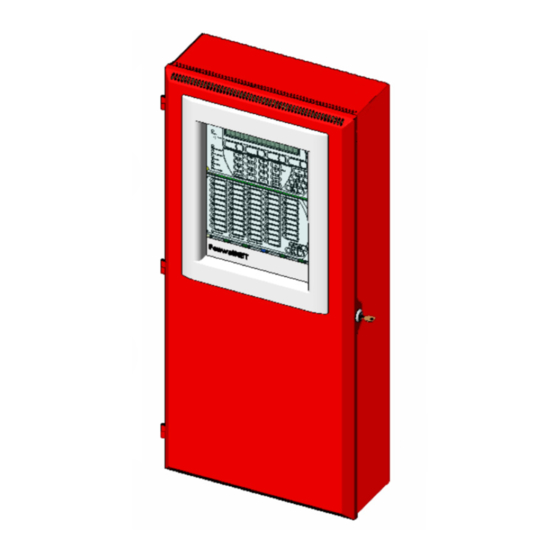
Kidde Fire Systems ARIES NETLink Installation, Operation And Maintenance Manual (294 pages)
Intelligent Fire Alarm-Suppression
Brand:
Kidde Fire Systems
| Category:
Control Unit
| Size: 11.91 MB
Table of Contents
Terms and Abbreviations
4
Safety Summary
5
Table of Contents
9
Table of Contents
10
List of Figures
15
Chapter 1 General Information
21
Introduction
21
Listings and Approvals
21
Codes and Standards
21
Suppression System Standards
22
Other Standards
22
System Description
23
System Components
24
Optional Components
24
System Enclosure Types
24
1-7.1 Enclosure Features
25
Keypad and Display
29
Keypad/Display Features
29
Main Controller Board (MCB)
30
Main Controller Board Features
31
Power Supply/Pmu Assembly
31
1-10.1 Power Supply Units
32
1-10.2 Power Management Unit (PMU) Board
32
Batteries
33
Expansion Card Cage
34
1-12.1 Expansion Backplane
34
Optional Expansion Cards
36
General Guidelines for the Use of Expansion Cards
36
Expansion Card Slot Addresses
36
Optional Remote Devices
41
1-14.1 Remote Devices Using RS232 or USB Ports
41
1-14.2 Remote Devices Using RS485 Bus to MCB
42
Signaling Line Circuit (SLC) Devices and Modules
45
1-15.1 Smartone® Devices
45
High Sensitivity Smoke Detectors
46
Smartone Addressable Modules
47
Optional Software
50
Remote Configuration Software
50
System Specifications
51
Chapter 2 Installation
57
Introduction
57
Preparing for Installation
57
Unpacking the System
57
2-2.2 Materials/Tools Required
58
2-2.3 Determining Wall Location
58
2-2.4 Removing Knockouts from Enclosure
58
Installing Conduit
59
Installing Electrical Boxes
59
Overview of Installation Steps
59
Step One: Shut off AC Power
59
Step Two: Prepare the Enclosure and Electrical Wiring
59
Step Three: Mount the Enclosure
59
Step Four: Install the Top Tier Power Supply/Pmu Assembly and MCB
59
Step Five: Install Expansion Card Cage and Included Cards (if Applicable)
59
2-3.6 Step Six: Install Batteries
60
2-3.7 Step Seven: Install Expansion Enclosures And/Or Remote Modules (if Applicable)
60
2-3.8 Step Eight: Auto-Configuring the System
60
2-3.9 Step Nine: Uploading the Configuration File and Performing the Pre-Test
60
2-3.10 Step Ten: Performing Final System Test and Commissioning the System
60
2-3.11 Step Eleven: Installing the Actuation Devices and Extinguishing System
60
2-3.12 Step Twelve: Performing Final Installation Procedures
60
Standard System Installation Procedure
61
2-4.1 Surface Mounting of Main or Expansion Enclosures
61
2-4.2 Semi-Flush Mounting of Main or Expansion Enclosures
62
Installing a Power Supply Unit into the Enclosure Top Tier
64
2-4.4 Installing the Power Management Unit (PMU) Board into Enclosure Top Tier
65
Connecting the Audible PMU Trouble Sounder Harness
69
Making AC Power Source and Earth Ground Connections
69
2-4.7 Installing the Main Controller Board into Enclosure Top Tier
72
Replacing Enclosure Door
74
Making Internal 24Vdc Power Connections
75
Making Internal Communication Connections
76
Optional Equipment Installation Procedure
77
Installing the Expansion Card Cage
77
2-7.2 Inserting and Securing an Expansion Card
79
2-7.3 Installing Add-On Power Supply/Pmu Assembly with Bracket
80
2-7.4 Installing the Battery Tray
81
Connecting Standby Batteries to PMU Board
82
Setting up Wiring to Field Devices
83
Installing Electrical Wiring and Making Connections
83
Overview of SLC Wiring Styles
83
Electrical Supervision
83
2-8.4 Wiring Auxiliary Power Outputs
84
2-8.5 Wiring Signaling Line Circuits
84
2-8.6 Wiring Notification Appliance Circuits
90
2-8.7 Wiring R-NAC (Combination) Circuits
92
2-8.8 Relay Outputs
95
2-8.9 City Tie Wiring
96
Digital Alarm Communicator Transmitter (DACT) Wiring
97
Internet Communications Module (ICM) Wiring
98
Setting up RS232 / USB Communications
99
2-11.1 Setting up RS232 Communications Port
99
2-11.2 Setting up USB Communications Ports
100
2-11.3 Connecting a Laptop, Remote Computer or Printer
100
Setting up Remote RS485 Peripheral Devices and Enclosures
101
2-12.1 Installing the Remote Enclosure
102
2-12.2 Installing the ATM-L Annunciator Driver Module
106
2-12.3 Installing the ATM-R Relay Driver Module
106
Setting up Network Equipment
106
2-13.1 Network Interface Card (NIC)
106
Installing the Fiber Optic Converter Module (FOCM)
108
2-14.1 Fiber Optic Converter Module (FOCM) Wiring - Single Channel
109
2-14.2 Fiber Optic Converter Module (FOCM) Wiring - Dual Channel
110
Installing the Large Capacity Battery Cabinet
111
Chapter 3 Configuration and Programming
113
Introduction
113
Initial Signaling-Line Circuit Configuration
113
3-1.2 Site-Specific Programming
115
Menu Operation
116
Overview of Main Menu Functions
116
ISOLATE Menu Functions
118
3-3.2 LIST Menu Functions
124
3-3.3 SET Menu Functions
130
3-3.4 TEST Menu Functions
157
Chapter 4 Operation
167
Introduction
167
Operating States
167
4-2.1 the Event Output Control (EOC) Program
168
User Interface Keys and Functions
168
Operator Control Keys
169
4-4.1 User Interface Button Operations
170
Alphanumeric Keypad
171
Status-Indicating Leds
172
LCD Panel System Status Messages
173
Using Passwords for System Security
173
4-8.1 Levels of Security
173
4-8.2 Default Passwords
174
4-8.3 Entering Passwords
174
System Startup Procedure
174
4-9.1 Preliminary Procedures
174
Initial Power-Up
175
ARIES Netlink System Operation Overview
178
4-10.1 Normal Operation
178
4-10.2 Trouble State
178
Alarm State
180
Supervisory State
185
4-10.5 Pre-Alarm State
186
4-10.6 Concurrent States
188
Chapter 5 Networking
195
Network System Operation
195
Communications
197
Network Event Broadcasts
197
Operator Control
197
Event Output Control (EOC)
198
5-8.1 Accessing Remote Nodes Via Keypad
198
5-8.2 Network Groups
198
5-8.3 Operating States
204
Operator Control Keys
205
Status-Indicating Leds
205
Network Display Messages
205
Remote Trouble Events
205
5-8.8 Remote Alarm Events
206
Remote Positive-Alarm-Sequence (PAS) Events
207
Remote Alarm-Verification Events
207
5-8.11 Remote Supervisory Events
208
5-8.12 Remote Pre-Alarm Events
209
How Concurrent Remote Events will be Displayed
210
Network Start-Up
213
Chapter 6 Testing and Maintenance
219
Introduction
219
Semi-Annual and Annual Testing
219
Lamp Test
219
Battery Test
219
6-2.3 Initiating-Devices Test
220
6-2.4 Walk Test
220
MCB Clock Battery Replacement
220
Testing Frequency
221
Fuse Replacement
221
Chapter 7 Troubleshooting
223
Introduction
223
Chapter 8 Parts List
251
Available Parts
251
Appendix Abattery and Power Supply Calculations
255
APPENDIX B- Wiring Requirements for ARIES Netlink Signaling Line Circuit
263
Appendix Clist of Agency Listed Compatible Devices
265
Appendix Dfm Rules for Preaction/Deluge Systems
269
Appendix Eroutings for Power-Limited and Non-Power- Limited Wiring
271
Appendix Faries Netlink for Canadian Applications
279
Canadian Application-Style Enclosures
279
Installation
280
F-2 Installation
280
Appendix Garies Netlink for City of Chicago Applications
281
Introduction
281
G-1 Introduction
281
Overview of the Stand-Alone Control Box
282
G-2.1 Fire Alarm Trouble
282
G-2.2 City Tie Trouble
282
City Disconnect Switch
282
Installation and Connections
283
Labeling
283
G-2.3 City Disconnect Switch
283
Field Wiring Connections
285
APPENDIX H- Conversion Instructions for Pegasys
287
Introduction
287
H-1 Introduction
287
Optional Parts (Not Included in Retrofit Kit
289
Parts for the Control Unit Bottom Tier
289
Additional ARIES Netlink Parts
289
Tools Required
290
Preparation
290
Procedure
290
Advertisement
Advertisement
Related Products
Kidde Fire Systems Argonite
Kidde Fire Systems PEGAsys LV
Kidde Fire Systems Categories
Control Unit
Fire Extinguisher
Motherboard
Fire Alarms
Firefighting Equipment
More Kidde Fire Systems Manuals
Login
Sign In
OR
Sign in with Facebook
Sign in with Google
Upload manual
Upload from disk
Upload from URL