Advertisement
Quick Links
ARIES
-MLX, ARIES
®
LED and Relay Output Driver Modules
Models ATM-L and ATM-R
FEATURES
•
Model ATM-L supports 32 programmable, supervised
LED outputs, 6 system-level LED outputs and 5 system-
level input circuits
•
Model ATM-L supports 32 programmable LED outputs, 6
system LED outputs and 5 system inputs
•
Model ATM-R activates up to 32 programmable relays
DESCRIPTION
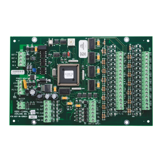
The Model ATM-L Annunciator (LED) Driver Module (P/N
76-200004-032) provides ARIES
legacy control units (ARIES
to 32 programmable, supervised LED outputs for graphi-
cal or tabular annunciators, along with 6 system-level
LED outputs and 5 system-level input circuits for func-
tional switches.
The system-level LEDs correspond to the following gen-
eral conditions:
•
Module Power
•
Alarm
•
Pre-Alarm
•
Alarm Silence
•
Supervisory
•
Trouble
The functional switches provide for the following operator
intervention:
•
System Reset
•
Event Acknowledgment
•
Alarm Silence
•
Fire Drill
•
Lamp Test
The Model ATM-R Relay Driver Module, P/N 76-200005-
032, can activate up to 32 programmable, supervised
relays.
These modules communicate with the control unit via an
external RS-485 communications circuit, with the most-
remote module capable of being located up to 4,000 feet
from the control unit. Up to 16 remote ATM-L, ATM-R or
combination of both can be mixed with up to 15 RDCMs
on the control unit's RS-485 circuit.
Both modules can be powered from the control unit's
power supply, or from an external, regulated, and power-
limited power supply Listed for use with fire-protective-
signaling equipment.
-SLX
®
®
-MLX, ARIES
®
-SLX or
®
NETLink, ARIES
®
) with up
•
Up to 16 ATM-L, ATM-R or combination of both per
control unit
•
Can be mixed with up to 15 RDCMs per control unit
•
Can be installed up to 4000 feet (1219 meters) from
control unit
•
Supports applications with legacy Kidde Fire Sys-
tems control units
•
UL Listed and FM Approved
Model ATM-L Annunciator Driver Module
INSTALLATION
The ATM-L Module is intended for mounting inside the
enclosure of a UL-864 Listed remote annunciator. Use
the mounting hardware provided with the module. Wire
routing and installation methods are to be in accordance
with the annunciator installation instructions.
The ATM-R is intended for mounting inside the enclosure
of a UL-864 Listed accessories cabinet. Use the mount-
ing hardware provided with the module (see Figure 1).
ATM-L/R
Out B
Out A
In B
In A
W1
4.625
+24 V
Com
5.000
PS Flt
Earth Gnd
A
B
0.188
1.375
Note:
Maintain a minumum one-half (1/2) inch clearance around ATM-L
and ATM-R Modules when installed in mounting enclosure.
Figure 1. Module Mounting Dimensions
Effective: May 2020
K-76-236
S2
S1
LK17
LK32
LK16
LK15
16
32
15
LK31
LK30
31
30
14
LK14
LK13
13
29
LK29
LK28
12
28
LK12
LK11
11
27
10
LK27
LK26
26
25
9
LK10
LK9
8
24
LK25
LK24
7
23
LK8
LK7
6
22
LK23
LK22
21
5
4
20
LK6
LK5
3
19
Trouble
Lamp Test
LK21
LK20
2
18
Sup.
Com
LK4
LK3
1
17
Sil. Out
Ack
LK19
LK18
Pre Alm
Reset
Alarm
Silence
LK2
LK1
Pwr On
Drill
5.175
8.000
Advertisement

Subscribe to Our Youtube Channel
Summary of Contents for Kidde Fire Systems ARIES-MLX
- Page 1 ARIES -MLX, ARIES -SLX ® ® LED and Relay Output Driver Modules Models ATM-L and ATM-R Effective: May 2020 K-76-236 FEATURES • Model ATM-L supports 32 programmable, supervised • Up to 16 ATM-L, ATM-R or combination of both per LED outputs, 6 system-level LED outputs and 5 system- control unit level input circuits •...
- Page 2 KIDDE-FENWAL, INC. assumes no responsibility for the product's suitability for a particular application. The fire suppression system design, installation, maintenance, service and troubleshooting must be performed by trained, authorized Kidde Fire Systems distributors for the product to work correctly.


Need help?
Do you have a question about the ARIES-MLX and is the answer not in the manual?
Questions and answers