
Related Manuals for Lenord+Bauer GEL 235 Series

Summary of Contents for Lenord+Bauer GEL 235 Series
- Page 1 Absolute Rotary Encoders GEL 235/235x/203x Single/Multiturn, SSI/Analog/Fieldbus Interface Mounting Instructions Right to technical changes and errors reserved. 2012-07...
- Page 2 Device manufacturer and publisher: Lenord, Bauer & Co. GmbH Dohlenstraße 32 Doc. no. D-02M-Abs2x (1.2) 46145 Oberhausen ● Deutschland Phone: +49 208 9963–0 ● Fax: +49 208 676292 Internet: www.lenord.de ● E-Mail: info@lenord.de GEL 235/235x/203x...
-
Page 3: Table Of Contents
Lenord+Bauer Table of contents Table of contents About this manual .................... 5 General information ................. 5 Validity ..................... 5 Other applicable documents ..............5 Target group .................... 6 Abbreviations and explanations of terms ..........6 Symbols, signal words, notes ..............6 Safety instructions ................... - Page 4 Table of contents Lenord + Bauer Disposal ....................26 Maintenance ....................27 Malfunctions ....................28 Technical data ....................29 Specifications ..................29 Dimensional drawings ................29 9.2.1 GEL 235 ..................29 9.2.2 GEL 2351/2352 ................. 31 9.2.3 GEL 203x .................. 33 Mounting accessories ................
-
Page 5: About This Manual
Lenord+Bauer 1 About this manual General information About this manual The absolute rotary encoders dealt with comprise the following devices: Global features/pptions Name Type SSI Analog U Analog I Resolver Fieldbus Ex protection GEL 235 S, M1 C, E, P... -
Page 6: Target Group
1 About this manual Lenord + Bauer Target group ● Operating instructions for GEL 235 Ex design Target group These Mounting Instructions are intended for operators, manufacturers, electrical en- gineers, and licensed electricians under the supervision of an electrical engineer. Abbreviations and explanations of terms Direct current Electrostatic discharge, or Electrostatic sensitive device... -
Page 7: Safety Instructions
Lenord+Bauer 2 Safety instructions Designated use Safety instructions Designated use The absolute rotary encoders are intended exclusively for measurement tasks in the industrial and commercial realm. It is to be installed in a system and requires the con- nection to special evaluation electronics, which, for example, are contained in a posi- tioning controller or an electronic counter. -
Page 8: Notes About Avoiding Property Damage And Malfunctions
2 Safety instructions Lenord + Bauer Avoiding property damage Notes about avoiding property damage and malfunctions The encoders are designed to be extremely robust. Nevertheless, they can be damaged due to impermissible mechanical loads. Mechanical damage can quickly cause the failure of the measurement system. -
Page 9: Saving Battery Power (Gel 2035 Multiturn Only)
Lenord+Bauer 2 Safety instructions EMC notes 2.5.5 Saving battery power (GEL 2035 multiturn only) The encoder can be put in a “sleep mode” to lengthen battery’s life (delivery condition). This is applicable for the following situations: ● Longer lasting abandonment of the plant ●... - Page 10 2 Safety instructions Lenord + Bauer EMC notes The sensor is part of a machine or system. Incorporate the potential equalization for the sensor into the overall screening concept. Lay signal and control lines spatially separated from the power cables. If this is not possible, then use pair-stranded and screened cables and/or lay the encoder cable in a steel conduit.
-
Page 11: Description
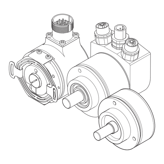
Lenord+Bauer 3 Description Task Description Task The absolute rotary encoder measures the angle of a machine axis via one or several turns and delivers a corresponding digital output signal. Construction Exemplary illustration for GEL 235 with axial cable outlet (on the left) and radial con-... -
Page 12: Ssi Data Output
3 Description Lenord + Bauer SSI data output With the SSI variant, the position value is output serially in binary or grey code. Fur- thermore, this encoder delivers 64 sin/cos differential signals per revolution for an ex- ternal interpolation. With the analog variant, the absolute position is output either as 0–10 V voltage or 4– 20 mA current values. -
Page 13: Mounting
Lenord+Bauer 4 Mounting Check fixture Mounting The following steps are required for the mounting of the encoder: 1. Check fixture 2. Mount encoder 3. Mount fieldbus cable with corresponding encoder type 4. Lay cable Check fixture For all required measurement details, see the dimensional drawings in section (→... -
Page 14: Synchro Flange
4 Mounting Lenord + Bauer Mount encoder Since the encoders can be used many different ways, the way it is attached is also variable. Therefore, no step-by-step instructions for installation will be provided here, but rather only a graphic overview of some usual mounting possibilities (mainly for GEL 235). - Page 15 Lenord+Bauer 4 Mounting Mount encoder ● Attachment on a mounting bracket (accessory part from LENORD+BAUER) ● Mounting using a clamping device GEL 235/235x/203x...
-
Page 16: Semi Hollow Shaft
4 Mounting Lenord + Bauer Mount encoder 4.2.3 Semi hollow shaft If not factory-adjusted: Attach the torque supply to the encoder using four cross-head screws (1); tightness: 1 Nm. Push the clamping ring loosely onto the semi hollow shaft (2). ... -
Page 17: Flex Flange (Gel 2037)
Lenord+Bauer 4 Mounting Mount encoder 4.2.4 Flex flange (GEL 2037) Push the Flex flange onto the clamping flange of the encoder (1). Turn the encoder slightly until its three M4 threaded holes fit the corresponding bore holes in the Flex flange (2). -
Page 18: Cable Mounting With Gel 235 Interface Cover
4 Mounting Lenord + Bauer Cable mounting with GEL 235 interface cover Cable mounting with GEL 235 interface cover Disconnect the interface cover and encoder: Remove 2 screws on the back side of the interface cover. Prepare the cable gland, bus cable, and supply cable (only PROFIBUS) as follows and mount: 55 mm 8 mm... -
Page 19: Lay Cable
Lenord+Bauer 4 Mounting Lay cable Lay cable Lay the cable paying attention to the EMC notes (→ page Seal unused connector sockets by a cap or dummy/bus termination connector to keep the specified protection class. GEL 235/235x/203x... -
Page 20: Commissioning
5 Commissioning Lenord + Bauer Connection Commissioning Check whether all cables are laid and the encoder is mounted firmly. Connection Connection of the fieldbus variants: → separate Reference document. Check whether the connector plug is wired correctly, according to the connection schemes further below. - Page 21 Lenord+Bauer 5 Commissioning Connection 12-pole connector M23 (GEL 235, GEL 203x) Cable Signal Explanation blue Ground brown DATA+ Output: Differential data signal according to RS 485 grey- CLOCK+ Input: Differential data signal according to RS 485 pink yellow SIN– green...
- Page 22 5 Commissioning Lenord + Bauer Connection 17-pole connector with resolver M23 (GEL 203x) Resolver Explanation signals signals see schematic further below not connected CLOCK– Input: Differential data signal according to RS 485 DATA– Output: Differential data signal according to RS 485 Ground Supply voltage PRESET...
-
Page 23: Analog
Lenord+Bauer 5 Commissioning Function check 5.1.2 Analog 8-pole connector M12 (GEL 235, GEL 2351) Signal Explanation Ground PRESET Istwert auf Messbereichsmitte setzen T_Low Teach-in: low limit of measuring range T_High Teach-in: high limit of measuring range AOUT Analog output 4–20 mA/0–10 V... -
Page 24: Measured Value Adaptation
5 Commissioning Lenord + Bauer Measured value adaptation Measured value adaptation Prerequisite for the adjustments described in the following: ● The encoder is supplied with voltage. ● The machine axis with coupled encoder can be turned manually (mechanically or electrically). 5.3.1 PRESET (SSI, analog) By means of the PRESET function the actual position is set to the centre of the meas-... -
Page 25: Counting Direction (Ssi, Analog)
Lenord+Bauer 5 Commissioning Measured value adaptation Principle (example for current output): T_Low T_High 20 mA 4 mA Position 0° 65° 210° 360° , Out Output signal graph before (index 0) or after (index T) the adaptation via the teach-in signals; the desired working range is shaded in grey, the degree specification on the x-axis is selected arbitrarily Output signal 4–20 mA... -
Page 26: Disassembly And Disposal
6 Disassembly and disposal Lenord + Bauer Disassembly Disassembly and disposal Disassembly of the encoder If a still-intact device should be removed, for example for a retrofitting, only touch the plug pins and connection wires with suitable body grounding, for example using an ESD armband in order to prevent damage to the electronic components due to electrostatic discharge. -
Page 27: Maintenance
The encoder contains no parts that require maintenance. Do not try to repair the encoder yourself. Necessary repairs may only be made by LENORD+BAUER or an explicitly-authorized agent. No change may be made to devices that are operated in areas subject to explosion. -
Page 28: Malfunctions
8 Malfunctions Lenord + Bauer Malfunctions Additional malfunctions in the fieldbus variants are listed in the separate Reference manual of the respective type. Malfunction Possible causes Remedy No or low output Electrical connection Check all electrical connections signal defective between the encoder and the power supply as well as the eval- uation electronics to ensure that they are correct, contact is se-... -
Page 29: Technical Data
The specifications for the particular encoder can be found in the Product Information supplied with the encoder and in the Technical Information data sheet that can be downloaded from the LENORD+BAUER website (→ www.lenord.de). For the GEL 235 Ex design, different or complementary details apply in some cases (→... - Page 30 9 Technical data Lenord + Bauer Dimensional drawings Semi hollow shaft 1 Nm ( 2) Connection variants (P = PRESET-button) 22.4 Axial connector socket Radial connector socket SW17 Axial cable gland axialflex® cable outlet GEL 235/235x/203x...
-
Page 31: Gel 2351/2352
Lenord+Bauer 9 Technical data Dimensional drawings 15.6 20.5 Interface cover (example for PROFIBUS-DP) 9.2.2 GEL 2351/2352 Synchro flange Clamping flange GEL 235/235x/203x... - Page 32 9 Technical data Lenord + Bauer Dimensional drawings Semi hollow shaft (only GEL 2352 and GEL 2035) 49.3 1 Nm ( 2) 37.8 Single turn 50.8 1 Nm ( 2) 42.3 53.8 Multiturn GEL 235/235x/203x...
-
Page 33: Gel 203X
Lenord+Bauer 9 Technical data Dimensional drawings 9.2.3 GEL 203x Clamping flange 13.6 3x M4 / 7 tief deep Measure A (mm): GEL 2035 GEL 2037 44.9 SSI + Resolver 63.1 52.8 Heavy duty flange 69.7 Clamping flange with target wheel adaptor 29.9... -
Page 34: Mounting Accessories
Type IP 69K (only GEL 2035) 3x M 4 / 7 tief deep 37.2 Mounting accessories For the encoder mounting, LENORD+BAUER offers the following accessories, among others (dimensions in mm): Clamping elements KL200 (3 pcs) Metal coupling MK12 Ø 9 M 4 , 9 0 °... - Page 35 Lenord+Bauer 9 Technical data Mounting accessories Plastic bushing RH23501–3 Mounting bracket MW52 28.5 Type RH 23501 8 mm RH 23502 10 mm RH 23503 12 mm Adaptor flange MF23501 Adaptor flange MF23502 Soft torque support FB23505 Hard torque support FB23504 Flex flange FB23507 / FB23508 (nur GEL 203x) F: Spring deflection 3 mm, max.
-
Page 36: Manufacturer's Declaration
9 Technical data Lenord + Bauer Manufacturer's declaration Manufacturer's declaration You can find the manufacturer's declaration according to EMC Directive 2004/108/EU on our website www.lenord.de. GEL 235/235x/203x...
Need help?
Do you have a question about the GEL 235 Series and is the answer not in the manual?
Questions and answers