Advertisement
Quick Links
Advertisement

Related Manuals for Sportop B700


Summary of Contents for Sportop B700
- Page 1 B700 ENGLISH...
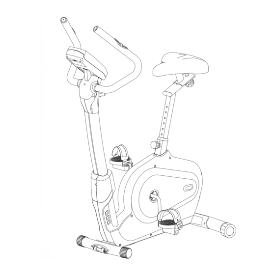
- Page 2 FRONT STABILIZER REAR STABILIZER CENTRAL TUBE SADDLE TUBE MAIN FRAME MOVEING BASEMENT COMPUTER HOLDER HANDLE BAR J1 PEDAL (L) J2 PEDAL (R) COMPUTER PEDAL REAR DECORATION SADDLE DECORATION COVER Tools...
- Page 3 FIGURE_1 ASSEMBLY FOR FRONT STABILIZER Fix the front stabilizer (B) with the main frame(A) by bolts(P2), washers(P3) & nuts(P4). USE TOOL FIGURE__2 ASSEMBLY FOR REAR STABILIZER Fix the rear stabilizer(C) with the main frame (A) by bolts(P1), washers(P3) &...
- Page 4 FIGURE_3 ASSEMBLY FOR CENTRAL SUPPORT TUBE STEP 1.Take off the bolt (A3), washer (A4) from the central tube (D) before assembly. STEP 2. Equip the cable of tension control (D1) in the slot of tension cable iron brackte (A1) as shown in ViewA-1. Fit togetehr the large and small brass barrels and tighten by turning with your fingers as shown in ViewA-2.
-
Page 5: Adjust The Saddle
FIGURE_4 ASSEMBLY SADDLE SUPPORT TUBE & SADDLE WITH MAIN FRAME STEP 1. Loosen the knob(A5) and keep on pulling it. Then, insert the saddle support tube(E) into the main frame(A).Release the knob(A5) after the saddle support tube is equipped appropriately. Please make sure the knob has been equipped exactly into the adjusting hole of the saddle support tube(E). - Page 6 FIGURE_6 ASSEMBLY THE COMPUTER & FRONT DECORATION COVER STEP 1: Connected the sensor wire and computer wire and position the computer (G) into the computer holder (N). STEP 2: Take off the screws (D3) from the central tube (D) and position the front decoration cover (M) on the central tube tightly by screw (D3).
- Page 7 FIGURE_7 ASSEMBLY PEDAL WITH MAIN FRAME Step 1.Equip the left pedal(J1) with the cra nk by anti-clockwise direction. Step 2.Equip the right pedal(J2) with the cra nk by clockwise direction. USE TOOL FIGURE_8 HOW TO MOVE MACHINE Step1.
- Page 8 F2-3 F1-2 F1-1 F1-3 F2-2 F2-4 F2-1 F1-4 A35 A34 A24-4 A24-3 A24-2 - 7 - A24-1...
- Page 9 DESCRIPTION Q'TY DESCRIPTION Q'TY END CAP END CAP HOLDER OF WHEEL SCREW REAR STABILIZER END CAP CENTRAL TUBE DRIVING PULLY TENSION SENSOR WIRE SCREW DECORATION COVER DECORATION COVER SCREW SCREW TENSION COVER SEAT POST SPRING MOVING BASEMENT END CAP HANDLE BAR A24-1 PULSE SENSOR SCREW...
- Page 10 PEDAL(L) NUT M8 PEDAL(R) WASHER M8.5X19 FRONT DECORATION COVER SCREW M8X45L REAR DECORATION COVER SPRING WASHER M8 WASHER M8.5X19 COMPUTER HOLDER REAR DRCORATION COVER - 9 -...
- Page 11 FUNCTION : 0~15~999 SPEED : 0.0~99.9 KM/ML TIME : 0:00~99:00. Count up and down are available. DISTANCE : 0.00~99.50 K/M,Count up and down are available. CALORIES : 0~9990,Count up and down are available. PULSE : P~30~240,maximum value is settable. USER DATA : U1 ~U9 ( U1 ~ U9 memorized user data AGENDA / SEX : GIRL / BOY SYMBOL select : 10-25-99...
- Page 12 5. BODY FAT : Press the “BODY FAT” key, and hold hand-pulse with both hand 6 seconds. The LCD monitor show the user 1-user 4‘s body fat percent. AREA GENDER THIN STAND EXTRA FAT MALE <10% 10%~19.9% 20%~24.9% ≧ ASIA FEMALE <20% 20%~29.9%...
Need help?
Do you have a question about the B700 and is the answer not in the manual?
Questions and answers