
Subscribe to Our Youtube Channel
Related Manuals for Frigomat Taylor C119 06 Series


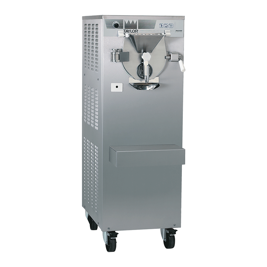
Summary of Contents for Frigomat Taylor C119 06 Series
- Page 1 MANTECATORI ORIZZONTALI ELETTRONICI ELECTRONIC HORIZONTAL BATCH FREEZER MANUALE D’USO MANUTENZIONE OPERATING INSTRUCTION AND MAINTENANCE Serie-Series-Série-Serie C119 06 C122 03...
- Page 2 IMPORTANT We recommend that you read this manual fully and carefully before using your appliance. It is in your interest to pay special attention to the warnings marked as follows: Failure to comply with this signal causes very serious risks for health, death, and medium and long term permanent damage.
- Page 3 The machine is covered by warranty according to the terms illustrated in the "WARRANTY CARD" supplied. It must be properly filled in and returned to: FRIGOMAT s.r.l., via 1° Maggio, 28 26862 GUARDAMIGLIO (LODI) – ITALY Please write the serial number of your machine in the field below.
-
Page 4: Table Of Contents
INDEX 1. TRANSPORTATION, HANDLING AND STORAGE……… …………………………………… Preliminary inspection Dimensions and weights of packaged machines…………… ……………… Indications for decommissioning ………………………………………… 2. MARKING AND GRAPHIC SIGNS 3. GENERAL SAFETY STANDARDS …………………………………… ………………………………………… 4. INSTALLATION ………………………………………… 4.1 Use ………………………………………… 4.2 Working limits …………………………………………... -
Page 5: Transportation, Handling And Storage
1 TRANSPORTATION, HANDLING AND STORAGE. 1.1 PRELIMINARY INSPECTION AND STORAGE The machine is transported at the risk and peril of the customer. If you notice any damage to the packaging, immediately inform the carrier. Inform the carrier right after opening the package if the machine is damaged even if it is a few days after delivery. -
Page 6: Marking And Graphic Signs
2. MARKING AND GRAPHIC SIGNS The machine is provided with an identification plate and some pictograms. They must be known along with the manual to guarantee safe use. Machine data plate The adhesive plate applied on the rear enables to identify the model. - Page 7 Attention! High voltage inside; danger of electrocution. This plate is applied on the cover of the electrical box and warns the operator that it must not be removed for any reason whatsoever, thus avoiding the danger of electrocution which could be fatal. In this case as well, maintenance of internal components is reserved for qualified personnel.
-
Page 8: General Safety Standards
3. GENERAL SAFETY STANDARDS Strictly observe the general safety and accident-prevention standards listed hereafter: Use of the machine is NOT suitable for persons (including children) having reduced physical, sensorial or mental abilities, or lacking in experience and knowledge, unless supervised or trained on using the machine by a personal responsible for their safety. -
Page 9: Installation
4. INSTALLATION 4.1 USE Appliance suitable for batch freezing of ice cream mixtures and slush production, according to use allowed by Law. 4.2 WORKING LIMITS Do not use the machine with inconstant power supplies or +/- 10% beyond the value indicated on the plate or with the power cable damaged;... -
Page 10: Activation
4.5 ACTIVATION TAYLOR declines all and any liability for damage caused by failure to comply with the following indications. This lack of compliance causes the warranty to terminate. Connection of the machine to the water mains must be performed respecting national regulations of the Country where the machine is installed. - Page 11 If needed, carry out an equipotential bonding, using the screw placed on the rear of the machine below the frame and marked with the symbol shown to the left. Make sure that the cold water supply line intended for condensation has pressure values between 1 and 3 BAR and temperature between 13°...
- Page 12 2. Condensation pressure (water models only). With the machine in production mode, after a few seconds condensation water must come out of the drain pipe at a temperature of about 35°C. If this is not the case, the pressure switch valve shown in the figure must be adjusted.
-
Page 13: Safety Devices
5. SAFETY DEVICES Shearing-prevention safety device: Implemented by means of a safety circuit compliant with the European directive, it intervenes when the door is opened and/or when the safety grid on the hopper is lifted, temporarily switching the machine to STOP mode. Beater motor overheating safety device: Implemented by means of a thermal relay;... -
Page 14: Operation
6. OPERATION 6.1 MACHINE 1. Door Closes the cylinder hermetically during the processing phases. It can be easily removed for cleaning. 2. Safety grid – hopper cover Allows the operator to load the product safely. The cover keeps the mixture from coming into contact with dust. -
Page 15: Controls
6.2 CONTROLS DISPLAY Displays the information relative to work programs and allowed adjustments. The LED switches on to signal when the door is opened, when the safety grid is lifted or any anomalies of the system. STOP In whatever operating phase the machine is in, pressing the STOP key stops the machine and cancels the function in progress. - Page 16 3. SEMI-AUTOMATIC CYCLE with consistency control. With the machine in automatic Hard cycle, by pressing the PRODUCTION key again it is possible to access the semi- automatic cycle with consistency control that enables the operator to manually select the level of consistency one wishes to achieve. 4.
-
Page 17: Slush And Ice Cream Production
6.3 ICE CREAM AND SLUSH PRODUCTION After having installed the machine in compliance with the instructions of chapter 3 and having accurately washed and sanitised it, according to the instructions contained in chapter 7, proceed as follows to start ice cream making: - Make sure that the gate valve of cold water for condensation is open (water models only). -
Page 18: Automatic Cycle
6.3.1 AUTOMATIC CYCLE - Press the PRODUCTION key to start the automatic batch freezing cycle. (Fig. 1) - The AUT message is viewed on the display for a few seconds to confirm the automatic cycle has been selected (Fig. 2); subsequently, during batch freezing, the instantaneous consistency numerical value is displayed.(Fig. -
Page 19: Automatic Hard Cycle
6.3.2 AUTOMATIC HARD CYCLE - Press the PRODUCTION key to start the automatic batch freezing cycle, as described in the previous section. - The AUT message is viewed on the display for a few seconds to confirm the automatic cycle has been selected - To activate the automatic Hard cycle, press the Fig.1... -
Page 20: Semi-Automatic Cycle With Consistency Control
6.3.3 SEMI-AUTOMATIC CYCLE WITH CONSISTENCY CONTROL (only for experts) - Press the PRODUCTION key, as described in the previous sections. - The AUT or HRD message is viewed on the display for a few seconds to confirm the automatic or automatic HARD cycle has been selected. - Page 21 In order to correct any initial programming errors, during the execution of the semi-automatic cycle it is Fig.1 always possible to vary the consistency setting via the following procedure: - With cycle progress, press Fig.2 PRODUCTION key once. - The LEDs of the UP, Confirm and DOWN keys light up and the SAC message relative to the cycle in progress is viewed on the display.
-
Page 22: Semi-Automatic Cycle With Time Control
6.3.4 SEMI-AUTOMATIC CYCLE WITH TIME CONTROL (only for experts) - Press the SEMI-AUTOMATIC TIME CYCLE key to select the semi-automatic batch freezing cycle with time control (fig. 1). - The LEDs of the UP, Confirm and DOWN keys light up and the time setting, expressed in minutes and between 0’... - Page 23 In order to correct any initial programming errors, during the execution of the semi-automatic cycle it is always possible to vary the time setting via the following procedure: With the cycle in progress, press the SEMI- Fig.1 AUTOMATIC TIME CYCLE key (fig. 1). - The LEDs of the UP, Confirm and DOWN keys light up and the time value is viewed on the display: press the UP and DOWN keys to correct...
-
Page 24: Slush Program
6.3.5 SLUSH PROGRAM WITH CONSISTENCY CONTROL - Press the SLUSH key (fig.1). - The LEDs of the UP, Confirm and DOWN keys light up and the GR1 message is viewed on the display, which distinguishes the slush production program with consistency control and continuous mixing (fig. - Page 25 In order to correct any initial programming errors, during the execution of the GR1 cycle it is always possible to vary the consistency setting via the following procedure: Fig.1 With the cycle in progress, press the SLUSH key (Fig.1) once. - The LEDs of the UP, Confirm and DOWN keys light up and the GR1 message relative to the cycle in progress is viewed on the display (fig.
-
Page 26: Coffee Slush Program
6.3.6 COFFEE SLUSH PROGRAM - Press the SLUSH key (fig.1). - The LEDs of the UP, Confirm and DOWN keys light up and the GR1 message (fig. 2) is viewed on the display. - Press the UP key to view the GR2 message on the display that distinguishes the slush production Fig.1 program with processing time control and cyclic... - Page 27 In order to correct any initial programming errors, during the execution of the GR2 cycle it is always possible to vary the time setting via the following Fig.1 procedure: With the cycle in progress, press the SLUSH key once. (fig. 1) - The LEDs of the UP, Confirm and DOWN keys light up and the GR2 message relative to the cycle in progress is viewed on the display.
-
Page 28: Extraction
6.4 EXTRACTION To extract the product at the end of a productive cycle, refer to the following instructions: - Position cold and clean tub of adequate capacity on the front shelf of the machine. - Check that the production cycle has ended. - C119 model : rotate the steel lever connected to the dispenser disk anti-clockwise to the right. -
Page 29: Maintenance
7. MAINTENANCE 7.1 ROUTINE MAINTENANCE (INTENDED FOR USER) The fats present in the ice cream mixtures are ideal fields for the proliferation of bacterial loads and mould. To eliminate this serious problem, all the parts which come into contact with the product must be thoroughly washed and sanitised by careful procedures and using suitable sanitising products. - Page 30 Pour the maximum admitted load of cold drinking water into the machine to rinse the surfaces which were just treated with the sanitiser. Drain the rinse water and turn the machine off. When pre-washing is over, all the removable parts in contact with the product must be disassembled and sanitised in a separate tub.
- Page 31 9. Remove the steel lever that controls the dispenser disk from the central door pin. 10. Remove the spring. 11. Remove the dispenser disk. 12. Use the OR disassembly device to remove the 2 OR gaskets from their place. Immerse the previously disassembled components into the tub with the sanitising solution and brush the surfaces with care.
- Page 32 REMOVING AND CLEANING STIRRER Pull the beater towards you to remove it from the batch freezing cylinder. Recover the seal gasket placed on the back of the beater. Remove the scrapers from the beater by pressing firmly on the small fixing tooth. ...
- Page 33 RINSING AND DRYING Wash your hands well and/or wear disposable latex gloves. Remove from the sanitising tank all the components which were previously disassembled, brushed and immersed. Rinse them with plenty of cold drinking water, making sure to remove all possible leftover sanitising solution. ...
-
Page 34: Extraordinary Maintenance
7.3 EXTRAORDINARY MAINTENANCE (INTENDED FOR QUALIFIED PERSONNEL) These operations are reserved exclusively for authorised qualified personnel. TAYLOR S.r.l. will not be held liable for damage to objects or harm to persons which occur due to failure to comply with the above. Refer to the following instructions to program the circuit board: 1. - Page 35 "MEB²" (**) BOARD PROGRAMMING TABLE DESCRIPTION STEP C122 C119 C119=5 Machine model C122=6 Slush coefficient Consistency hysteresis (%of setting) 0= 115-230/50-60/1 Voltage and frequency 1= 400-440/50-60/3 selection 2= 220/230/50-60/3 (without neutral) Sampling 1 SET OK (AUTO cycle minimum threshold) Sampling 1 Time 4,5,6,7,8,9,10,11,12,13,14,15,16,1 (AUTO cycle) 7,18,20,22 sec.
- Page 36 "MEB²" (**) BOARD PROGRAMMING TABLE – continue – DESCRIPTION STEP C122 C119 Batch freezing Time-Out 0= 35 min. alarm 1= 20 min. 0= Off Numbers indication filter 1= On Not active Not active 0= Off Consistency Voltmeter 1= On V/mainsV correction 2= On V/mainsV x coefficient These parameters vary for each unit and variant.
-
Page 37: Instructions For Identifying Failures
8. INSTRUCTIONS FOR TROUBLESHOOTING 8.1 MANAGEMENT OF ALARMS MESSAGE DESCRIPTION REMEDIES The door is open and/or the safety grid is Make sure that the door is lifted. assembled closed The led flashes and the buzzer emits an properly. Check that the safety intermittent acoustic signal. -
Page 38: Troubleshooting
8.2 TROUBLESHOOTING PROBLEM PROBABLE CAUSES REMEDIES Master switch open Close the switch The machine does not start Electrical anomaly Contact the technician (STOP button off) Fuses blown Contact the technician Clean the condenser with a brush, Air-cooled machines: air condenser check functioning of the fan and dirty or fan faulty. - Page 39 9 APPENDICI / APPENDICES / ANNEXES / ANHANG / APENDICES 9.1 Dati tecnici / Machine specifications / Caractéristiques techniques / Technische Daten / Datos Tecnicos Larghe Alimentazion Condensazion Profondità Peso Modello Potenza Altezza Gas R404 Width Dept Weight Model Power Height Current Cooling...
- Page 40 9.2 Schema circuito frigorifero / Refrigerant circuit diagram / Schéma du circuit frigorifique / Kühlnetzplan / Esquema circuito frigorifico. 9.2.1 C119 APPENDICI - 2...
- Page 41 9.2.2 C122 3 - APPENDICI...
- Page 42 9.3 IMPIANTO ELETTRICO / ELECTRIC SYSTEM / GROUPE ELECTRIQUE / ELEKTRISCHE ANLAGE / INSTALACION ELECTRICA Lo schema elettrico funzionale ed il lay-out del box elettrico, specifico per ogni modello, è collocato sulla parte esterna del coperchio del box stesso. The functional wiring diagram and the electric box lay-out, different for each model are located on the box cover.
- Page 43 9.4 RICAMBI / SPARE PARTS / PIECES DETACHEES / ERSATZTEILE / REPUESTOS Per la richiesta delle parti di ricambio, si raccomanda di indicare sempre il numero di codice relativo e la denominazione riportata sulla legenda di ciascuna tavola. Si raccomanda inoltre di comunicare sempre il modello ed il numero di matricola della macchina, nonché...
- Page 44 C119/s06 Tav.1/8 6 - APPENDICI...
- Page 45 C119/s06 Tav.1/8 COD. DESCRIZIONE DESCRIPTION DESCRIPTION BESCHREIBUNG DESCRIPTION P19.37191 Cassetto sgocciolat. Drip tray Recueille-gouttes Tropfenfänger Recogedor de gotas A02.37442 Pannello laterale SX Left side panel Panneau latéral SX Seitenpaneel links Panel lateral IZQD. C04.131 Coperchio Cover Couvercle Deckel Tapa Hinteres Blech Pannello posteriore Panneau postérieur A02.37314...
- Page 46 C119/s06 Tav.2/8 8 - APPENDICI...
- Page 47 C119/s06 Tav.2/8 COD. DESCRIZIONE DESCRIPTION DESCRIPTION BESCHREIBUNG DESCRIPTION Soupape Thermostatisches A02.190 Valvola termostatica Thermostatic valve Válvula termostática thermostatique Ventil Öffnung für thermost. Orifizio per valvola Orifice for Orifice pour soupape Orificio para válvula B09.39409 termostatica thermostatic valve thermostatique Ventil termostática A07.032 Filtro Filter...
- Page 48 C119/s06 Tav.3/8 10 - APPENDICI...
- Page 49 C119/s06 Tav.3/8 COD. DESCRIZIONE DESCRIPTION DESCRIPTION BESCHREIBUNG DESCRIPTION Soupape Thermostatisches A02.190 Valvola termostatica Thermostatic valve Válvula termostática thermostatique ventil Öffnung für Orifizio per valvola Orifice for Orifice pour soupape Orificio para válvula B09.39409 termostatica thermostatic valve thermostatique thermostat. Ventil termostática A07.032 Filtro Filter...
- Page 50 C119/s06 Tav.4/8 12 - APPENDICI...
- Page 51 C119/s06 Tav.4/8 COD. DESCRIZIONE DESCRIPTION DESCRIPTION BESCHREIBUNG DESCRIPTION B04.203 Assieme supporto Support assy Support compl. Kompl. Halter Conjunto soporte Arandela de P11.055 Anello di tenuta Seal Ring Joint Dichtung sujeccion B14.047 Cuscinetto Bearing Galet Rolle Cojinete Anello spalla per Arandela de B10.433 Support ring Bague de support...
- Page 52 C119/s06 Tav.5/8 14 - APPENDICI...
- Page 53 C119/s06 Tav.5/8 COD. DESCRIZIONE DESCRIPTION DESCRIPTION BESCHREIBUNG DESCRIPTION A06.165 Gruppo isolamento Insulation unit Groupe isolant Isolationsgruppe Grupo aislamiento Vorderes- P03.262 Isolante anteriore Front insulator Isolant antérieur Aislante anterior Isolationselement Completo Z69.39012 Scraper+spring Ressort+râclette Schaber+Feder Patines+muella aletta+molla P18.37382 Tappo di centratura Centering boss Tampo de centrage Dübel...
- Page 54 C119/s06 Tav.6/8– 400/50-60/3– 230/50/1 16 - APPENDICI...
- Page 55 C119/s06 Tav.6/8 – 400/50-60/3 COD. DESCRIZIONE DESCRIPTION DESCRIPTION BESCHREIBUNG DESCRIPTION M02.38336 Etichetta frontale Front label Etiquette antérieure Vorderes Schild Etiqueta anterior Pushbutton panel Carte du tableau de Tarjeta caja E15.40496 Scheda pulsantiera Tastenkarte card commande pulsadores Interruttore D05.141 Magnetic switch Switch magnétique Magnetschalter Contacto magnético...
- Page 56 C119/s06 Tav.7/8 – 220/60/3 18 - APPENDICI...
- Page 57 C119/s06 Tav.7/8 – 220/60/3 COD. DESCRIZIONE DESCRIPTION DESCRIPTION BESCHREIBUNG DESCRIPTION M02.38336 Etichetta frontale Front label Etiquette antérieure Vorderes Schild Etiqueta anterior Pushbutton panel Carte du tableau de Tarjeta caja E15.40496 Scheda pulsantiera Tastenkarte card commande pulsadores Interruttore D05.141 Magnetic switch Switch magnétique Magnetschalter Contacto magnético...
- Page 58 C119/s06 Tav.8/8 - 220/60/1 20 - APPENDICI...
- Page 59 C119/s06 Tav.8/8 – 220/60/1 COD. DESCRIZIONE DESCRIPTION DESCRIPTION BESCHREIBUNG DESCRIPTION M02.38336 Etichetta frontale Front label Etiquette antérieure Vorderes Schild Etiqueta anterior Pushbutton panel Carte du tableau de Tarjeta caja E15.40496 Scheda pulsantiera Tastenkarte card commande pulsadores Interruttore D05.141 Magnetic switch Switch magnétique Magnetschalter Contacto magnético...
- Page 60 T5 S/s03 Tav.1/6 22 - APPENDICI...
- Page 61 T5 S/s03 Tav.1/6 COD. DESCRIZIONE DESCRIPTION DESCRIPTION BESCHREIBUNG DESCRIPTION A01.37072 Telaio Frame Châssis Gestell Armazón A02.38242 Pannello anteriore Front panel Panneau antérieur Vorderblech Panel anterior Panneau latéral C02.124 Pannello laterale sx Left side panel Seitenblech links Panel lateral IZQD gauche A02.37071 Coperchio Cover...
- Page 62 T5 S/s03 Tav.2/6 24 - APPENDICI...
- Page 63 T5 S/s03 Tav.2/6 COD. DESCRIZIONE DESCRIPTION DESCRIPTION BESCHREIBUNG DESCRIPTION A02.155 Bobina elettrovalvola Solenoid valve coil Bobine électrovanne Spule Elektroventil Bobina electroválvula A02.153 Elettrovalvola Solenoid valve Electrovanne Elektroventil Electroválvula Soupape Thermostatisches A02.190 Valvola termostatica Thermostatic valve Válvula termostática thermostatique Ventil Öffnung für Orifizio per valvola Orifice for Orifice pour soupape...
- Page 64 T5 S/s03 Tav.3/6 26 - APPENDICI...
- Page 65 T5 S/s03 Tav.3/6 COD. DESCRIZIONE DESCRIPTION DESCRIPTION BESCHREIBUNG DESCRIPTION B04.203 Assieme supporto Support assy Support compl. Halter kompl. Conjunto soporte Arandela de P11.055 Anello di tenuta Seal ring Joint Dichtung sujeccion B14.047 Cuscinetto Bearing Galet Rolle Cojinete Arandela de B10.433 Anello per cuscinetto Bearing ring Bague de galet...
- Page 66 T5 S/s03 Tav.4/6 28 - APPENDICI...
- Page 67 T5 S/s03 Tav.4/6 COD. DESCRIZIONE DESCRIPTION DESCRIPTION BESCHREIBUNG DESCRIPTION A06.215 Gruppo isolamento Insulation unit Groupe isolant Isolationsgruppe Grupo aislamiento Pomello fisso B08.083 Central fixed knob Pommeau fixe central Mittlerer Griff (fest) Botón central centrale P18.36579 Premistoppa Stuffing nut Presse-étoupe Stopfbüchse Prensaestopa Completo Z69.39012...
- Page 68 C122/s03 versione con portello inox version with stainless steel door Tav.5/6 30 - APPENDICI...
- Page 69 C122/s03 versione con portello inox version with stainless steel door Tav.5/6 COD. DESCRIZIONE DESCRIPTION DESCRIPTION BESCHREIBUNG DESCRIPTION A06.215 Gruppo isolamento Insulation unit Groupe isolant Isolationsgruppe Grupo aislamiento Vorderes- P03.262 Isolante anteriore Front insulator Isolant antérieur Aislante anterior Isolationselement Completo Z69.39012 Scraper+spring Ressort+râclette Schaber+Feder...
- Page 70 T5 S/s03 Tav.6/6 32 - APPENDICI...
-
Page 71: T5S
T5 S/s03 Tav.6/6 - 230/50-60/1 COD. DESCRIZIONE DESCRIPTION DESCRIPTION BESCHREIBUNG DESCRIPTION M02.38341 Etichetta frontale Lower label Etiquette antérieure Vorderes Schild Etiqueta anterior Pushbutton panel Carte du tableau de Tarjeta caja E15.40498 Scheda pulsantiera Tastenkarte card commande pulsadores Cable carte du Cavo scheda Wiring pushbutton Cablo tarjeta caja... - Page 72 NOTE / NOTES / NOTES / BEMERKUNG / NOTA...
- Page 74 FRIGOMAT s.r.l., via 1° Maggio 26862 GUARDAMIGLIO (LO) – ITALIA tel. 0377.415011 – Fax. 0377.451079 www.frigomat.com info@frigomat.com 2019 cod. M04.37207 3 - APPENDICI...
Need help?
Do you have a question about the Taylor C119 06 Series and is the answer not in the manual?
Questions and answers
i have done everything but stilll the machine wont start
The Frigomat Taylor C119 06 Series machine may not start due to the following reasons:
1. Electrical Anomaly – A technician should be contacted.
2. Blown Fuses – A technician should be contacted.
3. STOP Button is On – Ensure the STOP button is off.
4. Power Issue – Make sure the master switch is closed and the machine is powered correctly.
5. Safety Mechanisms – Ensure the door is closed and the safety grid is lowered.
This answer is automatically generated