Table of Contents
Advertisement
Advertisement
Table of Contents

Related Manuals for Henco UFH-THERM-RD


Summary of Contents for Henco UFH-THERM-RD
- Page 1 UFH-THERM-RD...
- Page 3 USER GUIDE RF Digital Thermostat 4-15 GUIDE UTILISATEUR Thermostat Digital RF 16-27 HANDLEIDING Digitale thermostaat RF 27-38 BEDIENUNGSANLEITUNG Funk LCD Raumthermostat xx-xx xxxxxxxxxxxxx xx-xx...
- Page 4 PRESENTATION specially designed for water floor heating & cooling managed by actuators. - Possibility to regulate on: Air sensor only Floor sensor only Air & Floor combined with floor sensor use as limiter. KEYBOARD Navigation key left and minus key (- Validation key and mode key (OK) Navigation key right and plus key (...
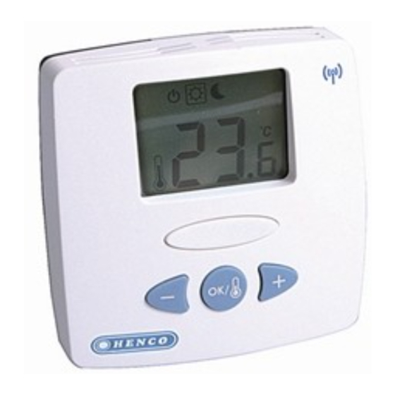
- Page 5 DISPLAY 1: Operating mode menu (active mode is framed). 2: Heating demand indication. 3: Cooling demand indication. 4: Batteries weak. 5: If lit- 6: Measured temperature or setting temperature. 7: °C or °F indicator. 8: Moving bars when transmitting a radio signal Or Title for installation Parameters (rF,...
-
Page 6: Mode Description
MODE DESCRIPTION Use the (OK) key to change the mode in the Operating mode menu. (The active mode is framed) OFF mode: Use this mode if the zone managed by the thermostat needs to be turned OFF. The display will be turned off and all parameters are saved. - Page 7 REDUCED operating mode: The comfort temperature will be followed all the time. By pressing (- or ( keys the comfort temperature starts to blink and can be adjusted. The measured temperature (OK) reappears after a few seconds.
-
Page 8: Technical Characteristics
TECHNICAL CHARACTERISTICS Measured temperature 0.1°C precision Operating temperature 0°C - 50°C Setting temperature 5°C 37°C by 0.5°C step range Proportional Integral Regulation regulation (PWM) (adjustable characteristics see installation menu) Electrical Protection Class II - IP30 Power Supply 2 x 3V (CR2430) Battery operated life ~ 2 years Radio frequency... - Page 9 INSTALLATION PARAMETERS MENU Press the (OK) key during 5 seconds, then use (- ) or ( +) to select the installation parameter to be adjusted. Press (OK) to toggle the parameter setting or edit the value. If the value starts to blink you can use (- ) or ( +) keys to adjust this value.
- Page 10 PARAMETERS Default value & other possibilities rF: Radio configuration mode (see the corresponding section). Press (OK) on this parameter to exit the parameters menu end come back to the main display. JO: Type of degrees displayed °C Celsius °F Fahrenheit J1: Operating mode: Hot for heating application CLd for cooling application...
- Page 11 Bp: Value of the proportional band in °C: 2.0 °C Adjustable 1°C to + 7°C Increase the value if the temperature in the room is unstable. J5: Anti-lock-braking function of the pump when on a particular day, start it up for one minute each day: Pmp Function activated Function deactivated J6: Selection of the sensor used for the regulation:...
- Page 12 J7: Selection of regulation type: rEg: Proportional band (PWM) hys: Static differential of 0.3°K Cp: Value of the compensation in °C: Adjustable 1°C to 8°C 2.0°C * This value must be adjusted by a specialist. A0: Calibration of the internal sensor (The calibration must be done after 12Hours working with the same setting temperature) - To check the temperature in the room, put a...
- Page 13 F0: Calibration of the external sensor. The calibration must be done same as described above if the external sensor is connected and used like an external ambiance sensor. If the external sensor is used as floor sensor, the thermometer should be put on the floor. FL: Lower limitation of the floor temperature.
- Page 14 - To assign (*) the RF thermostat with the UFH- ZONEHC-R or the UFH-ZONE-R you must put RF init (Please refer to the receiver leaflet for this). - After you have just pressed (OK) key during 5 sec, th The thermostat sends its configuration address by radio signal.
Need help?
Do you have a question about the UFH-THERM-RD and is the answer not in the manual?
Questions and answers